Article

Flying Sensor and Edge Network-Based Advanced Air Mobility Systems: Reliability Analysis and Applications for Urban Monitoring

by
Herman Fesenko
1,
Oleg Illiashenko
1,2,*,
Vyacheslav Kharchenko
1,
Ihor Kliushnikov
1,
Olga Morozova
1,
Anatoliy Sachenko
3,4 and
Stanislav Skorobohatko
1
1
Department of Computer Systems, Networks and Cybersecurity, National Aerospace University “KhAI”, 17, Chkalov Str., 61070 Kharkiv, Ukraine
2
Software Engineering & Dependable Computing Laboratory, Institute of Information Science and Technologies “Alessandro Faedo”—ISTI CNR, Area della Ricerca CNR di Pisa, Via G. Moruzzi 1, 56124 Pisa, Italy
3
Department of Informatics and Teleinformatics, Kazimierz Pulaski University of Technology and Humanities in Radom, ul. Malczewskiego 29, 26-600 Radom, Poland
4
Research Institute for Intelligent Computer Systems, West Ukrainian National University, 11, Lvivska Str., 46009 Ternopil, Ukraine
*
Author to whom correspondence should be addressed.
Drones 2023, 7(7), 409; https://doi.org/10.3390/drones7070409
Submission received: 10 May 2023 / Revised: 17 June 2023 / Accepted: 19 June 2023 / Published: 21 June 2023
(This article belongs to the Special Issue AAM Integration: Strategic Insights and Goals)

Abstract

:
Typical structures of monitoring systems (MSs) that are used in urban complex objects (UCOs) (such as large industrial facilities, power facilities, and others) during the post-accident period are combined with the technologies of flying sensor networks (FSNets) and flying edge networks (FENets) (FSNets and FENets); cloud/fog computing and artificial intelligence are also developed. An FSNets and FENets-based MS, composed of one of the Advanced Air Mobility (AAM) systems classes, which comprise main and virtual crisis centers, fleets of flying sensors, edge nodes, and a ground control station, is presented and discussed. Reliability and survivability models of the MS for the UCOs, considering various operation conditions and options of redundancy, are developed and explored. A tool to support the research on MS reliability, survivability, and the choice of parameters is developed and described. Crucially, this paper enhances the technique for assessing systems using the multi-parametrical deterioration of characteristics as a class of multi-state systems. Problems that may arise when using FSNets/FENet-based AAM systems are discussed. The main research results comprise a structural basis, a set of models, and a tool for calculating the reliability and survivability of FSNets/FENet-based AAM systems, with various options for distributing the processing and control resources between components, their failure rates, and degradation scenarios.

1. Introduction and Related Works

1.1. Motivation

Developing and implementing Advanced Air Mobility (AAM) systems is essential for contemporary mobile technology applications. The concept of AAM integrates various types of air mobility. Using sensor networks and edge computing technologies provides new opportunities for AAM systems. These technologies can be implemented as Flying Sensor Networks (FSNets) and Flying Edge Networks (FENets).
FSNets are networks of unmanned aerial vehicles (UAVs) equipped with various sensors for data acquisition and communication; these capabilities enable the networks to exchange information. FSNets have the potential to revolutionize multiple industries by providing a more efficient and cost-effective method for data collection and analysis.
FENets are UAV networks equipped with computing and communication capabilities. FENets have the potential to provide edge computing services in areas where traditional infrastructure is not available or may be limited. This can enable the introduction of new applications and services cost-effectively and reliably. FENets are a relatively new technology, and their evolution is ongoing; however, we can identify several stages of their evolution based on the current state of the technology and its expected development in the future:
  • First Generation FENets: The first generation of FENets was focused on developing the underlying technology for UAVs and edge computing. The primary focus was developing the necessary hardware and software to enable UAVs to provide edge computing services.
  • Second Generation FENets: The second generation of FENets was characterized by developing more advanced hardware and software to support more sophisticated edge computing services. These FENets were expected to be smaller, faster, and more reliable than first-generation FENets.
  • Third Generation FENets: The third generation of FENets is expected to be more autonomous and capable of performing complex tasks without human intervention. These FENets are expected to be equipped with advanced AI and machine learning capabilities, thus enabling them to adapt to changing conditions and make real-time decisions.
  • Fourth Generation FENets: The fourth generation of FENets is expected to be even more advanced, with the ability to operate in more challenging environments and perform more complex tasks. These FENets are expected to be equipped with advanced sensors, communication systems, and propulsion technologies, thus enabling them to operate in a broader range of environments.
Hence, the evolution of FENets is ongoing, and we can expect to see new technological developments and advancements. As technology evolves, we can expect FENets to become more capable, reliable, and widely used in various applications.
Using both FSNets and FENets as flying elements of monitoring systems (MSs) in urban complex objects (UCOs) (such as extensive industrial facilities, power facilities, etc.) during the post-accident period can provide several advantages:
  • Improved data collection: FSNets can collect real-time data from various sensors, whereas FENets can process and analyze this data at the edge of the network. This can enable more efficient and accurate decision-making.
  • Enhanced situational awareness: FSNets can provide real-time data on the environment, whereas FENets can process and analyze this data to provide actionable insights. This can improve situational awareness and enable faster responses to changing conditions.
  • Increased flexibility: The combination of FSNets and FENets can provide increased data collection, processing, and analysis flexibility. This can enable new applications and services to be developed cost-effectively and reliably.
  • Reduced latency: FENets can provide low-latency services. At the same time, FSNets can collect and transmit data in real-time, reduce the time it takes to respond to changing conditions and improve overall MS performance.
  • Improved reliability: The combination of FSNets and FENets can provide an increased level of reliability by distributing computing and communication capabilities across a fleet of UAVs. If one UAV fails, others in the network can take over its tasks, thus ensuring continuity of service.
It is also important to note that flying edge computing (FEC) solutions are often combined with solutions based on flying cloud and fog computing (FCC and FFC).
This makes it necessary to conduct research related to the following:
  • The classification and development of the typical structures of FSNets and FENets for MSs for use in UCOs; these tasks require a combination of mobile (flying) sensor network, edge and cloud computing, and artificial intelligence technologies. Such solutions can form a structural basis for developing and involving monitoring AAM systems.
  • The analysis of the reliability and survivability issues of these systems considers various operation conditions, a set of centers for crisis management, and the control of FSNets and FENets applications. An assessment of reliability and survivability indicators is a critical task in the context of meeting operation requirements.
  • The development of model-based recommendations for choosing structures and their parameters considers features of the monitoring tasks and UCOs. This is a vital task because many urban services and applications exist, and the choice of structure should be well-considered.

1.2. State of the Art

Using FSNets to monitor UCOs is becoming a more popular method. In particular, UAVs acting as flying sensors are used to perform the following tasks: air pollution (quality) monitoring [1,2,3,4]; gas sensing [5,6,7,8]; radiation monitoring and mapping [9,10,11,12,13]; the monitoring of dust particles produced by mining activities [14,15]; and the early detection of a threat following a chemical, biological, radiological, nuclear, and explosive event [16].
Sufficient attention is paid to architectural solutions based on FCC, FEC, and FFC. In [17], FCC, FEC, and FFC were treated as component technologies of the Internet of Flying Things (IoFT), also known as the Internet of drones (IoD). The IoFT (IoD) is a multi-layered architecture that comprises the advantages of Flying Ad hoc Networks (FANET) and the Internet of Things (IoT); it is designed to manage the flying network and provide rapid access to UAVs for controlling space, Internet resources, and cloud environments. Next, we will analyze the leading publications that discuss using FCC, FEC, and FFC in various contexts.
The authors of [18] propose a resource-oriented architecture designed to facilitate the modeling of resources and the services provided by UAVs. At the same time, UAVs are equipped with an Arduino board and onboard Wi-Fi equipment; they act as servers with cloud resources that can be accessed via application programming interfaces. In [19], the authors extend the capabilities of their prototype, presented in [18], by integrating an Arduino board with humidity and air temperature sensors, thus endowing the prototype with the ability to control these sensors through an interface using RESTful web services. The authors of [20] present a cloud architecture designed to ensure effective interactions between UAVs and wireless sensor networks. In this architecture, the UAV physical resource layer is separate from the control layer, comprising software, software-defined networks, and network function virtualization. In [21], a cloud-based platform for UAV control that allows users and the cloud platform to interact with the UAV simultaneously is considered. Users enter the necessary parameters, and the cloud platform, which has an Internet connection with the ground control station (GCS), takes over the control functions of the UAV by the user’s requirements. The authors of [22] propose a structure that allows users to access a UAV that acts as a commercial service provider using a cloud environment. The cloud coordinator monitors the optimal use of UAV resources and the provision of established security requirements in this structure. It provides a means of communication between users and UAVsmanages task allocation, and provides access to UAVs for users of different categories. In [23], a three-level cloud architecture is considered. Terrestrial wireless sensors represent the first level of the architecture; UAVs form the second level, and it comprises an onboard cloud platform that receives data from the sensors and sends them to the GCS; and the third level is the cloud control center, which is responsible for processing and analyzing the collected data for decision making. In [24], a cloud server capable of analyzing UAV flight data was implemented using Python; it also allows users to control and visualize UAV remotely. The authors of [25] propose a cloud system that helps to simultaneously control several UAVs, which can be used to collect and process data from ground sensors by utilizing a cloud environment. In [26], the possibility of using UAVs and ground servers to implement cloud computing while operating a scalable network that is responsible for collecting, processing, and delivering multimedia files to end users is considered. In [27], the authors present a primary and general conceptual model of the Cloud-SPHERE cloud platform. This platform can provide a secure communication channel between UAVs in the fleet and UAVs in the ground infrastructure as it implements mechanisms for identification, authentication, and data protection.
In [28], the features of FEC-based architecture are described; UAVs provide the necessary services to users in natural disaster areas with damaged ground communication infrastructure. This work also provides recommendations for optimizing the number and locations of UAVs for the more effective implementation of boundary computing; this is intended to work in the users’ interests. In [29], an architecture for a ground-air integrated mobile edge network called AG630 MEN is proposed; this network comprises UAVs as boundary network controllers, efficiently distributing computing and data storage resources. The authors of [30] demonstrate a framework’s capability to utilize ground vehicles and UAVs so that edge servers can be used to organize communication, perform necessary calculations, and ensure storage of the required information. The results of the experiments confirmed that the use of the developed framework provides high mobility, a high bandwidth, and low latency. To guarantee a high quality of service for resource-intensive and online applications, a hybrid model composed of cloud and edge computing processes for UAV swarms is proposed in [31]. This model expands upon the capacity of UAV resources by using edge servers capable of processing data with low latency. Moreover, this paper describes an algorithm for the interactions between edge and cloud computing processes that process and store large data in the cloud. The wireless mobile system presented in [32] uses UAVs to offload computing tasks solved by mobile ground users. In addition, it allows for minimal UAV energy consumption as the offloading of computations and constructing the UAV flight path are jointly optimized. The simulation results showed that the proposed system outperforms other reference schemes with regard to convergence. In [33], the same authors considered the possibility of using the system developed in [32] to maximize the speed of calculations by implementing two algorithms to optimize limit calculations for the UAV, its energy resources, and flight trajectory. The algorithm for offloading user tasks, which applies limit calculations to UAV servers and subsequently processes the results at specified access points, is presented in [34]. This algorithm also makes it possible to optimize the distribution of computing resources between the UAV and users. The algorithm also makes it possible to optimize bandwidth allocation and the UAV flight path. In [35], the possibility of using semi-Markov decision-making processes and deep learning technologies was explored; reinforcements were used to maximize the bandwidth of a UAV server that performed boundary computations in real-time for the benefit of ground users. In [36], the authors applied game theory methods to solve the problem of offloading calculations in flying wireless networks while simultaneously reducing UAV energy resource consumption and task delay. Per the proposed approach, UAVs, GCSs, and edge servers are considered players that interact with each other during the execution of computational tasks. The task is processed on the UAV, which is offloaded to the nearest GCS or edge server. In [37], problems related to the application of the multi-level architecture of the 5G network are discussed; it was found that UAVs act as flying nodes in edge computing. In [38], an iterative clustering algorithm with adequate coverage is proposed; the algorithm uses coordinate and block descent methods to maximize the coverage of UAV sensors which perform boundary calculations, subject to restrictions on the delay time. A digital twin framework for Internet of Things (IoT) networks, wherein UAVs act as flying mobile edge computing servers, and which support the task of offloading when flying, is proposed in [39]. The study [40] considers a new blockchain-enabled AI paradigm employing both wireless miners and edge computing at flying things for security requiring heterogeneous vehicle systems to enhance the security of federated learning (FL) implementation and develop a privacy-preserving model [41] suggests a novel method for enabling extensive AI task processing on UAVs for remote sensing applications. This method makes use of edge computing in UAVs. The proposed system design uses a cloud-edge hybrid approach, comprising cloud handling data storage, manipulation, visualization, and edge-handling AI tasks. The authors of [42] provide a well-designed AI and Multi-access Edge Computing-enabled architecture for a UAV-assisted future network. This architecture features a QoS-aware service provisioning capability and an effective deep reinforcement learning (DRL) algorithm for real-time and proactive trajectory planning and optimization.
The research presented in [43] addresses the problem of using FFC in Industry 4.0. This paper describes, in detail, the structure that UAVs use to implement FFC offloading tasks; ground sensors perform this task and optimize the distribution of such functions with the help of a greedy algorithm to maximize the number of tasks implemented within a certain period. The FFC system, UAVFog [44], uses fog computing and UAV mobility, and it allows for the storage of the required data, flexible communication, low latency for IoT applications, Internet of Things services, brokerage services, and services based on location. In [45], aspects of offloading tasks using UAVs in a hierarchical fog computing system are investigated. Multiple Input Multiple Output (MIMO) technologies were used to effectively interact with UAVs (where FFCs are implemented) and the terrestrial cloud environment (where basic calculations are performed and results from those calculations are stored). In [46], the authors propose an approach to integrate a fog computing system with a UAV swarm system to perform calculations on the UAV with low latency and a high level of reliability. In addition, the authors demonstrated the capabilities of the genetic heuristic algorithm they developed to optimize the allocation of tasks to reduce the energy resources of UAVs maximally. In [47], the features of FFC implementation in FANET are considered in detail, and services that such networks can provide based on FFC are described.
Thus, the main problematic issues that are raised in literary sources that are devoted to the application of FCC, FEC, and FFC are as follows:
  • scalability, reliability, stability, and security of the proposed architectures;
  • offloading tasks;
  • minimization of energy consumption;
  • allocation of resources;
  • communication and coverage organization;
  • delays during real-time operations;
  • features of management of UAVs, their interaction, trajectories, and route optimization;
  • information processing and storage in the cloud environment.
As a rule, the presented sources consider flying computing only in connection with the presence of UAVs as part of the proposed architectures. However, very often, these architectures enable the existence of components that are responsible for conducting similar ground computing processes (GCC, GEC, GFC). Such a combination of ground and flying computing processes makes most architectures more efficient.
It is also important to note that UAV-based monitoring systems for UCOs can be considered multi-state systems and should be assessed in relation to their reliability and survivability [48,49,50].

1.3. Objectives

This paper aims to present a structure comprising the FSNets and FENets-based monitoring system for urban complex objects to develop its reliability/survivability models.
The objectives of the paper are as follows:
  • to define the methodology of the investigation;
  • to classify and describe variants of the FSNets and FENets-based system structures;
  • to develop and describe the general scheme of the FSNets and FENets-based monitoring system;
  • to develop and explore reliability and survivability models for the monitoring system;
  • to develop a tool to support research on MS reliability, survivability, and the choice of parameters.
The rest of the paper is structured as follows. The next section is devoted to the methodology of the investigation, the classification, and the description of the variants of the FSNets and FENets-based system structures; tasks that can be performed using elements of the MS with various AI methods are also described in this section. Section 3 presents reliability and survivability models for the MS, and the results of this investigation are given. Section 4 describes a tool for calculating the reliability/survivability indicators of the MS. Section 5 discusses problems that may arise when using FSNets/FENet-based monitoring systems. Section 6 presents the main contributions of the study, briefly summarizes the results obtained, and highlights steps for further research.

2. The Methodology and Researched Structures

2.1. Methodology, Research Questions, and Stages

The investigation’s methodology includes a research hypothesis and the main research questions, principles, considered factors, and restrictions. The consequences of the research and applied mathematical apparatus are also detailed in this section.
Both flying edge networks and flying sensor networks can be used to support AAM. Flying edge networks can provide communication capabilities to air taxis and delivery drones, thus enabling them to operate safely and efficiently in urban environments. Flying sensor networks can monitor air traffic and detect potential hazards, thus improving safety and efficiency in air transportation systems.
The research hypothesis is that the FSNets and FENets-based AAM system, created to monitor and serve urban objects, is a complex multi-level one with dynamically changed parameters. These parameters describe a set of performed functions, including the structure of the sensor share, communications, centers of control and decision-making, reliability, and dependability-related attributes and characteristics.
Overall, the development of flying edge networks and flying sensor networks represents an exciting new frontier in air mobility, and these technologies are likely to play an increasingly important role in the future of transportation. Such systems can be reconfigurable, survivable, and resilient. These characteristics are significant when applying such systems for controlling and measuring the required parameters and collecting and processing information about UCOs in various (normal, pre-, and post-accident) conditions. These systems can undergo controlled reconfigurations and degradations to minimize losses and failure rates caused by failures of different structural components in conditions wherein fast-acting external influences in the physical and information environment occur.
The following research questions are formulated and considered:
Research Question RQ1: What are the options for FSNets structures given the possible distribution of measurement and information processing methods within the levels of the systems, centers of decision-making, and so on? Which structure can be chosen once as a reference to demonstrate various possibilities and properties?
Research Question RQ2: How should reliability models of the MS structure be developed and researched to assess the influence of the characteristics of various components on reliability indicators of the MS during the pre-accident period of the monitored UCO?
Research Question RQ3: How should the possible degradation of the MS be analyzed and considered? How should failures concerning sensors, communication, and decision-making centers during the post-accident period be considered and analyzed? Which recommendations can provide controlled degradation?
Research Question RQ4: Which reliability assessment and decision support tools can be offered for various issues?
The methodology of the investigation is based on the following:
  • a systematic analysis of classification attributes so that the MS can suggest a set of structures that consider various levels of the system, applied technologies of sensors, ground/flying fog, edge and cloud computing, and the distribution of processing resources (stage 1);
  • the development of the generalized MS structure for reliability and survivability research, considering component failures using the known techniques of reliability block diagrams (RBDs) and degradation diagrams (DDs) (stage 2);
  • the development of a tool to support the research on MS reliability and choice of parameters (stage 3).

2.2. Classification and Description of Variations in Structures with Flying/Ground Sensors and Cloud/Edge/Fog Computing

Considering the approaches of FCC, FEC, and FFC, noted in [51], let us consider the various variations between structures when FEC, FCC, and FFC are implemented.
A variation in the structure of FCC, as shown in Figure 1, can be applied to the decision support scenario during emergency response activities, when all end devices (ED) ED-1, ED-2, ... ED-m can exchange information with each other. Still, they cannot access the outside world. EDs can generally act as ground (stationary/mobile) and flying sensors. Local services (for example, offloading tasks) are provided at the level of ground edge computing (using ground edge nodes GEN-1, GEN-2, ... GEN-k) or at the level of ground fog edge computing (using ground fog computing nodes GFN- 1, GFN-2, ... GFN-r). Global services (for example, data collection, provision of security functions, application of computing resources, and support for decision-making) are provided by the UAV fleet comprising UAVs that act as flying cloud nodes (FCN) FCN-1, FCN-2, ... FCN-s. Such a fleet can be regarded as a subsystem of the flying cloud computing process (SubFCC).
The variation in the structure with FEC, as shown in Figure 2, wherein the fleet of UAVs act as a subsystem of the flying edge computing process (SubFEC), is located near the data sources (end devices ED-1, ED-2, ... ED-m); the variation provides the data sources with necessary services and carries out the required calculations on the flying edge nodes FEN-1, FEN-2, ... FEN-n. The proximity of these nodes to the data sources reduces the delay time, improves the bandwidth, and increases the network’s service life due to the more efficient use of the end devices’ battery resources. If the SubFEC cannot provide the necessary service, it can be supplied via ground cloud computing (GCC).
Regarding the variation in the structure with FFC, as shown in Figure 3, the UAV fleet comprises UAVs that act as flying fog nodes (FFN) FFN-1, FFN-2, ... FFN-p. Such a fleet can be regarded as a subsystem of the flying fog computing process (SubFFC). This structure allows for the combination of wireless channels, ground cloud servers, and end devices ED-1, ED-2, ... ED-m to ensure a higher storage capacity, calculation speed, and low latency for the end devices.
The MS consists of the following components:
  • A main crisis center (MCC) designed to provide solutions aimed at preventing and eliminating the consequences of accidents at the UCO, as well as forecasting the occurrence of such accidents and assessing their impact.
  • A virtual crisis center (VCC) that is formed by a group of external experts who remotely convene with the relevant staff of the MCC to provide solutions aimed at preventing and eliminating the consequences of accidents at the UCO.
  • A ground monitoring subsystem (SubGM) comprising EDs (sensors) responsible for measuring critical technological process parameters or parameters that characterize the degree of environmental pollution and the meteorological conditions.
  • A fleet of UAVs (FoU) that can perform one or a combination of the following functions: collect information from EDs (sensors), partially process this information, transmit it to the MCC.
  • A ground control station (GCS) that manages the FoU using external pilots (operators).
Considering the tasks performed by the components of the MS for UCO, the authors suggest using certain types of flying and ground edge/cloud/fog computing methods, as shown in Table 1.

2.3. Artificial Intelligence to Service the Monitoring System

The application of AI to network tasks has gained popularity over the past few decades. For example, AI is widely used in the network domain because it can interact with complex environments to intellectualize decision-making processes. AI methods can improve network performance in many subdomains, such as resource allocation, network traffic prediction and classification, congestion control, and routing. The elements of the MS, which form ground/flying networks and utilize FEC, FCC, and FFC to expand their capabilities, have to ensure a seamless connection, meet the quality of service requirements for many end devices, and process the significant amount of data created by the physical environment.
AI methods that offer robust analysis, learning, optimization, and intelligent recognition capabilities can be integrated into elements of the MS for intelligent performance optimization, the discovery of necessary monitoring information, advanced learning, structure organization, and complex decision support for predicting the consequences of accidents at the UCO and for responding to such accidents.
Based on the conducted analysis, a list of tasks was obtained; these tasks can be performed by elements of the MS using various AI methods (Table 2). The methods used were as follows [52]: deep learning (DL); deep supervised learning (DSL); deep reinforcement learning (DRL); fuzzy inference (FI); federated learning (FL); genetic algorithm (GA); reinforcement learning (RL); reinforcement learning based on ant colony optimization (RL-ACO).
The frequency with which specific AI methods are used by elements of the MS is shown in Table 3.
The table shows that RL is the most requested AI method, which was used 18 times in the described set of structures. The DL, DRL, and GA methods are also popular and were used 15 times. The least popular method is RL-ACO, which was only used three times and by three elements. These results can provide a starting point for analyzing AI methods applied to such a class of systems.

3. Reliability and Survivability Models

3.1. Stages of Assessment

The stages of assessment are as follows:
  • developing and describing a general scheme of the MS;
  • defining UAVs so that they can be used as an FSen/FEN;
  • developing an RBD for the MS;
  • developing and exploring the reliability and survivability models of the MS;
  • developing and describing a tool for calculating reliability/survivability indicators.

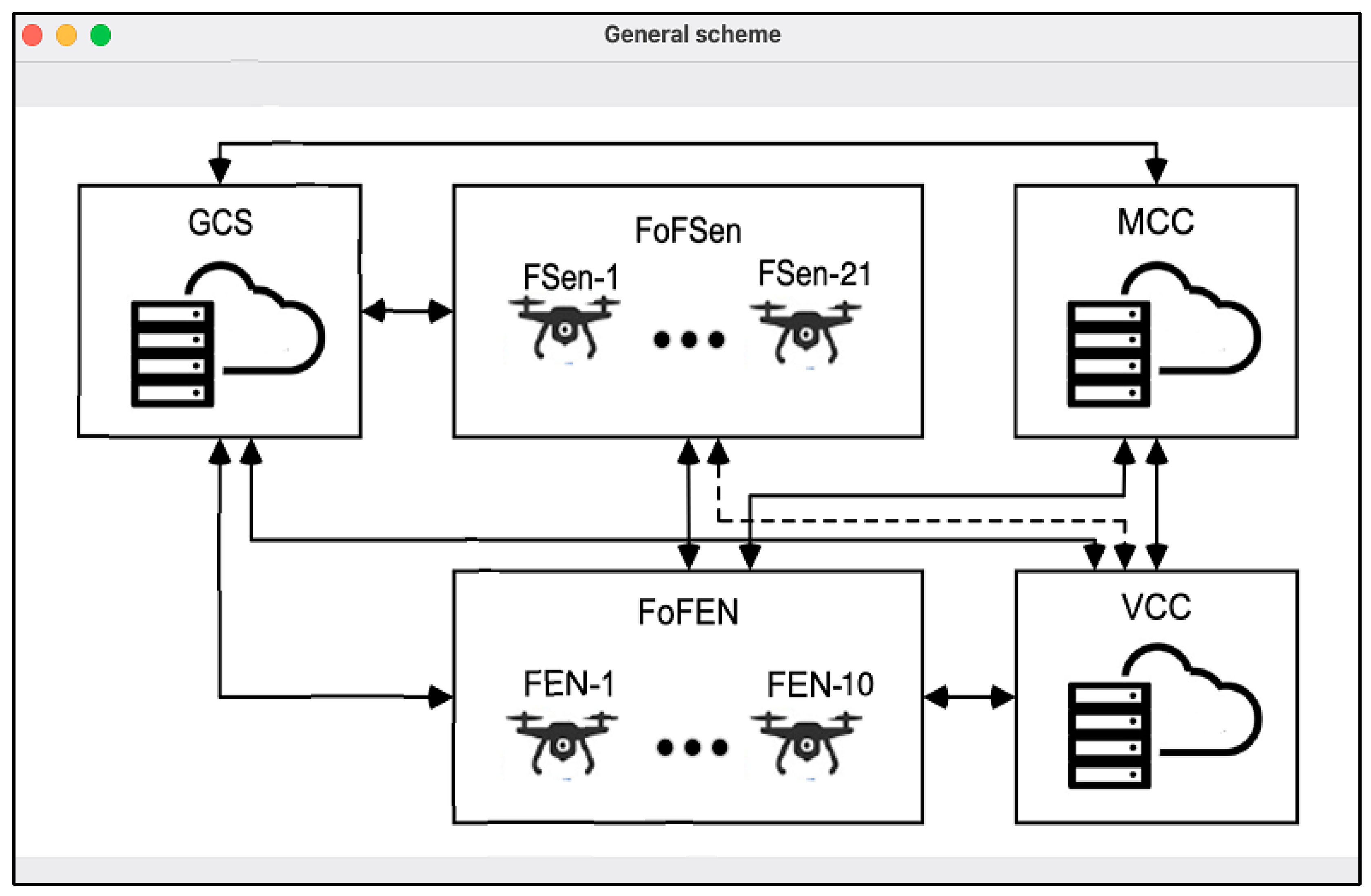
3.2. General Scheme of the Monitoring System

The analyzed MS is an adaptation of the MS presented in Section 2.2, and it comprises the following elements (Figure 4):
  • a fleet of flying sensors (FoFSen) that are deployed to measure the parameters characterizing the degree of environmental pollution and meteorological conditions (such sensors can be deployed instead of damaged stationary monitoring stations);
  • a ground control station (GCS), which manages the UAV using external pilots (operators);
  • a fleet of flying edge nodes (FoFEN) that are deployed to collect information from flying sensors, partially process this information, and transmit it to the main crisis center (MCC);
  • a main crisis center (MCC) that is designed to provide solutions aimed at preventing and eliminating the consequences of accidents at the UCO, as well as forecasting the occurrence of such accidents and assessing their impact;
  • a virtual crisis center (VCC) that is formed by a group of external experts who remotely convene with the relevant staff of the MCC to work out solutions to prevent and eliminate the consequences of accidents at the UCO.
The MS under consideration functions as follows.
In the event of an accident at the UCO, UAVs acting as flying sensors and UAVs operating as flying edge nodes travel to designated places to deploy a FoFSen and FoFEN, respectively. After deploying the fleets, data concerning parameters characterizing the degree of environmental pollution and meteorological conditions, measured via the FoFSen, are transmitted to the FoFEN and VCC. If required, the FoFEN partially processes the data (stores the results of some calculations) and sends it to the MCC. The VCC accumulates and stores the data in a secure private cloud of the Internet, to which a group of external experts has access. This group’s main task is to analyze the information, develop proposals for responding to the accident, and transmit them to the MCC.
The MCC staff are involved in decision-making processes to prevent and eliminate the consequences of accidents at the UCO.
The GCS operators are assigned tasks that concern the FoFSen and FoFEN by the senior staff of the MCC, and they manage the fleets by the instructions of the tasks.
The MS has the following special features:
  • the MCC allows for the possibility of partially taking over control of the UAV in case the GCS fails;
  • the MCC has enough authorized and qualified specialists to make decisions concerning responding to an accident in the event when information is received from the VCC.
Depending on the tasks to be completed, and restrictions concerning the time taken to be implemented, the UAVs presented in Table 4 and Table 5 can be used as an FSen/FEN.
The values of the parameters (Table 4 and Table 5), such as name, manufacturers, engine type, and quantitative parameters, were obtained based on the generalization of expert experience and the analysis of publications [11,12,48,50,53]. These parameters form various variants regarding UAV fleet composition, assessing reliability, analyzing degradation options, and so on.

3.3. Reliability Models

3.3.1. Development

The evaluation of the reliability indicators of MSs is performed at the system design stage. The relevance of the tasks concerning the calculation of the reliability of MSs is explained by the fact that they answer the question regarding the effectiveness of the implementation of the developed system. In our research, the reliability function was chosen as a reliability indicator.
The used notations are as follows:
P γ ( t ) is the reliability function of γ , where γ = MS, GCS, FoFSen, FoFEN, MCC, VCC;
t is the operating time;
λ δ is the failure rate of δ , where δ = GCS, FSen, FEN, MCC, VCC;
m is the number of flying sensors;
n is the number of flying edge nodes;
k is the number of the main flying edge nodes.
The assumptions used are as follows:
  • elements of the MS have exponential time to failure (TTF);
  • during the operating time, the MS is considered to be an unrecoverable system;
  • the FoFEN has a structure of type “k-out-of-n”. The FoFEN with such a structure consists of n flying edge nodes and remains in an operable state until ( n k + 1 ) flying edge nodes have failed, where ( n k ) is the number of redundant flying edge nodes.
Below is a reliability block diagram (RBD) for the MS presented in Figure 5 and an equation for calculating the MS reliability function.
P M S ( t ) = P G C S ( t ) P F o F s e n ( t ) P F o F E N ( t ) P M C C ( t ) P V C C ( t )
where P G C S ( t ) = e λ G C S t , P F o F S e n ( t ) = e λ F S e n t m ,
P F o F E N ( t ) = j = k n n j e λ F E N t j 1 e λ F E N t n j ,   P M C C ( t ) = e λ M C C t ,   P V C C ( t ) = e λ V C C t

3.3.2. Choice of Parameter Values

Input parameters for simulation were selected by considering the publications [11,12,48,50] wherein assessments for similar systems and components were performed. Next, simulations were performed for the corresponding functions, such as the probabilities of the system states (operable states, non-operable states, partially operable states, and others), depending on time and sets of values for failure rates, system configurations, etc.
Most of these parameters and their values are known when designing and deploying systems so that calculations can be performed like ordinary probability functions.
If the interval values of these parameters are known, then calculations should be performed following the rules of interval mathematics.

3.3.3. Simulation and Analysis

Using Equation (1), some dependencies were obtained (Figure 6, Figure 7 and Figure 8), where initial data are as follows: λ F E N = 0.001 1/h (for Figure 6 only), λ F S e n = 0.0001 1/h (for Figure 7 and Figure 8 only), λ G C S = 0.001 1/h, λ V C C = 0.001 1/h, λ M C C = 0.001 1/h, m = 21 flying sensors, n = 9 flying edge nodes (for Figure 6 and Figure 7 only), k = 7 main flying edge nodes.
The analysis of the dependencies obtained enabled the following conclusions to be made:
  • The increase in operating time t , from 0 to 12, led to a reduction in the values of the reliability functions P M S t ; the values were reduced by 1.05 (from 1 to 0.95358), 1.08 (from 1 to 0.92985), and 1.1 (from 1 to 0.90671), at times of λ F S e n = 0.0001 1/h, λ F S e n = 0.0002 1/h, and λ F S e n = 0.0003 1/h, respectively (Figure 6).
  • The increase in operating time t , from 0 to 12, led to a reduction in the values of the reliability functions P M S t : the values were reduced by 1.05 (from 1 to 0.95358), 1.05 (from 1 to 0.95069), and 1.1 (from 1 to 0.94158) at times of λ F E N = 0.001 1/h, λ F E N = 0.003 1/h, and λ F E N = 0.005 1/h, respectively (Figure 7).
  • The utilization of more reliable (with a lower failure rate) FSen/FEN for the MS makes it possible to increase its reliability. For example, at t = 12   h , the reduction in the failure rate λ F S e n , from 0.0003 to 0.0001 , led to an increase in the reliability functions P M S t ; the functions increased by 1.05 (from 0.90671 to 0.95358) (Figure 6). As for FEN, at t = 12   h , the reduction in the failure rate λ F E N , from 0.005 to 0.001 , led to an increase in the reliability functions P M S t ; the functions increased by 1.01 (from 0.94158 to 0.95358) (Figure 7).
  • The increased number of redundant flying edge nodes also improved MS reliability. For example, at λ F E N = 0.005 1/h, this increase led to an increase in reliability functions P M S t ; the functions increased by 1.05 (from 0.92124 to 0.96446). It is important to note that the most significant effect was achieved by increasing the number of redundant flying edge nodes from 1 to 2 (Figure 8).

3.4. Models of the MS as Multi-State Systems

3.4.1. Development

The operation of the MS during the post-accident mode can be characterized by many adverse factors affecting its performance. In this case, it is advisable to discuss MS survivability in terms of how it can be measured using the probability of the total performance of the MS at a given level. In other words, the MS can be considered a multi-state system (MSS). Such a system can degrade from a fully operable state (Level 0) to a non-operable state by traversing through some partially operable states (Levels 1, 2, …, f).
The degradation of the MS is possible due to the implementation of the following mechanisms:
  • in the event of a VCC/GCS failure, its functions can be partially performed by the MCC;
  • the failure of FoFSen/FoFEN occurs only after the failure of more than one α FSen/ ω FEN.
The degradation levels of the MS and its failed corresponding elements are depicted in Figure 9.
The notations used are as follows:
  • α is the number of non-operable flying sensors needed for the FoFSen to transition from a fully operable state to a partially operable state;
  • β is the number of main non-operable flying edge nodes needed for the FoFEN to transition from a fully operable state to a partially operable state;
  • ω is the number of non-operable flying edge nodes required for the fleet of the flying edge nodes to transition from a fully operable state to a partially operable state, where ω = n k + β ;
  • G C S ¯ is the GCS in the non-operable state;
  • V C C ¯ is the VCC in the non-operable state;
  • α F S e n ¯   α flying sensors represent the non-operable state (FoFSen is in a partially operable state FoFSen_L1);
  • ω F E N ¯   ω flying edge nodes represent the non-operable state (FoFSen is in a partially operable state FoFEN_L1);
  • P M S _ 0 is the probability of the MS being in a fully operable state, where P M S _ 0 = P M S ;
  • P M S _ i j i is the probability of the MS being in a partially operable state i j i , where i is the degradation level number and j i is the state number at Level i .
The probabilities concerning whether the MS is in a partially operable state can be calculated using Equations (2)–(15).
P M S _ 11 ( t ) = 1 P G C S ( t ) P F o F s e n ( t ) P F o F E N ( t ) P M C C ( t ) P V C C ( t )
P M S _ 12 ( t ) = P G C S ( t ) P F o F s e n _ L 1 ( t ) P F o F E N ( t ) P M C C ( t ) P V C C ( t )
where P F o F s e n _ L 1 ( t ) = 1 e λ F S e n t α e λ F S e n t ( t ) m α .
P M S _ 13 ( t ) = P G C S ( t ) P F o F s e n ( t ) P F o F E N _ L 1 ( t ) P M C C ( t ) P V C C ( t )
where P F o F E N _ L 1 ( t ) = 1 e λ F E N t n k + β e λ F E N t k β
P M S _ 21 ( t ) = 1 P G C S ( t ) P F o F s e n _ L 1 ( t ) P F o F E N ( t ) P M C C ( t ) P V C C ( t )
P M S _ 22 ( t ) = 1 P G C S ( t ) P F o F s e n ( t ) P F o F E N _ L 1 ( t ) P M C C ( t ) P V C C ( t )
P M S _ 23 ( t ) = 1 P G C S ( t ) P F o F s e n ( t ) P F o F E N ( t ) P M C C ( t ) 1 P V C C ( t )
P M S _ 24 ( t ) = P G C S ( t ) P F o F s e n _ L 1 ( t ) P F o F E N _ L 1 ( t ) P M C C ( t ) P V C C ( t )
P M S _ 25 ( t ) = 1 P G C S ( t ) P F o F s e n _ L 1 ( t ) P F o F E N ( t ) P M C C ( t ) 1 P V C C ( t )
P M S _ 26 ( t ) = P G C S ( t ) P F o F s e n ( t ) P F o F E N _ L 1 ( t ) P M C C ( t ) 1 P V C C ( t )
P M S _ 31 ( t ) = 1 P G C S ( t ) P F o F s e n _ L 1 ( t ) P F o F E N _ L 1 ( t ) P M C C ( t ) P V C C ( t )
P M S _ 32 ( t ) = 1 P G C S ( t ) P F o F s e n _ L 1 ( t ) P F o F E N ( t ) P M C C ( t ) 1 P V C C ( t )
P M S _ 33 ( t ) = 1 P G C S ( t ) P F o F s e n ( t ) P F o F E N _ L 1 ( t ) P M C C ( t ) 1 P V C C ( t )
P M S _ 34 ( t ) = P G C S ( t ) P F o F s e n _ L 1 ( t ) P F o F E N _ L 1 ( t ) P M C C ( t ) 1 P V C C ( t )
P M S _ 41 ( t ) = 1 P G C S ( t ) P F o F s e n _ L 1 ( t ) P F o F E N _ L 1 ( t ) P M C C ( t ) 1 P V C C ( t )

3.4.2. Simulation and Analysis
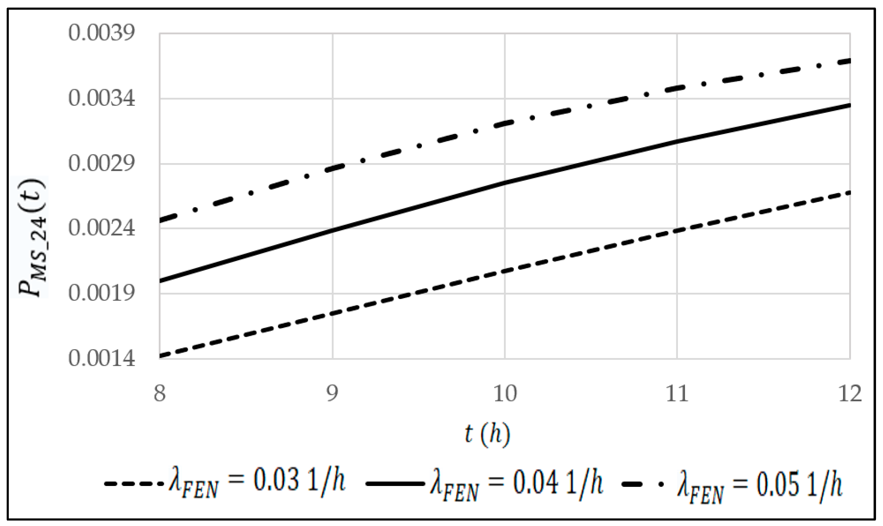
For a more detailed discussion, we have chosen partially operable state 24. The interest in this state is explained by the fact that it is characterized by the partial failures of two flying elements of the monitoring system at once—FoFSen and FoFEN.
Using Equation (8), some dependencies were obtained (Figure 10 and Figure 11), and the initial data are as follows: λ F E N = 0.03 1/h (for Figure 11 only), λ F S e n = 0.01 1/h, λ G C S = 0.0025 1/h, λ V C C = 0.007 5 1/h, λ M C C = 0.0085 1/h, m = 6 flying sensors (for Figure 10 only), n = 4 flying edge nodes, k = 3 flying edge nodes, α = 1 flying sensors, β = 1 flying edge nodes.
The analysis of the dependencies obtained enables the following conclusions to be made:
  • The increase in the operating time t , from 8 to 12, led to an increase in the probability of the MS being in partially operable state 12  P M S 12 t ; the probability increased by 1.88 (from 0.00142 to 0.00268), 1.68 (from 0.00199 to 0.00335), and 1.5 (from 0.00247 to 0.00369), at times of λ F E N = 0.03 1/h, λ F E N = 0.04 1/h, and λ F E N = 0.05 1/h, respectively (Figure 10).
  • The increase in the operating time t , from 0 to 12, led to an increase in the probability of the MS being in partially operable state 12  P M S _ 12 ( t ) ; the probability increased by 1.96 (from 0.00154 to 0.00302), 1.88 (from 0.00142 to 0.00268), and 1.81 (from 0.00131 to 0.00238), at times of m = 5 , m = 6 , and m = 7 , respectively (Figure 11).
  • The utilization of more reliable (with a lower failure rate) FEN for the MS makes it possible to reduce the probability of the MS being in partially operable state 12  P M S _ 12 ( t ) . For example, at t = 12   h , the reduction in the failure rate λ F E N , from 0.05 to 0.03 , led to a reduction in the probability of the MS being in partially operable state 12  P M S 12 t ; the probability decreased by 1.38 (from 0.00268 to 0.00369) (Figure 10).
  • An increase in the number of flying sensors also decreases the probability of the MS being in partially operable state 12  P M S _ 12 ( t ) . For example, at t = 12   h , this increase led to a reduced probability of the MS being in partially operable state 12  P M S 12 t ; the probability decreased by 1.27 (from 0.00302 to 0.00238) (Figure 11).
The validation of the obtained results and the models occurred during the review and analysis of the physical nature of the quantitative values. Additionally, a sensitivity analysis of the dependency of MS reliability indicators on input parameters can be performed; however, these results were predicted using the functions described by Formulas (1)–(15). The following section will discuss these results using an example of the model’s application.

4. Case study

4.1. Tool for Calculating Reliability/Survivability Indicators

To automate the processes of calculating the reliability/survivability indicators that characterize the monitoring system under consideration and to generate the necessary diagrams, the authors developed a tool called “Calculation of the main indicators of the reliability and survivability of the monitoring system”.
This tool calculates the reliability and survivability indicators of the variations in MS structures, and it illustrates the initial, intermediate, and final results of the analysis.
This version does not solve search and optimization tasks but supports decision-making processes based on calculations.
The panel for entering the initial data and producing results is shown in Figure 12.
This panel allows the following initial data to be entered:
  • the total number of flying sensors;
  • the total number of flying edge nodes;
  • the total number of main flying edge nodes;
  • the failure rate of the ground control station (1/h);
  • the failure rate of a flying sensor (1/h);
  • the failure rate of a flying edge node (1/h);
  • the failure rate of the main crisis center;
  • the failure rate of the virtual crisis center;
  • the number of non-operable flying sensors needed for the fleet of flying sensors to transition from a fully operable state to a partially operable state;
  • the number of main non-operable flying edge nodes needed for the fleet of flying edge nodes to transition from a fully operable state to a partially operable state;
  • the number of non-operable flying edge nodes needed for the fleet of flying edge nodes to transition from a fully operable state to a partially operable state;
  • the operating time (h).
After entering the data, the result of the calculation of the MS reliability function is immediately displayed on the panel (“The reliability function of the monitoring system” cell, Figure).
In addition, the panel is equipped with the following buttons (Figure 12):
  • Show the general scheme of the monitoring system” button. After clicking this button, the user can see a window containing the general scheme of the MS.
  • Show the reliability block diagram of the monitoring system” button. After clicking on this button, the user can see a window containing the reliability block diagram of the MS.
  • Show the degradation levels of the monitoring system and failed elements that correspond to them” button. After clicking on this button, the user can see a window containing the degradation levels of the MS, the failed elements that correspond with them, and the probability of the MS being in a partially operable state i j i , where i is the degradation level number and j i is the state number at Level i .

4.2. Example of the Developed Tool Being Utilized

An example where the developed tool is utilized to determine reliability/survivability indicators and to generate the necessary schemes and diagrams using the following initial data, is as follows:
  • the total number of flying sensors = 21;
  • the total number of flying edge nodes = 10;
  • the total number of main flying edge nodes = 7;
  • the failure rate of the ground control station = 0.00025 1/h;
  • the failure rate of a flying sensor = 0.001 1/h;
  • the failure rate of a flying edge node = 0.005 1/h;
  • the failure rate of the main crisis center = 0.00085 1/h;
  • the failure rate of the virtual crisis center = 0.00075 1/h;
  • the number of non-operable flying sensors needed for the fleet of flying sensors to transition from a fully operable state to a partially operable state = 1 1/h;
  • the number of the main non-operable flying edge nodes needed for the fleet of flying edge nodes to transition from a fully operable state to a partially operable state = 1 1/h;
  • the number of non-operable flying edge nodes needed for the fleet of the flying edge nodes to transition from a fully operable state to a partially operable state = 4;
  • the operating time = 9 h;
  • the panel after entering the initial data is shown in Figure 13.
The result from calculating the MS reliability function is immediately displayed on the panel (Figure 13).
By clicking on the “Show the general scheme of the monitoring system” button, we can obtain the general scheme of the MS for the initial data used, as shown in Figure 14.
By clicking on the “Show the reliability block diagram of the monitoring system” button, we can obtain the reliability block diagram of the MS, as shown in Figure 15.
By clicking on the 
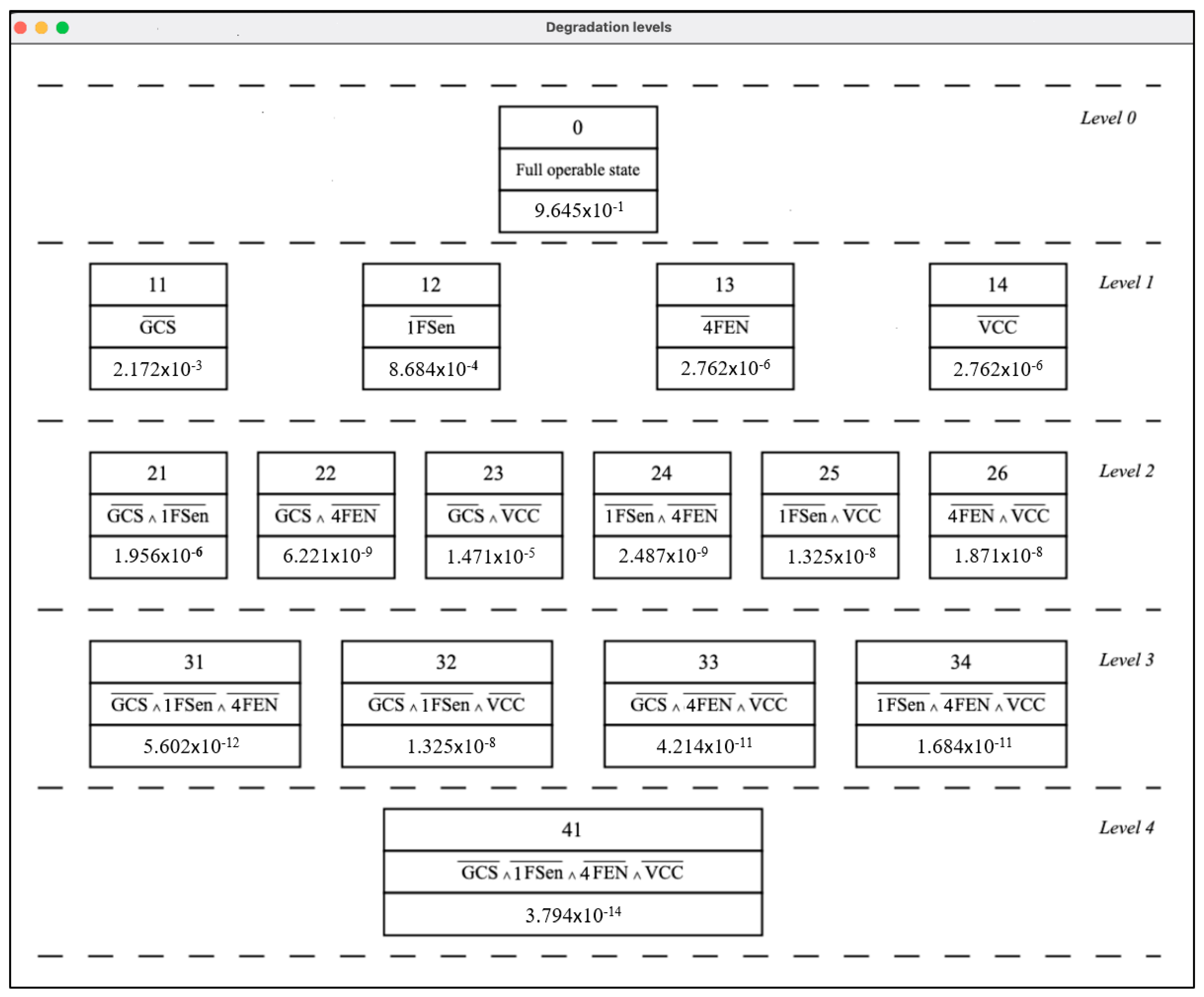
“Show the degradation levels of the monitoring system and failed elements that correspond to them” button, we can obtain the degradation levels of the MS, the failed elements that correspond with them, and the probability of the MS being in a partially operable state i j i , where i = 0, …, 4 is the degradation level number and j i is the state number at Level i , as shown in Figure 16.
Thus, Figure 14, Figure 15 and Figure 16 illustrate the functioning of the tool, which provides a presentation of the variations in system structures, their models in the form of reliability block diagrams, degradation schemes, and the results from the calculations of the probabilities of being in different states. The analysis of the actual results of the illustrative calculation (Figure 16) confirms the general conclusions of the model’s study, as presented in Section 3.

5. Discussion

Despite the new opportunities for monitoring complex objects by deploying FSNets and FENets, several problems may arise when using FSNets/FENet-based AAM systems for monitoring and serving urban objects.
Power Consumption. In the MS, most FSen and FEN are powered by batteries and can only remain operational for a limited period. Therefore, practical protocols and energy consumption mechanisms are essential for FSen/FEN to ensure a long service life for the flying parts of the MS. This requires improving the hardware and software of FSen/FEN components by integrating energy harvesting solutions or efficient routing protocols. For example, AI methods can be applied to predict the FSen/FEN residual energy level and dissipate it by fine-tuning transmission parameters and managing bandwidth. Extending the FSen/FEN flight time can be ensured using mobile and stationary automatic battery replacement/charging stations on FSen/FEN routes.
Interference. Communication channels GCS-FEN/FSen, FSen-FEN, FEN-MCC, and FEN-FCC may be broken due to interference, thus resulting in increased latency, which may also affect the overall MS network. Therefore, solving the interference problem becomes especially important in urban and industrial environments, wherein the number of interconnected devices on the same frequency range is significant. AI-based solutions can be applied in the MS to predict the signal-to-noise ratio based on the collected channel state information.
Mobility and route planning. FSen and FEN are often required to maneuver automatically without the remote intervention of an external pilot (operator) in random dynamic IoT applications. Therefore, many intelligent methods should be considered to enable autonomous FSen/FEN flights; this includes collision avoidance. AI algorithms are the most viable solutions which can be used to detect obstacles and avoid collisions.
Scalability. Scalability concerns relate to resources, applications, load balancing, and connections. For example, some mobile applications implemented on FEN require high levels of data to be inputted to successfully provide services, despite the heterogeneity of mobile devices and the dynamic behavior of application demands. The flying part of the MS must have an acceptable degree of scalability regarding the number of servers and required services. In places with adverse environmental conditions, it is difficult to establish a reliable connection and ensure reliable communication between mobile devices and servers.
Security. The control of, and interactions between FSen and FEN, with GCS, MCC, and VSS, are carried out using various wireless technologies (Wi-Fi, etc.), which are open to many security threats. It is necessary to propose and develop mechanisms that increase the security level of the flying part of the MS. Efforts should be focused on the physical aspects of the MS, its application, and control layers. Combining FSen/FEN with blockchain and AI is currently a cutting-edge area of research that could predict various attacks and malware.

6. Conclusions

The main contribution of this work is the development of FSNets/FENets structures that are embedded into AAM systems for monitoring and serving UCOs; reliability models for systems with uni- and multilevel degradation caused by failures of sensors and edge computing flying components; and management centers. A vital research result from this work concerns the enhancement of the technique for assessing systems with multi-parametrical deterioration of characteristics; these systems comprise a class of multi-state systems.
The results confirm the research hypothesis that the FSNets and FENets-based AAM system created to monitor and serve urban objects is a complex multilevel system with dynamically changing parameters.
The development of various variations within the MS structures, using UAVs acting as flying cloud/edge/fog computing subsystems, made it possible to form a set of base solutions that adhere to the level of ground cloud/edge computing, the level of flying cloud/edge/fog computing, and the level of flying/ground end devices; this may be subjected to further research and selection, depending on the assigned tasks.
The analyzed variant of the FSNets/FENet-based monitoring system for the urban complex object comprised the following: a fleet of flying sensors, a ground control station, a fleet of flying edge nodes, a main crisis center, and a virtual crisis center. The development and evaluation of the structure of such a system, using the proposed analytical models, made it possible to calculate reliability and survivability indicators and apply them to form recommendations for the selection of parameters, namely:
  • number of FSen/FEN;
  • redundancy scheme for FSen/FEN;
  • number of redundant FSen/FEN;
  • failure rate of FSen/FEN.
The analysis of variants using various AI methods makes it possible to determine which should be used to implement various functions. To provide more detailed recommendations, developing the proposed reliability models considering the reliability indicators of AI components is necessary.
Reliability (two-state) and survivability (multi-state) models that were developed for the MS allow:
  • the reliability block diagrams for the MS, depending on the features of the FoFSen and FoFEN structures, to be obtained;
  • the reliability function of the MS and its elements to be calculated;
  • the degradation levels, partially operable states, and failed elements that correspond to the levels to be defined;
  • the probability of the MS being in partially operable states to be calculated.
Using the developed modes, possibilities for improving MS reliability were assessed using more reliable flying sensors/edge nodes and introducing additional redundant flying sensors/edge nodes into FoFEN.
To automate the processes of calculating reliability/survivability indicators that characterize the monitoring system under consideration and which generate the necessary diagrams, the authors developed a tool called “Calculation of the main indicators of the reliability and survivability of the monitoring system”. The tool tests the mathematical models by checking the correctness of the calculation results. Reliability/survivability indicators provide a standardized framework to assess and compare different FSNets/FENet-based monitoring systems, thus enabling stakeholders to make informed decisions about their use in urban settings.
Thus, the key research results comprise a structural basis, a set of models, and a tool for calculating the reliability and survivability of FSNets/FENet-based AAM systems using various options to process and control resource distribution between components, their failure rates, and degradation scenarios.
It was noted that the following problems might arise when using FSNets/FENet-based monitoring systems: power consumption, interference, mobility and route planning, scalability, and security. Solving these problems can be addressed in future research. An exciting and essential topic is the development of digital twins and AI support for decision-making processes during the operation of FSNets/FENets in conditions wherein cyberattacks and other violations occur [54,55]. Another topic concerns identifying threats to wireless networks when attacks come from a UAV [56]. Additionally, models of MSs as smart systems that consider cyber security issues [57] could be developed to assess the availability and research influence of physical and information-based environments.
In urban settings, the successful implementation of digital twins and AI in FSNets/FENets requires a robust infrastructure, reliable communication systems, and careful consideration of ethical and privacy concerns. Moreover, the concept of FSNets/FENets-based AAM systems needs more detailed research, which considers the specifics of the urban services and various conditions in cities in potentially dangerous areas [58,59,60].

Author Contributions

Conceptualization, V.K. and H.F.; methodology, V.K. and I.K.; software, S.S.; validation, O.I. and A.S.; formal analysis, O.I.; investigation, O.I. and I.K.; resources, O.M.; data curation, H.F. and I.K.; writing—original draft preparation, H.F., S.S. and O.M.; writing—review and editing, O.I., H.F. and A.S.; visualization, S.S.; supervision, V.K.; project administration, A.S. All authors have read and agreed to the published version of the manuscript.

Funding

This research was funded by the Ministry of Education and Science of Ukraine, state grant registration number 0121U112172, project title “Scientific basis and methods of ensuring the dependability of UAV fleets of intelligent monitoring systems for potentially dangerous and military objects”. This publication reflects the views of the authors only, and the Ministry of Education and Science of Ukraine cannot be held responsible for any use of the information contained therein.

Informed Consent Statement

Informed consent was obtained from all subjects involved in the study.

Data Availability Statement

Data sharing is not applicable.

Acknowledgments

The authors appreciate the scientific staff of the Department of Computer Systems, Networks and Cybersecurity of the National Aerospace University “KhAI” for invaluable inspiration, hard work, and creative analysis during the preparation of this paper.

Conflicts of Interest

The authors declare no conflict of interest.

Abbreviations and Acronyms

The following abbreviations and acronyms included in the text are reported alphabetically.
Abbreviation/AcronymMeaning
AAMAdvanced Air Mobility
AI artificial intelligence
DDdegradation diagram
DLdeep learning
DRLdeep reinforcement learning
DSLdeep supervised learning
EDend device
FANETFlying Ad hoc Network
FCCflying cloud computing
FCNflying cloud node
FECflying edge computing
FENFlying edge node
FENetFlying Edge Network
FFCflying fog computing
FFNflying fog nodes
FIfuzzy inference
FLfederated learning
FoFENfleet of flying edge nodes
FoFSenfleet of flying sensors
FoUfleet of UAVs
FSenflying sensor
FSNetFlying Sensor Network
GAgenetic algorithm
GCCground cloud computing
GCSground control station
GECground edge computing
GENground edge node
GFCground fog computing
GFNground fog node
IoDInternet of drones
IoFTInternet of Flying Things
IoTInternet of Things
MCCmain crisis center
MIMOMultiple Input Multiple Output
MSmonitoring system
RBDreliability block diagram
RLreinforcement learning
RL-ACOreinforcement learning based on ant colony optimization
RQResearch Question
SubFCCsubsystem of flying cloud computing
SubFECsubsystem of flying edge computing
SubFFCsubsystem of flying fog computing
SubGMground monitoring subsystem
TTFtime to failure
UAVunmanned aerial vehicle
UCOurban complex object
VCCvirtual crisis center

References

  1. Evangelatos, O.; Rolim, J.D.P. AIRWISE—An airborneWireless Sensor Network for ambient air pollution monitoring. In Proceedings of the 4th International Conference on Sensor Networks (SENSORNETS), Angers, France, 11–13 February 2015; pp. 231–239. [Google Scholar]
  2. Villa, T.F.; Gonzalez, F.; Miljievic, B.; Ristovski, Z.D.; Morawska, L. An Overview of Small Unmanned Aerial Vehicles for Air Quality Measurements: Present Applications and Future Prospectives. Sensors 2016, 16, 1072. [Google Scholar] [CrossRef] [PubMed] [Green Version]
  3. Zulkifli, S.A.; Shukor, M.H.F.M.; Razman, F.N.; Wahab, M.H.A.; Idrus, S.Z.S. Air Drone Pollution Monitoring System with Self Power Generation. J. Phys Conf. Ser. 2020, 1529, 022103. [Google Scholar] [CrossRef]
  4. Jońca, J.; Pawnuk, M.; Bezyk, Y.; Arsen, A.; Sówka, I. Drone-Assisted Monitoring of Atmospheric Pollution—A Comprehensive Review. Sustainability 2022, 14, 11516. [Google Scholar] [CrossRef]
  5. Rossi, M.; Brunelli, D. Gas Sensing on Unmanned Vehicles: Challenges and Opportunities. In Proceedings of the 2017 New Generation of CAS (NGCAS), Genova, Italy, 6–9 September 2017; pp. 117–120. [Google Scholar]
  6. Tosato, P.; Facinelli, D.; Prada, M.; Gemma, L.; Rossi, M.; Brunelli, D. An Autonomous Swarm of Drones for Industrial Gas Sensing Applications. In Proceedings of the 2019 IEEE 20th International Symposium on “A World of Wireless, Mobile and Multimedia Networks” (WoWMoM), Washington, DC, USA, 10–12 June 2019; pp. 1–6. [Google Scholar] [CrossRef]
  7. Szczurek, A.; Gonstał, D.; Maciejewska, M. The Gas Sensing Drone with the Lowered and Lifted Measurement Platform. Sensors 2023, 23, 1253. [Google Scholar] [CrossRef]
  8. Iwaszenko, S.; Kalisz, P.; Słota, M.; Rudzki, A. Detection of Natural Gas Leakages Using a Laser-Based Methane Sensor and UAV. Remote Sens. 2021, 13, 510. [Google Scholar] [CrossRef]
  9. MacFarlane, J.W.; Payton, O.D.; Keatley, A.C.; Scott, G.P.T.; Pullin, H.; Crane, R.A.; Smilion, M.; Popescu, I.; Curlea, V.; Scott, T.B. Lightweight aerial vehicles for monitoring, assessment and mapping of radiation anomalies. J. Environ. Radioact. 2014, 136, 127–130. [Google Scholar] [CrossRef]
  10. Connor, D.; Martin, P.G.; Scott, T.B. Airborne radiation mapping: Overview and application of current and future aerial systems. Int. J. Remote Sens. 2016, 37, 5953–5987. [Google Scholar] [CrossRef] [Green Version]
  11. Kliushnikov, I.M.; Fesenko, H.V.; Kharchenko, V.S. Using automated battery replacement stations for the persistent operation of UAV-enabled wireless networks during NPP post-accident monitoring. Radioelectron. Comput. Syst. 2019, 4, 30–38. [Google Scholar] [CrossRef]
  12. Fesenko, H.; Kliushnikov, I.; Kharchenko, V.; Rudakov, S.; Odarushchenko, E. Routing an unmanned aerial vehicle during NPP monitoring in the presence of an automatic battery replacement aerial system. In Proceedings of the 2020 IEEE 11th International Conference on Dependable Systems, Services and Technologies (DESSERT), Kyiv, Ukraine, 24–27 May 2020; pp. 34–39. [Google Scholar]
  13. Chierici, A.; Malizia, A.; Di Giovanni, D.; Ciolini, R.; d’Errico, F. A High-Performance Gamma Spectrometer for Unmanned Systems Based on Off-the-Shelf Components. Sensors 2022, 22, 1078. [Google Scholar] [CrossRef]
  14. Alvarado, M.; Gonzalez, F.; Fletcher, A.; Doshi, A. Towards the Development of a Low Cost Airborne Sensing System to Monitor Dust Particles after Blasting at Open-Pit Mine Sites. Sensors 2015, 15, 19667–19687. [Google Scholar] [CrossRef] [Green Version]
  15. Alvarado, M.; Gonzalez, F.; Erskine, P.; Cliff, D.; Heuff, D. A Methodology to Monitor Airborne PM10 Dust Particles Using a Small Unmanned Aerial Vehicle. Sensors 2017, 17, 343. [Google Scholar] [CrossRef] [PubMed]
  16. Marturano, F.; Martellucci, L.; Chierici, A.; Malizia, A.; Giovanni, D.D.; d’Errico, F.; Gaudio, P.; Ciparisse, J.-F. Numerical Fluid Dynamics Simulation for Drones’ Chemical Detection. Drones 2021, 5, 69. [Google Scholar] [CrossRef]
  17. Zaidi, S.; Atiquzzaman, M.; Calafate, T. Internet of flying things (IoFT): A survey. Comput. Commun. 2020, 165, 53–74. [Google Scholar] [CrossRef]
  18. Mahmoud, S.; Mohamed, N. Broker architecture for collaborative UAVs cloud computing. In Proceedings of the International Conference on Collaboration Technologies and Systems (CTS’2015), Atlanta, GA, USA, 1–5 June 2015; pp. 212–219. [Google Scholar] [CrossRef]
  19. Mahmoud, S.; Mohamed, N.; Al-Jaroodi, J. Integrating UAVs into the Cloud Using the Concept of the Web of Things. J. Robot. 2015, 2015, 631420. [Google Scholar] [CrossRef] [Green Version]
  20. Sara, M.; Jawhar, I.; Nader, M. A softwarization architecture for UAVs and WSNs as Part of the cloud environment. In Proceedings of the International Conference on Cloud Engineering Workshops (IC2EW’2016), Berlin, Germany, 4–8 April 2016; pp. 13–18. [Google Scholar] [CrossRef]
  21. Majumder, S.; Prasad, M.S. Cloud based control for unmanned aerial vehicles. In Proceedings of the 3rd International Conference on Signal Processing and Integrated Networks (SPIN’2016), Noida, India, 11–12 February 2016; pp. 421–424. [Google Scholar] [CrossRef]
  22. Yapp, J.; Seker, R.; Babiceanu, R. UAV as a service: Enabling on-demand access and on-the-fly re-tasking of multi-tenant UAVs using cloud services. In Proceedings of the IEEE/AIAA 35th Digital Avionics Systems Conference (DASC’2016), Sacramento, CA, USA, 25–29 September 2016; pp. 1–8. [Google Scholar] [CrossRef]
  23. Youssef, S.B.H.; Rekhis, S.; Boudriga, N.; Bagula, A. A cloud of UAVs for the delivery of a sink as a service to terrestrial WSNs. In Proceedings of the 14th International Conference on Advances in Mobile Computing and Multi Media (MoMM’16), Singapore, 28–30 November 2016; pp. 317–326. [Google Scholar] [CrossRef]
  24. Zhang, Y.; Yuan, Z. Cloud-based UAV data delivery over 4G network. In Proceedings of the 10th International Conference on Mobile Computing and Ubiquitous Network (ICMU’2017), Toyama, Japan, 3–5 October 2017; pp. 1–2. [Google Scholar] [CrossRef]
  25. Hong, C.; Shi, D. A cloud-based control system architecture for multi-UAV. In Proceedings of the 3rd International Conference on Robotics, Control and Automation (ICRCA’2018), Chengdu, China, 11–13 August 2018; pp. 25–30. [Google Scholar] [CrossRef]
  26. Stan, R.G.; Negru, C.; Pop, F. CloudWave: Content gathering network with flying clouds. Future Gener. Comput. Syst. 2019, 98, 474–486. [Google Scholar] [CrossRef]
  27. Rodrigues, M.; Branco, K.R.L.J. Cloud-SPHERE: Towards Secure UAV Service Provision. J. Intell. Robot. Syst. 2020, 97, 249–268. [Google Scholar] [CrossRef]
  28. Narang, M.; Xiang, S.; Liu, W.; Gutierrez, J.; Chiaraviglio, L.; Sathiaseelan, A.; Merwaday, A. UAV-assisted edge infrastructure for challenged networks. In Proceedings of the IEEE Conference on Computer Communications Workshops (INFOCOM WKSHPS’2017), Atlanta, GA, USA, 1–4 May 2017; pp. 60–65. [Google Scholar] [CrossRef]
  29. Cheng, N.; Xu, W.; Shi, W.; Zhou, Y.; Lu, N.; Zhou, H.; Shen, X. Air-Ground Integrated Mobile Edge Networks: Architecture, Challenges, and Opportunities. IEEE Commun. Mag. 2018, 56, 26–32. [Google Scholar] [CrossRef] [Green Version]
  30. Zhou, Z.; Feng, J.; Tan, L.; He, Y.; Gong, J. An Air-Ground Integration Approach for Mobile Edge Computing in IoT. IEEE Commun. Mag. 2018, 56, 40–47. [Google Scholar] [CrossRef]
  31. Chen, W.; Liu, B.; Huang, H.; Guo, S.; Zheng, Z. When UAV Swarm Meets Edge-Cloud Computing: The QoS Perspective. IEEE Netw. 2019, 33, 36–43. [Google Scholar] [CrossRef]
  32. Zhou, F.; Wu, Y.; Sun, H.; Chu, Z. UAV-Enabled mobile edge computing: Offloading optimization and trajectory design. In Proceedings of the IEEE International Conference on Communications (ICC’2018), Kansas City, MO, USA, 20–24 May 2018; pp. 1–6. [Google Scholar] [CrossRef] [Green Version]
  33. Zhou, F.; Wu, Y.; Hu, R.Q.; Qian, Y. Computation rate maximization in UAV-Enabled wireless-powered mobile-edge computing systems. IEEE J. Sel. Areas Commun. 2018, 36, 1927–1941. [Google Scholar] [CrossRef] [Green Version]
  34. Hu, X.; Wong, K.-K.; Yang, K.; Zheng, Z. UAV-Assisted Relaying and Edge Computing: Scheduling and Trajectory Optimization. IEEE Trans. Wirel. Commun. 2019, 18, 4738–4752. [Google Scholar] [CrossRef]
  35. Li, J.; Liu, Q.; Wu, P.; Shu, F.; Jin, S. Task Offloading for UAV-based Mobile Edge Computing via Deep Reinforcement Learning. In Proceedings of the IEEE/CIC International Conference on Communications in China (ICCC’2018), Beijing, China, 16–18 August 2018; pp. 798–802. [Google Scholar] [CrossRef]
  36. Messous, M.A.; Senouci, S.M.; Sedjelmaci, H.; Cherkaoui, S. A Game Theory Based Efficient Computation Offloading in an UAV Network. IEEE Trans. Veh. Technol. 2019, 68, 4964–4974. [Google Scholar] [CrossRef]
  37. Nguyen, V.D.; Khanh, T.T.; Van Nam, P.; Thu, N.T.; Seon Hong, C.; Huh, E.N. Towards Flying Mobile Edge Computing. In Proceedings of the International Conference on Information Networking (ICOIN’2020), Barcelona, Spain, 7–10 January 2020; pp. 723–725. [Google Scholar] [CrossRef]
  38. You, W.; Dong, C.; Cheng, X.; Zhu, X.; Wu, Q.; Chen, G. Joint Optimization of Area Coverage and Mobile-Edge Computing with Clustering for FANETs. IEEE IoT J. 2021, 8, 695–707. [Google Scholar] [CrossRef]
  39. Li, Y.; Huynh, D.V.; Do-Duy, T.; Garcia-Palacios, E.; Duong, T.Q. Unmanned aerial vehicle-aided edge networks with ultra-reliable low-latency communications: A digital twin approach. IET Signal Process. 2022, 16, 897–908. [Google Scholar] [CrossRef]
  40. Dahmane, S.; Yagoubi, M.B.; Kerrache, C.A.; Lorenz, P.; Lagraa, N.; Lakas, A. Toward a Secure Edge-Enabled and Artificially Intelligent Internet of Flying Things Using Blockchain. IEEE IoT Mag. 2022, 5, 90–95. [Google Scholar] [CrossRef]
  41. Koubaa, A.; Ammar, A.; Abdelkader, M.; Alhabashi, Y.; Ghouti, L. AERO: AI-Enabled Remote Sensing Observation with Onboard Edge Computing in UAVs. Remote Sens. 2023, 15, 1873. [Google Scholar] [CrossRef]
  42. Khan, A.; Zhang, J.; Ahmad, S.; Memon, S.; Hayat, B.; Rafiq, A. DQN-Based Proactive Trajectory Planning of UAVs in Multi-Access Edge Computing. Comput. Mat. Contin. 2023, 74, 4685–4702. [Google Scholar] [CrossRef]
  43. Lee, G.; Saad, W.; Bennis, M. Online Optimization for UAV-Assisted Distributed Fog Computing in Smart Factories of Industry 4.0. In Proceedings of the IEEE Global Communications Conference (GLOBECOM’2018), Abu Dhabi, United Arab Emirates, 9–13 December 2018; pp. 1–3. [Google Scholar] [CrossRef] [Green Version]
  44. Mohamed, N.; Al-Jaroodi, J.; Jawhar, I.; Noura, H.; Mahmoud, S. UAVFog: A UAV-based fog computing for Internet of Things. In Proceedings of the IEEE SmartWorld Ubiquitous Intelligence and Computing, Advanced and Trusted Computed, Scalable Computing and Communications, Cloud and Big Data Computing, Internet of People and Smart City Innovation (SmartWorld/SCALCOM/UIC/ATC/CBDCom/IOP/SCI’2017), San Francisco, CA, USA, 4–8 August 2017; pp. 1–8. [Google Scholar] [CrossRef]
  45. Ti, N.T.; Le, L.B. Joint resource allocation, computation offloading, and path planning for UAV based hierarchical fog-cloud mobile systems. In Proceedings of the IEEE 7th International Conference on Communications and Electronics (ICCE’2018), Hue, Vietnam, 18–20 July 2018; pp. 373–378. [Google Scholar] [CrossRef]
  46. Hou, X.; Ren, Z.; Cheng, W.; Chen, C.; Zhang, H. Fog Based Computation Offloading for Swarm of Drones. In Proceedings of the IEEE International Conference on Communications (ICC’2019), Shanghai, China, 20–24 May 2019; Volume 2019, pp. 1–7. [Google Scholar] [CrossRef]
  47. Devraj; Rao, R.S.; Das, S. Fog Computing Environment in Flying Ad-hoc Network. In Cloud Computing Enabled Big-Data Analytics in Wireless Ad-hoc Networks; Das, S., Rao, R.S., Das, I., Jain, V., Singh, N., Eds.; CRC Press: Boca Raton, FL, USA, 2022; pp. 31–48. [Google Scholar] [CrossRef]
  48. Kharchenko, V.; Sachenko, A.; Kochan, V.; Fesenko, H. Reliability and survivability models of integrated drone-based systems for post emergency monitoring of NPPs. In Proceedings of the 2016 IEEE International Conference on Information and Digital Technologies (IDT), Rzeszow, Poland, 5–7 July 2016; pp. 127–132. [Google Scholar] [CrossRef]
  49. Ozirkovskyy, L.; Volochiy, B.; Shkiliuk, O.; Zmysnyi, M.; Kazan, P. Functional safety analysis of safety-critical system using state transition diagram. Radioelectron. Comput. Syst. 2022, 2, 145–158. [Google Scholar] [CrossRef]
  50. Sun, Y.; Fesenko, H.; Kharchenko, V.; Zhong, L.; Kliushnikov, I.; Illiashenko, O.; Morozova, O.; Sachenko, A. UAV and IoT-Based Systems for the Monitoring of Industrial Facilities Using Digital Twins: Methodology, Reliability Models, and Application. Sensors 2022, 22, 6444. [Google Scholar] [CrossRef]
  51. Uddin, M.A.; Ayaz, M.; Mansour, A.; el Aggoune, H.M.; Sharif, Z.; Razzak, I. Cloud-connected flying edge computing for smart agriculture. Peer-to-Peer Netw. Appl. 2021, 14, 3405–3415. [Google Scholar] [CrossRef]
  52. Yazid, Y.; Ez-Zazi, I.; Guerrero-González, A.; El Oualkadi, A.; Arioua, M. UAV-enabled mobile edge-computing for IoT based on AI: A comprehensive review. Drones 2021, 5, 148. [Google Scholar] [CrossRef]
  53. Gacovski, Z. Unmanned Aerial Vehicles (UAV) and Drones; Arcler Press: Burlington, ON, Canada, 2021; pp. 315–395. [Google Scholar]
  54. Bobrovnikova, K.; Lysenko, S.; Savenko, B.; Gaj, P.; Savenko, O. Technique for IoT malware detection based on control flow graph analysis. Radioelectron. Comput. Syst. 2022, 1, 141–153. [Google Scholar] [CrossRef]
  55. Dovbysh, A.; Liubchak, V.; Shelehov, I.; Simonovskiy, J.; Tenytska, A. Information-extreme machine learning of a cyber attack detection system. Radioelectron. Comput. Syst. 2022, 3, 121–131. [Google Scholar] [CrossRef]
  56. Voitenko, S.; Druzhynin, V.; Martyniuk, H.; Meleshko, T. Unmanned Aerial Vehicles as a Source of Information Security Threats of Wireless Network. Int. J. Comput. 2022, 21, 377–382. [Google Scholar] [CrossRef]
  57. Kharchenko, V.; Ponochovnyi, Y.; Abdulmunem, A.; Boyarchuk, A. Security and availability models for smart building automation systems. Int. J. Comput. 2017, 16, 194–202. Available online: http://computingonline.net/computing/article/view/907 (accessed on 1 June 2023). [CrossRef]
  58. Butilă, E.V.; Boboc, R.G. Urban Traffic Monitoring and Analysis Using Unmanned Aerial Vehicles (UAVs): A Systematic Literature Review. Remote Sens. 2022, 14, 620. [Google Scholar] [CrossRef]
  59. Kharchenko, V.; Kliushnikov, I.; Rucinski, A.; Fesenko, H.; Illiashenko, O. UAV Fleet as a Dependable Service for Smart Cities: Model-Based Assessment and Application. Smart Cities 2022, 5, 1151–1178. [Google Scholar] [CrossRef]
  60. Videras Rodríguez, M.; Melgar, S.G.; Cordero, A.S.; Márquez, J.M.A. A Critical Review of Unmanned Aerial Vehicles (UAVs) Use in Architecture and Urbanism: Scientometric and Bibliometric Analysis. Appl. Sci. 2021, 11, 9966. [Google Scholar] [CrossRef]
Figure 1. A variation in the structure with flying cloud computing.
Drones 07 00409 g001
Figure 2. A variation in the structure with flying edge computing.
Drones 07 00409 g002
Figure 3. A variation in the structure with flying cloud computing.
Drones 07 00409 g003
Figure 4. General scheme of the monitoring system.
Drones 07 00409 g004
Figure 5. Reliability block diagram for the MS.
Drones 07 00409 g005
Figure 6. Dependency of the reliability function on the operating time for various values of the failure rate of the FSen.
Drones 07 00409 g006
Figure 7. Dependency of the reliability function on the operating time for various values of the failure rate of the flying edge node.
Drones 07 00409 g007
Figure 8. Dependency of the reliability function on the redundant flying edge nodes for various values of the failure rate of the flying edge node.
Drones 07 00409 g008
Figure 9. Degradation levels of the MS and its failed corresponding elements.
Drones 07 00409 g009
Figure 10. Dependency of the probability of the MS being in a partially operable state 12 on the operating time of various values of the failure rate of the flying edge node.
Drones 07 00409 g010
Figure 11. Dependency of the probability of the MS being in partially operable state 12 on the operating time of various values of the number of the flying sensors.
Drones 07 00409 g011
Figure 12. Panel for entering the initial data and producing the results.
Drones 07 00409 g012
Figure 13. Panel after entering the initial data.
Drones 07 00409 g013
Figure 14. Window with the general scheme of the monitoring system.
Drones 07 00409 g014
Figure 15. Window with the reliability block diagram of the monitoring system.
Drones 07 00409 g015
Figure 16. The probabilities of the monitoring system being in various partially operable states.
Drones 07 00409 g016
Table 1. Proposals for using flying and ground edge/cloud/fog computing methods following the functions of the components of the MS.
Type of ComputingElements of the MS
MCCVCCSubGMFoUGCS
Cloud computingflying+
ground++++
Edge
computing
flying+
ground+
Fog
computing
flying+
ground+
Table 2. Tasks that can be performed by elements of the MS using various AI methods.
TaskAI
Method
Elements of the MS
MCCVCCSubGMFoUGCS
Computation
offloading
RL+++++
DRL+++++
GA+++++
DL+++++
FI+++++
Resource
allocation
RL+++
DRL+++
GA+++
RL-ACO+++
Decision-making
support
RL++
DRL++
GA++
DL++
FI++
FL++
Ensuring safetyRL+++++
DRL+++++
GA+++++
DL+++++
FL+++++
UAV path planningRL+++
DL+++
FL+++
Table 3. The frequency with which AI methods are used by elements of the MS.
AI Methods
(for All Tasks)
Elements of the MSNumber of AI Methods Used
MCCVCCSubGMFoUGCS
RL5324418
DL4323315
DRL4323315
GA4323315
FL3212210
FI221117
RL-ACO100113
Table 4. Parameters of fixed-wing mini-UAVs that can be used as an FSen/FEN.
NoNameManufacturerEngine TypeWing Span/
Rotor Dia (m)
Max Range (Km)Endurance
(max, h)
MTOW (Kg)
1Bird-Eye 650DIsrael Aerospace Industriesinternal combustion4.01501530
2Bayraktar TB2Baykar Makinainternal combustion12.015020650
3PD-1 FW VTOLUkrspec Systemsinternal combustion4.7 1001245
4PD-1Ukrspec Systemsinternal combustion3851040
5Scan EagleBoeinginternal combustion3.11002218
6Raybird 3Scaetoninternal combustion2.93802823
7FT-200 FHFT Sistemasgas turbine2.8 1001280
8Camcopter
S-100
Schiebelinternal combustion3.4 20010200
Table 5. Parameters of rotary wing UAVs that can be used as an FSen/FEN.
NoNameManufacturerEngine TypeMax Range (Km)Endurance
(max, h)
MTOW (Kg)
1DJI Matrice 300 RTKDJIelectric1555 min3.6
2DJI Mavic 3DJIelectric1555 min3.6
3T-hawkFCS DARPAinternal combustion1140 min6.6
4DraganflyDraganfly Droneselectric3050 min30.4
5KWT-X6L-QALLTECHelectric50150 min2.5
Disclaimer/Publisher’s Note: The statements, opinions and data contained in all publications are solely those of the individual author(s) and contributor(s) and not of MDPI and/or the editor(s). MDPI and/or the editor(s) disclaim responsibility for any injury to people or property resulting from any ideas, methods, instructions or products referred to in the content.

