Abstract
Fully autonomous trajectory planning for multiple unmanned aerial vehicles (UAVs) is significant for building the next generation of the logistics industry without human control. This paper presents a method to enable multiple UAVs to fly in the same trajectory without collision. It benefits several applications, such as smart cities and transfer goods, during the COVID-19 pandemic. Different types of nonlinear state estimation are deployed to test the position estimation of drones by treating the information from AirSim as offline dynamic data. The obtained global positioning system sensor data and magnetometer sensor data are determined as the measurement model. The experiment in the simulation is separated into (1) the localization state, (2) the rendezvous state, in which the proposed rendezvous strategy is presented by using the relation between velocity and displacement through the setting area, and (3) the full mission state, which combines both the localization and rendezvous states. The localization state results show the best RMSE in the case of full GPS available at 0.21477 m and 0.25842 m in the case of a GPS outage during a period of time by implementing the ensemble Kalman filter. Similarly, the ensemble Kalman filter performs well with an RMSE of 0.5112414 m in the rendezvous state and demonstrates exceptional performance in the full mission state. Moreover, the experiment is implemented in a real-world situation with some basic drone kits as proof that the proposed rendezvous strategy can truly operate.
1. Introduction
Currently, drones and unmanned aerial vehicles (UAVs) play essential roles in many fields and industries, such as remote sensing (e.g., mining), military applications, infrastructure inspection, and media and entertainment [1,2]. A swarm of UAVs is used in many cases to achieve high performance in a short time, such as in forest firefighting missions [3]. A UAV rendezvous strategy, as presented in this work, can contribute to fully autonomous trajectory planning for multiple UAVs, which has two main advantages as determined by a literature review:
- For autonomous aerial docking and refueling, this technology is theorized to endure longer flight times and a better range than current technologies. In the docking mission of a UAV and a mothership, researchers want the follower UAV to be close to the mothership, deploying an optical sensing navigation system [4,5]. The guidance law for rendezvous has been presented to allow a fixed-wing UAV to rendezvous in a circular path, which creates an acceleration command based on the phase difference from the moving point and the side-bearing angle with respect to the center of the circle [6].
- In the future, rendezvous methods can be applied to swarm UAV missions to reduce working space and prevent collisions between UAVs, such as parcel delivery missions [7]. The research is implemented with different kinds of algorithms, such as sampling-based algorithms, node-based algorithms, mathematic model-based algorithms, bio-inspired algorithms, and multi-fusion-based algorithms [8]. A computational-intelligence-based UAV path-planning method for both rendezvous and delivery missions is also implemented [9,10].
Simulation programs can be used to train UAVs and study UAV behavior in real-time based on a virtual environment that is realistic and accurate without danger or risk. Testing and designing control algorithms for multi-UAV missions is difficult because of the risk of damage during tests and the cost of UAV systems. Therefore, many simulation platforms for UAV control algorithms have been developed, such as [11]. In this project, Aerial Informatics and Robotics Simulation (AirSim) is introduced [12]. AirSim is a simulator that runs on Unreal Engine (UE) software and was developed by the Microsoft research team as a simulation platform for AI research to experiment with deep learning, computer vision and reinforcement learning algorithms for autonomous vehicles. Farhad et al. [13] used UAVs and AirSim to spot poachers at night and reported findings before animals were hurt. AirSim provides a realistic real-time environment, and in previous work [14], AirSim was used to simulate a new method of cooperative motion planning for multiple UAVs by combining LOS guidance and the Bézier curve (called the LOS-based Bézier method) to guide UAVs pursuing a moving target [14]. The Bézier curve is the parametric curve used in the computer graphic. Currently, this method has been applied in many studies. The Bézier curve has been used for UAV trajectory planning to successfully generate an optimal path for UAVs to avoid obstacle collisions in flight fields [15].
Moreover, the Bézier curve has been applied to trajectory generation, and tracking algorithms developed using a ROS (Robot Operating System) for AR and Drone 2.0 quadcopter with a Kalman filter [16]. In this work, the LOS-based Bézier method is used as the control input of a nonlinear Kalman filter and used as the trajectory planning for the UAV rendezvous method in Section 3. The trajectory planning and guidance system play essential roles in the UAV rendezvous method. In previous work [14], trajectory planning—namely, the Bézier curve—was combined with the LOS guidance system to provide better performance than the conventional method.
A Kalman filter (KF) is a state estimation algorithm that uses a dynamic model, such as one based on physical laws of motion and the control input used by the system; additionally, multiple measurements, such as those obtained by GPS sensors, are used to obtain a state that is better than that based on only one measurement. Recently, nonlinear control has been presented to perform UAV motion control [17,18]. In nonlinear cases, other methods are used, such as the extended Kalman filter (EKF), unscented Kalman filter (UKF), and ensemble Kalman filter (ENKF). Farhad et al. [13] used an EKF method to estimate the state of a system for tracking weak GPS signals. The UKF is a slightly better option than the EKF when a combined method is used in the positioning module of an integrated navigation information system, as in this work. Zhang et al. [19] used a UKF for autonomous vehicle navigation with IMU, GPS, and digital compass measurements. The ENKF is a computational technique for state-space models that is suitable for problems with large numbers of variables, such as geophysical models. Work et al. [20] used an ENKF algorithm to estimate the velocity field along a highway using data obtained from GPS devices. One study [21] presents a method that can improve the performance of a KF, namely, using a data fusion technique in the UAV for simultaneous localization and mapping (SLAM). Another study [22] proposed a robust KF for a scenario where the transition probability density is unknown and possibly degenerates, which is very important in real-world applications.
This experiment aims to compare several kinds of nonlinear Kalman filters, namely, the EKF, UKF, and ENKF. The experiment is separated into three parts. First, the localization state has two scenarios: GPS signal always available and GPS signal loss in some duration time. In the localization state, the LOS-based Bézier method [14] is used as the control input of the nonlinear KFs. Second, the rendezvous state applies the relationship between velocity and displacement through the setting area by using nonlinear KFs to estimate position and LOS guidance to estimate the heading angle of the target UAV. Third, the full mission state explains the combination of both the localization and rendezvous states to work together.
2. Related Works
2.1. AirSim
There are many platforms that can be used for simulation, such as Gazebo Koenig and Howard [23], Hector Meyer et al. [24], and RotorS Furrer et al. [25]. RotorS and Hector are popular micro aerial vehicle (MAV) simulators built on Gazebo, which are generally used with the popular robot operating system (ROS). Gazebo is not a good choice for developing a learning-based system because it can render with limited capabilities and is not designed for efficient parallel dynamics simulation. AirSim also has its limitation: AirSim can use only its own simplified multirotor physics engine, Fast Physics, a linear model. Moreover, other simulators, such as Gazebo and RotorS, use their high-performance full nonlinear physics engine model. However, AirSim is favored in this work because it is a new guidance and localization algorithm applicable to UAVs. AirSim is an open-source aerial informatics and robotics simulation program developed by Microsoft and can run across platforms on MacOS, Windows, and Linux systems. AirSim supports software-in-the-loop simulations with popular flight controllers such as PX4 Autopilot and ArduPilot and hardware-in-loop simulations with PX4 for physically and visually realistic simulations. The platform also supports common robotic platforms, such as robot operating systems (ROS) at the Stanford Artificial Intelligence Laboratory [26]. Thus, AirSim uses application programming interfaces (APIs), which can be used to interact with vehicles in simulations, retrieve images, obtain states, and control vehicles. All APIs use an Earth-fixed northeast-down (NED) coordinate system, which means that positive X is in the north direction, positive Y is in the east direction, and negative Z is the altitude, according to AirSim [27]. The APIs are linked through remote procedure cells (RPCs) and are accessible via a variety of languages, including C++, Python, C#, and Java. AirSim includes realistic sensors, such as barometers, gyroscopes, accelerometers, magnetometers, and GPSs, according to [25].
2.2. Line-of-Sight Guidance-Based Bézier Algorithm (LOS-Based Bézier Method)
The LOS-based Bézier method [14] was introduced to aid in UAV navigation when pursuing another UAV in AirSim. The LOS guidance method plays an essential role in many fields, especially in guidance for underactuated marine vessels and vehicles operating on or below the surface of the sea, as well as in path-following tasks [28]. Conceptually, LOS guidance steers the ground velocity vector toward a target. A LOS guidance method can estimate the azimuth angle of LOS () from the position of a UAV and the position of a target UAV based on the geometry shown in Figure 1. Thus, a velocity command (, ) for the AirSim API used to control a UAV can be written as shown in Equations (2) and (3).
where is the ground speed of the UAV.
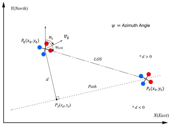
Figure 1.
The structure of the conventional LOS guidance method. (Red dots represent the front side as a quadrotor moves forward, and blue dots represent the back side of the quadrotor).
The Bézier curve can be estimated from a set of control points, including a starting point, terminal point, and shape-defined point. The Bézier curve method has been used in motion planning algorithms for autonomous vehicles in many studies [29]. In this work, we assume that the control points are the points that the target UAV has passed along the path. Thus, a Bézier curve of degree obtained from control points (, , , ) can be written as:
where:
The objectives of the LOS-based Bézier method are to generate a UAV path from a set of control points determined from the points that a target UAV passed and then use the LOS guidance system to command the UAV to move along the corresponding path. This method can guide UAVs to follow a target UAV and outperform conventional methods (e.g., the LOS technique). However, because the Bézier path is generated before guidance steps, this algorithm consumes more time than the conventional method. Figure 2 shows the results of experiments presented in previous work. Since the output of this method is a ground speed command from the LOS guidance system, this method can be used as the control input of the nonlinear KF.
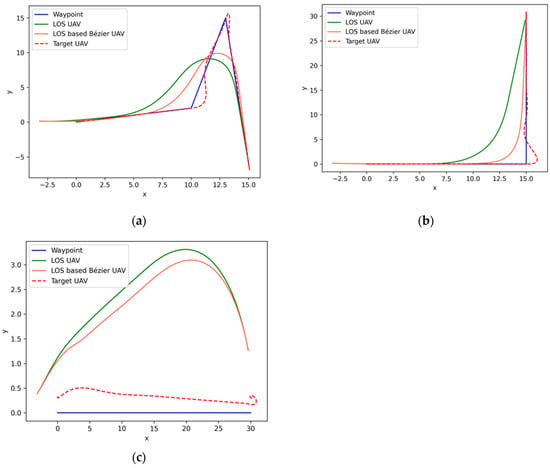
Figure 2.
The results of LOS-based Bézier simulation: (a) results of the LOS-based Bézier simulation; (b) results of the LOS-based Bézier method on a random flight path with a 90-degree turning flight path simulation; (c) results of the LOS-based Bézier method on a straight flight path with wind simulation.
2.3. Nonlinear Kalman Filter
A KF is a state estimation algorithm that generates unknown variables that tend to be more accurate than measurements observed over time [30]. KFs are used to estimate the state based on linear dynamic systems processed from time to time . The KF model assumes that the state vector at time evolves from the state vector at , as given in Equation (6):
where is the state transition model, which is multiplied by the state vector at the previous time ; is the control input model, which is multiplied by the control vector ; and is the process noise vector, which is assumed to be zero-mean Gaussian with covariance , and The observation or measurement of the state vector can be calculated as follows:
where is the observation model or measurement matrix at time and is the observation noise or measurement noise, which is assumed to be zero-mean Gaussian with covariance . and are typically used as tuning parameters for obtaining appropriate results.
The standard KF is used to solve linear problems, but most real-world systems are nonlinear [31]. For nonlinear state estimation in this paper, the EKF, UKF, and ENKF are introduced. Thus, the corresponding nonlinear state transition and observation models can be written as:
where is a function used to compute the predicted state at time from the previous estimation at time , and function is used to compute the predicted measurement from the predicted state.
An EKF can be efficiently used in nonlinear models, as in the studied problem, based on differentiation with a Jacobian matrix to reduce the mean square error of the estimates [32]. This work involves nonlinear dynamic models of UAVs and nonlinear measurement models based on GPS sensors and magnetometer sensors.
According to St-Pierre and Gingras [33], UKFs are used in nonlinear models with multiple types of sensor data in this work, including GPS sensor and magnetometer data. UKFs solve the approximation issues of EKFs by using a minimal set of cautiously chosen sample points [34]. In this work, sigma points and weights are calculated through an unscented transformation method [35] to capture high-order information about the considered distribution based on a very small number of points.
ENKF is a Monte Carlo approximation of KF [4], and it can avoid evolving the covariance matrix of the state vector. Conceptually, instead of reweighting in the update state, ENKF uses shifts, which allow the algorithm to remain stable in high-dimensional problems. ENKF uses a number of sigma points (ensemble, ) around hundreds to thousands of state vectors randomly sampled around an estimate and adds perturbations at each update and prediction step. During the initialization process, an ensemble of initial states is generated by drawing random samples from a multivariate normal distribution.
In this study, nonlinear KFs are state estimators that help a GPS sensor with a magnetometer to localize UAVs and then use those states to compute the UAV’s proper velocity and steering angle to utilize the proposed methods. State estimation using nonlinear KFs will be employed when the algorithm requests the UAV positions from the sensors as described in Section 3.3, Section 3.4 and Section 3.5. The states given by those sensors will be applied with nonlinear KFs to optimize localization performance and help localize UAVs when GPS is blocked in some areas.
2.4. Accuracy Assessment
The root mean square error (RMSE) is used for accuracy assessment in this paper. It is calculated in both the horizontal and vertical axis directions. It computes by using the positions estimated from the nonlinear KFs and the positions obtained from the API of the simulation program. According to Section 2.1, all APIs use the NED coordinate system . Thus, the RMSE in each direction is given by:
where is an exact NED coordinate location of a UAV obtained from the AirSim API controller and is a NED coordinate location of a UAV estimated by nonlinear KFs. Thus, the accuracy in 2D dimensions (horizontal axis) and 3D dimensions (horizontal and vertical axes) can be calculated using the equations below:
3. Materials and Methods
This section describes the methods used in the experiment, including the simulation procedure for each experiment. The dynamic model of UAVs that is used for nonlinear KFs is explained in Section 3.1. The measurement model, which includes an AirSim GPS sensor and magnetometer, is described in Section 3.2. These models are used in the localization state process with three types of nonlinear KFs for a follower UAV, with the control input provided by the LOS-based Bézier algorithm, which is described in Section 3.3. The proposed rendezvous method is presented in Section 3.4. The full mission state is explained in Section 3.5.
3.1. Kinematic Model
This research considers the movement of UAVs in both the horizontal plane and the vertical plane because, unlike cars, UAVs can move vertically. The kinematic model of UAVs includes position and velocity variables. Therefore, we assume that the state vector of a UAV in six dimensions is , where is the position vector of a UAV in relation to the NED coordinate system in AirSim, according to [27]. is the velocity vector of a UAV in relation to the coordinate system in AirSim. Thus, the discrete-time dynamic UAV model is given by the following equations:
where is the value of the continuous time state vector at time and and are the velocity control vectors of the UAV, which are given by the output of the LOS guidance-based Bézier algorithm in Section 2.2. According to the KF theory discussed in Section 2.3, the transition matrix and input control model can be written as:
Therefore, the discrete-time dynamic model of a UAV can be written as shown in the following equation:
3.2. Measurement Model
The measurement model used in this study is based on a GPS sensor simulated in AirSim in terms of latitude, longitude and elevation information. Geodetic coordinates, such as latitude, longitude, and elevation, can be converted to the NED coordinates used in AirSim by transforming the geodetic coordinates into Earth-fixed (ECEF) coordinates [36]. Then, the ECEF coordinates are converted into the NED coordinates used in AirSim. The conversion of geodetic coordinates (latitude , longitude , height ) to ECEF coordinates () can be expressed as follows:
where:
In the above equations, a is the equatorial radius, and is the square of the first numerical eccentricity of an ellipsoid. The variables used in AirSim are set as and . Thus, the NED coordinates in AirSim can be calculated from the ECEF coordinates given by the functions and the geodetic coordinates of geopoints in AirSim (geopoint latitude , geopoint longitude , and geopoint height ) as follows:
where is defined as the angle in the Euclidean plane, given in radians, between the positive x-axis and the ray to the point [37], and is the measurement equation for a GPS sensor. In AirSim, we consider the original geopoint to be , , and , which is the default setting in AirSim [27]. Another measurement equation set in the experiment is the cumulative travel distance as follows:
where is the value of the time state vector at time . and are the velocity vectors of a UAV in relation to the coordinate system in AirSim. is the value of the continuous-time state vector at time . Thus, it can be written as:
Now, we consider the second sensor, which is a magnetometer. As noted in Section 2.1, AirSim includes a realistic magnetic field. Thus, a magnetometer was attached to the UAV to measure the magnetic field and the bearing angle of the UAV. As reported by Shah et al. [38], the output of the magnetometer is produced in relation to the body frame of the UAV, and the UAV is simulated in relation to the AirSim world. Thus, the bearing angle of the UAV is given as follows:
where and are the strengths of the magnetic field in the north and east directions or and directions in the NED coordinate system, respectively. Therefore, the measurement equation for this sensor can be written as:
To avoid a particular case where , the measurement equation can be rewritten as:
In summary, the equation for the combined GPS and magnetometer measurements is given as:
3.3. Localization State Processes
The processes for localization state refer to the processes to work with the area outside of the sky-blue circle in Figure 3. The localization method is described below in Algorithm 1. The process begins by connecting the API and AirSim and setting all initial conditions for the nonlinear KF, including the tuning parameter. Then, iterative commands are applied for the UAV to move following a target UAV along a given waypoint sequence. The iteration process starts with planning the path from the set of control points (), which includes the points that the target UAV passes, based on the Bézier curve method described in Section 2.2. is a tuning parameter in the LOS-based Bézier algorithm. Consequently, a new set of control points is collected from the target UAV and used to control the following UAV movements based on the LOS-based Bézier method, which is used as the control input () of the nonlinear KFs. The next step is obtaining a GPS sensor value and magnetometer sensor data for nonlinear Kalman processing. The two test cases can be established from this localization state, namely, the all-available GPS signal (full-GPS-signal) case and blocked GPS signal case. For a blocked GPS signal, the KF’s tuning parameters and are reset for a blocked GPS signal situation. Finally, all of these datasets are input into a kinematic model and a measurement model with three types of nonlinear KFs, and the results are compared.
| Algorithm 1: Simulation Procedure for Localization |
|
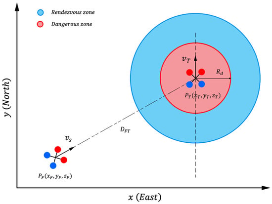
Figure 3.
Geometry used in the rendezvous UAV method. (Red dots represent the front side as a quadrotor moves forward, and blue dots represent the back side of the quadrotor).
3.4. Proposed Rendezvous State Processes
A proposed rendezvous method guides a following UAV moving toward the target UAV based on the heading angle estimation resulting from LOS guidance and position estimation by nonlinear KFs. The processes work based on considering the relative velocity and displacement between the two UAVs. The proposed rendezvous state processes apply to the sky-blue and red areas in Figure 3, which are separated into a rendezvous zone and a dangerous zone. Algorithm 2 and Figure 4 describe the simulation procedure of the proposed rendezvous method, which command a UAV via conventional LOS guidance alone. The position and velocity of the target UAV are obtained and the output is given as the proper velocity vector from the conventional LOS guidance based on the displacement and position of the UAVs at that time to steer the follower UAV. The experiment implements nonlinear KFs with an offline dynamic dataset exported from AirSim and keeps the data from the magnetometer and GPS sensor as the measurement parameters. As mentioned, the proposed rendezvous processes deploy the relation between velocity and displacement to define a setting parameter for the flight controller to command UAV movement.
| Algorithm 2: Simulation Procedure of the Rendezvous Method |
|
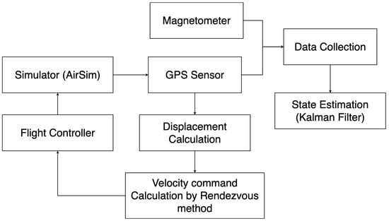
Figure 4.
Block diagram of the rendezvous state simulation procedure.
The proposed rendezvous strategy applies a displacement condition for the UAV velocities. The higher the velocity of the target UAV is, the higher the velocity of the follower. In far displacement between 2 UAVs, the LOS-based Bézier method can provide excellent performance in path planning. However, only LOS guidance is recommended in the case of two UAVs approaching or in a rendezvous state because it is a short distance and does not require complex processes and has limited time. The displacement between UAVs () can be computed as follows:
where is the position of the following UAV and is the position of the target UAV, which is provided by the GPS sensor and then converted to the NED coordinate system of AirSim, as described in Section 3.2. The position of the follower UAV is computed based on the localization method in Section 3.3. After computing the displacement between UAVs, the ground speed of the follower UAV () can be computed using Equation (38), which is based on the linear relation between the displacement of UAVs and the velocity of the target UAV.
where is the maximum approach speed of the follower UAV and is the velocity of the target UAV. We assume that . The LOS angle between UAVs is calculated from Equation (1) with and information. Then, the horizontal command velocity () is calculated with Equations (2) and (3) based on and . Finally, the follower UAV is controlled based on a command velocity to follow the target UAV with minimum displacement between them, and the obtained position estimation data are used by the nonlinear KFs for state estimation.
3.5. The Proposed Full Mission State Processes
A full mission state is implemented when the distance between two UAVs from the starting point is large. Switching between the localization state and rendezvous state strategy will be applied, as shown in both the inside and outside of the circle in Figure 3. A full mission state is a mission in which a follower UAV tries to follow a target UAV while maintaining minimum displacement between them and avoiding collisions. The rendezvous state strategy from Section 3.4 can be used for the entire mission. However, to fully utilize, the experiment separates into: (1) the localization state using the LOS-based Bézier guidance systems and (2) the rendezvous state, which uses the conventional LOS guidance. When the follower UAV is outside the rendezvous zone, the LOS-based Bézier will be applied. Otherwise, the conventional LOS guidance method will be applied. In summary, instead of using a single motion planning method like Algorithm 1 or Algorithm 2, the full mission state adapts between two motion planning methods using the results previously discussed in Section 2.2 [14].
The proposed full mission state method is presented in Figure 5. It switches between the localization state processes, as discussed in Section 3.3 and the proposed rendezvous state processes, as discussed in Section 3.4. The localization state processes deal with long distances of UAVs. The proposed rendezvous state processes work when the distance between UAVs is closer or inside the circle area, as shown in Figure 3. The distance can be computed from the displacement equation expressed in Equation (37). Algorithm 3 presents the procedure for the proposed full mission state processes. The processes were implemented with dynamic offline data exported from AirSim, and the data from the magnetometer and GPS sensor were used as measurement parameters, as mentioned in the proposed rendezvous state processes. However, it has a procedure to check that the following UAV is entering the rendezvous zone or sky-blue zone in Figure 3. After checking, the processes will decide to use the localization state processes or the proposed rendezvous state processes to command the UAV.
| Algorithm 3: Simulation Procedure for a Full Mission State |
|
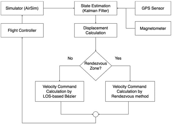
Figure 5.
Block diagram of the proposed full mission state simulation procedure.
4. Simulation Results
The simulation of the three-state experiment was performed on a laptop equipped with a 2.9 GHz dual-core Intel Core i5 CPU with Intel Iris Graphics 550 and 8 GB of memory. The API control, which is used to interact with AirSim, was written in the Python programming language. Since the altitude of a UAV is negative in the Z direction, as described in Section 2.1, the altitude of a UAV obtained from the API will be converted from a negative number to a positive number to make the result easier to read and analyze. In this section, the results obtained from the processes in Section 3.3, Section 3.4 and Section 3.5 are explained, and organized as follows:
- -
- Section 4.1 presents the simulation results for the localization state processes (following the process in Section 3.3), which include the situation of the full GPS signal available case in Section 4.1.1 and the situation of the blocked GPS signal in Section 4.1.2.
- -
- Section 4.2 presents the simulation results of the proposed rendezvous state method by following the method proposed in Section 3.4.
- -
- Section 4.3 presents the simulation results for the proposed full mission state processes (referring to the process in Section 3.5).
- -
- Section 4.4 presents the result from implementing the proposed full mission state process (referring to the process in Section 3.5) for two UAVs.
Note that all raw data from the GPS sensor have Gaussian distribution noise with a mean of zero and standard deviation of 0.15 to increase the practicality of GPS sensor data.
4.1. Localization State Results
For the localization state, the experiments include two cases: (1) a full-power GPS signal and (2) weak GPS signals in disturbed areas. These two cases affect position estimation performed by nonlinear KFs. The LOS-based Bézier method is applied to control the inputs of the nonlinear KFs. In this experiment, AirSim is used to perform a simulation of two UAVs, the follower UAV and target UAV. The target UAV moves along the waypoints WP1 (0, 7), WP2 (10, 9), WP3 (13, 25), and WP4 (15, 1) and starts at WP1 at an altitude of 7 m. The target UAV is moved through API control in AirSim at a ground speed of 2 m per second. The follower UAV is controlled at a command velocity obtained from the localization state processes with the initial speed () at 1 m per second setting by API control. The data from the GPS sensor and magnetometer of both the follower UAV and target UAV are collected from AirSim with a 1 Hz GPS sensor. The AirSim API, which is written in the Python programming language, is used to collect actual flight data. The tuning parameter of the LOS-based Bézier method () was set to 2 for both the full-GPS-signal case and blocked-signal experiments. The initial state of the follower UAV in both experiments was set as follows:
4.1.1. Full GPS Signal Result
In this experiment, the GPS worked normally without signal blockage issues. The tuning parameters of the nonlinear KFs R and Q were considered as follows:
where and are used for the UKF and ENKF, respectively, and and are used for the EKF.
According to Figure 6 and Figure 7, which illustrate the position estimation results of this experiment, the nonlinear KFs provide very impressive results and corresponding with Table 1, the accuracy of positioning based on all algorithms is shown. The most accurate position estimates are provided by the ENKF with the lowest RMSE of at 0.21686 m, followed by those of the UKF (RMSE of m) and EKF (RMSE of m). Overall, all the nonlinear KFs provided higher accuracy than methods based only on using GPS sensor data (RMSE of m).
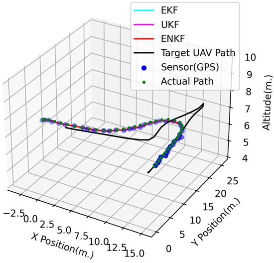
Figure 6.
3D UAV positions in the full-GPS-signal experiment.
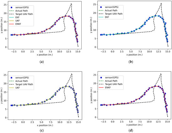
Figure 7.
2D UAV positions in the full GPS signal experiment results: (a) GPS data comparison with nonlinear KFs; (b) GPS data comparison with an EKF; (c) GPS data comparison with a UKF; (d) GPS data comparison with an ENKF.

Table 1.
RMSE estimates from the EKF, UKF, ENKF, and GPS sensor data for both full-signal and blocked-signal flight cases.
4.1.2. Blocked GPS Signal Result
In this experiment, the GPS signal was blocked or lost for some time. The tuning parameters are modified to rely on the system model more than the measurements. Thus, the process and measurement noise covariance during the loss of GPS signal data can be rewritten as follows:
where is used for all nonlinear KFs when the GPS signal is lost.
Figure 8, Figure 9 and Figure 10 show the 3D and 2D position estimations of the follower UAV. Even if the GPS signal is blocked for a period of time, all nonlinear KFs are able to estimate the state or position with acceptable accuracy. In addition, the highest accuracy in this experiment is achieved with the ENKF by an RMSE of equal to 0.29538 m, followed by the UKF (RMSE of m) and EKF (RMSE of m), as shown in Table 1.
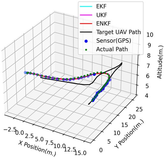
Figure 8.
3D UAV positions in the blocked GPS signal experiment.
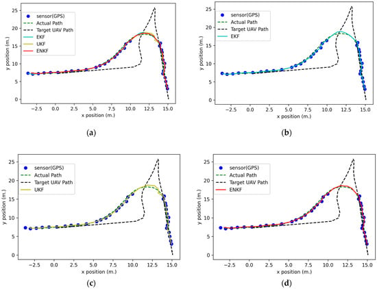
Figure 9.
2D UAV positions in the blocked GPS signal experiment results: (a) GPS data comparison with nonlinear KFs; (b) GPS data comparison with an EKF; (c) GPS data comparison with a UKF; (d) GPS data comparison with an ENKF.
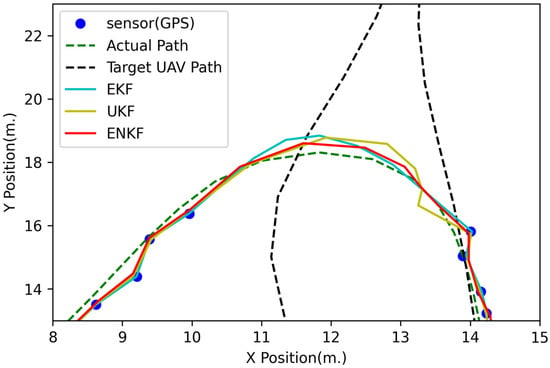
Figure 10.
Zoomed 2D positions in the blocked GPS signal case.
Normally, at least four satellites are needed to extract the position or location. This concept can be used as a trigger or threshold to switch the parameters of state estimation between the GPS available and GPS outage situation. In real-world applications, some drone kit libraries provide a function to check the number of satellites [39] to calculate a location. Moreover, state estimation can work in GPS outage situations in short periods of time, as shown in Figure 10, depending on the system model. However, it still needs the GPS signal for updating in the next time step.
4.2. Rendezvous State Results
This experiment focuses on the case of the follower UAV approaching the target UAV and getting as close as possible while avoiding collisions based on the proposed rendezvous method described in Section 3.4. The target UAV moves along the waypoints from WP1 (0, 7) to WP2 (0, 100) at a constant velocity () of 2 m per second and an altitude of 7 m. In addition, the initial conditions of the follower UAV are as follows:
where () is the position of the follower UAV in the NED coordinate system in AirSim, () is the velocity of the follower UAV, R and Q are used for the ENKF, and are used for the UKF, and and are used for the EKF. The follower UAV can move at the maximum approach speed () in the approach state, which is 2.5 m per second. The dangerous zone () is set equal to 3 m around the target UAV. The rendezvous zone is 6 m around the target UAV. For the rendezvous state experiment, the follower UAV is already in the rendezvous zone at the start of the simulation, as shown in Figure 3. The state estimation strategy for the follower UAV is the same as that considered in the localization state approach described in Section 4.1. The positioning information for the target UAV is provided by a 1 Hz GPS sensor. The position estimation result is shown in Figure 11. According to Figure 12, the follower UAV tries to follow the target with minimum displacement and without collisions. The follower UAV can reach the dangerous zone in 12 s at point (−0.36378, 26.12666) and an altitude of 6.91099 m based on only GPS sensor data, at point (−0.36889, 26.12615) and an altitude of 6.91126 m based on the EKF, at point (−0.36378, 26.18720) and an altitude of 6.91101 m based on the UKF, and in 11 s at point (−0.57952, −0.57952) and an altitude of 6.91901 m based on the ENKF. The UAV then attempted to stay as close to the dangerous zone as possible without entering the zone. Table 2 provides the RMSE of the results after the follower UAV enters the dangerous zone (3 m around the target UAV) and the time when the follower UAV reaches the dangerous zone. Table 2 shows that the ENKF can achieve the best result, with an RMSE of equal to 3.00275 m. Figure 13 shows the velocity results for the following UAVs and indicates that the follower quickly accelerates to the maximum approach speed from time at 1 s to 10 s to follow the target UAV and minimize displacement. After 10 s, the follower UAV decelerates and maintains a relatively constant speed to maintain a constant displacement distance.
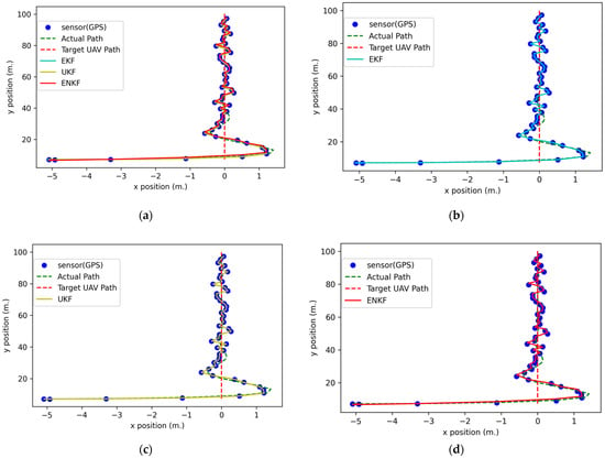
Figure 11.
The 2D positions in the rendezvous state simulation: (a) GPS data comparison with nonlinear KFs; (b) GPS data comparison with an EKF; (c) GPS data comparison with a UKF; (d) GPS data comparison with an ENKF.
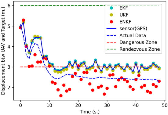
Figure 12.
The displacement between the follower UAV and target UAV in the rendezvous state simulation.

Table 2.
RMSE of XYZ results after the follower UAV enters the dangerous zone and the time when the follower UAV reaches the dangerous zone in the rendezvous state simulation.
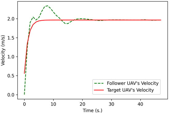
Figure 13.
Comparison of the velocities of the follower UAV and target UAV in the rendezvous state simulation.
4.3. The Proposed Full Mission State Results
For the full mission state simulation, the path of the target UAV is set to include a long 90-degree turn in the middle, as shown in Figure 14. Thus, the target UAV moves along waypoints WP1 (0, 7) to WP2 (0, 150) and then to WP3 (−100, 150) at an altitude of 7 m. The target UAV is controlled by API control in AirSim at a velocity of 2 m per second. The follower UAV follows the target UAV by using the proposed full mission state processes (described in Section 3.5) based on the following initial conditions:
where () is the position of the follower UAV in the NED coordinate system in AirSim and () is the velocity of the follower UAV. Because there are two different states, namely, outside and inside of the rendezvous zone, as shown in Figure 3, the tuning parameters of KFs () are separated into two groups as follows:
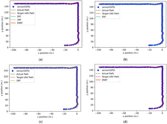
Figure 14.
The 2D positions in the full mission state simulation: (a) GPS data comparison with nonlinear KFs; (b) GPS data comparison with an EKF; (c) GPS data comparison with a UKF; (d) GPS data comparison with an ENKF.
- Outside rendezvous zone
- Inside rendezvous zone
The maximum ground speed () of the follower UAV is set to 3 m per second in the localization state in this experiment. GPS sensors on both UAVs are assumed to operate at 1 Hz. The radius of the rendezvous zone is 6 m to provide enough space, which has been tested to be enough for the follower UAV to slow safely at this speed. The larger the rendezvous zone radius, the safer this algorithm can perform, which depends on many factors, such as the performance of the UAV, the maximum speed, and the environment. Therefore, this work only focuses on how the algorithm performs within the scope of this limitation. If the following UAV is outside of the rendezvous zone radius, the localization processes, which include the LOS-based Bézier method by setting the tuning parameter of the LOS-based Bézier method () to 3 in this experiment, will be applied. After the follower UAV enters the rendezvous zone, the follower UAV is operated according to the proposed rendezvous method described in Section 3.4. The dangerous zone () is set at 3 m around the target UAV in this experiment, and the maximum approach speed () of the follower UAV is set to 2.5 m per second.
Figure 15 and Figure 16 show the results of the full mission state. Figure 15 shows the result of displacement between the UAVs in each time frame. The follower UAV uses the localization method initially until it enters the rendezvous zone after approximately 19 s. Then, the rendezvous method is used to command the following UAV toward the target UAV. After approximately 70 and 80 s, the target UAV turns 90 degrees following the designated path, as shown in Figure 14. During the turn, the target UAV decreases its speed to almost 1 m per second, as shown in Figure 16. Thus, the follower UAV decreases its speed to almost 0.5 m per second and then accelerates to the same speed as the target UAV. The results indicate that the proposed rendezvous method can guide the follower UAV to the rendezvous zone and aid in the approach of the dangerous zone in 22 s (Table 3) at point (0.47686, 51.74109) and an altitude of 6.83795 m based on GPS sensor data only, at point (0.47795, 51.74018) and an altitude of 6.83779 m based on the EKF, at point (0.49439, 51.72599) and an altitude of 6.83809 m based on the UKF, and at point (0.48511, 51.76452) and an altitude of 6.83052 m based on the ENKF. The accuracy assessment of this experiment is separated into two parts, namely, the RMSE of XYZ outside the rendezvous zone and the RMSE of XYZ inside the rendezvous zone, as presented in Table 3. The ENKF performs better than the others both inside, with an RMSE of XYZ at 0.51319 m, and outside the rendezvous zone (RMSE of XYZ at 0.75051 m). The RMSEs in this experiment are higher than those in other experiments because there is a 90-degree turn in the flight path of the target UAV. However, for a very short time, the displacement between UAVs is less than that of the dangerous zone radius. This experiment illustrates that even if the target UAV turns 90 degrees and decelerates, the proposed rendezvous method can still track the target UAV without a collision occurring. From Table 2 and Table 3, the RMSEs of nonlinear KFs are higher than those for the method based only on GPS sensor data because some parameters can be tuned to achieve higher performance.
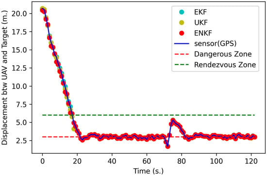
Figure 15.
The displacement between the follower and target UAVs in the full mission state simulation.
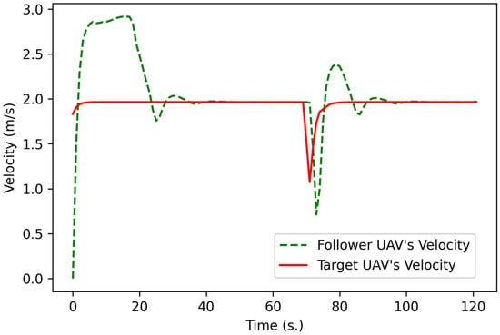
Figure 16.
Comparison of the velocities of the follower UAV and target UAV in the full mission state simulation.

Table 3.
RMSE of the follower UAV in three dimensions and the time when the follower UAV reaches the dangerous zone in the full mission state experiment.
4.4. Implementation of the Proposed Full Mission State Process
In this section, the proposed full mission state processes have been implemented with two UAVs that have a simple specification as follows:
- Pixhawk 4 Mini
- Frame: Holybro QAV250
- Holybro Telemetry Radio V3
- Motors—DR2205 KV2300
- 5″ Plastic Props
- Holybro GPS Neo-M8N
- Battery: MEGA POWER 3S 11.1 V 2200 mAh
- Fr-sky D4R-ii receiver
- Flysky FS-i6 Flight controller
The experiment for real implement deploys an on-board state estimation in Pixhawk 4 Mini. In the mission, the target UAV flies as a setting waypoint, and the following UAV always detects the position of the target UAV and calculates the heading angle to the command direction. The proposed full mission state processes are deployed in the following UAV. Therefore, the following UAV will detect and recognize the position and zone to adjust the velocity to prevent the collision event.
Figure 17 shows a block diagram of the real implementation of the proposed full mission state processes, and the results regarding the position of the target and follow UAV are presented in Figure 18, while their velocity is presented in Figure 19. A video of the real implementation is available at “www.tinyurl.com/2p8bj8sc (accessed on 20 May 2022)”. In real implementation, it has other parameters that are not included in the simulation, such as the wind effect. Therefore, the positions of the UAVs in Figure 18 do not exactly match between the follower UAV and the target UAV. However, both UAVs can work without collision depending on the radius of the dangerous zone () and the velocity of the target UAV () that has been used to calculate the command velocity of the follower UAV () as presented in Figure 17, which is considered to complete the aim of this research. Because there still is a chance of collision when the target is moving very fast, the () parameter must be optimized to match () dynamically or manually to generate a safer operation, which can be extended in subsequent work.
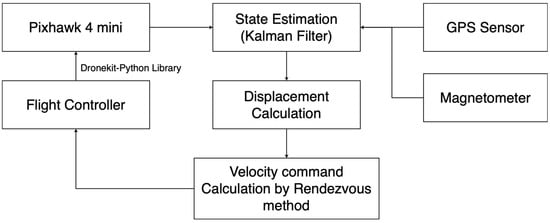
Figure 17.
Real implementation block diagram of the rendezvous strategy.
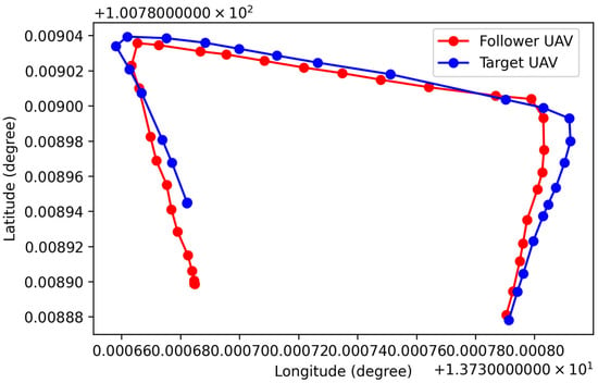
Figure 18.
The 2D positions of the real implementation of the proposed full mission state strategy.
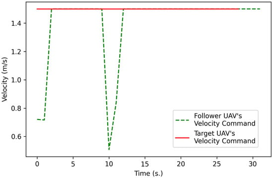
Figure 19.
Comparison of the velocities of the follower UAV and target UAV in the real implementation of the proposed rendezvous strategy.
5. Discussion
UAVs have been utilized in several proposed and different environments. For example, UAVs are used in cinematography [40], or deployed under threats, which has a primary goal of finding optimal routes that consider target visit, threat exposure, and travel time [41,42]. However, no matter the UAV application, UAV path planning to avoid conflict among UAVs is very important. [43] implements an artificial moment method for conflict resolution with robots being close to their targets. [44] implements a cooperative and geometric learning algorithm for path planning. [45] improve high performance path planning by considering a control-oriented UAV. In this experiment, trajectory planning for multiple UAVs was developed based on a sequential Monte Carlo method, which was testing using GPS always available and GPS lost scenarios with some time and separation for a rendezvous zone and dangerous zone to calculate the relevant parameters to control the UAV. Therefore, the proposed method has presented another aspect and contributes to UAV path planning. The proposed method also tests a real situation as mentioned in Section 4.4 and illustrates satisfactory results. For future work, a parameter-tuning method and other factors, such as wind effects in the dynamic model, should be included to enable the proposed method to achieve higher performance.
6. Conclusions
This study presents a comparison of different types of nonlinear KFs, including an EKF, a UKF, and an ENKF, with offline UAV dynamic data exported from AirSim and applies combined GPS data and magnetometer data as a measurement model. The experiment contains three cases, namely, localization, the proposed rendezvous strategy, and the proposed full mission strategy. The localization state includes two test cases, namely, a GPS outage in some areas and a fully available GPS signal. The RMSE is used as an accuracy assessment by computing the RMSE between the actual flight position obtained from the API of AirSim and the position estimates of different types of nonlinear KFs.
The procedure in the localization state includes the LOS-based Bézier method for heading angle estimation and nonlinear KFs for position estimation. The result for the localization state shows that even when GPS outages occur in some areas, nonlinear KFs are able to estimate the state of UAVs with higher accuracy than methods based only on GPS sensor data.
The proposed rendezvous method allows a follower UAV to safely approach a moving target UAV without collision. Additionally, the proposed rendezvous method maintains the displacement distance during flight. The proposed rendezvous strategy works based on the relationship between velocity and displacement distance through setting the area, namely, the rendezvous zone and dangerous zone. The nonlinear KFs are implemented for position estimation, while the LOS method is used for heading angle estimation. The performance in the rendezvous state shows that the ENKF is exceptional.
Finally, the proposed full mission state strategy is to control the follower UAV at the minimum displacement distance from the target UAV while minimizing the time consumption and avoiding collisions. The proposed full mission state strategy has to work inside and outside of the rendezvous zone, as shown in Figure 3. Therefore, the localization state method applies to the outside rendezvous zone, and the proposed rendezvous processes apply to the inside rendezvous zone. The results present two sets of RMSE inside and outside the rendezvous zone. Similar to the proposed rendezvous strategy results, the ENKF illustrates the best performance.
Furthermore, the real implementation has been done with simple specification UAVs and using an onboard state estimation in Pixhawk 4 Mini flight controller illustrated in “www.tinyurl.com/2p8bj8sc (accessed on 20 May 2022)”. The real implementation is proof that the proposed full mission state strategy can be truly operated.
This research provides a useful approach for UAV traffic management and other kinds of autonomous vehicle traffic management. This work can also contribute to the two main challenge objectives mentioned in the introduction, namely the UAV docking operation to recharge and swarm UAV missions to reduce operating space and prevent collisions between UAVs, such as parcel delivery missions.
Future research will include studying other effects in the simulation, such as the wind effect, which will allow the proposed rendezvous method to have higher performance. Other subsystems, such as communication systems and energy systems, that will contribute to long-term flight are also included in future research plans.
Author Contributions
Conceptualization, P.K., W.H. and P.T.; methodology, W.H. and P.K.; software, W.H. and P.K.; validation, W.H., P.K. and T.P.; formal analysis, W.H. and P.K.; investigation, W.H. and P.K.; resources, P.K. and T.P.; data curation, W.H. and P.K.; writing—original draft preparation, W.H.; writing—review and editing, W.H., T.J., P.K. and T.S.; visualization, W.H., P.K.; supervision, P.K. and P.T.; project administration, P.K.; funding acquisition, P.K. All authors have read and agreed to the published version of the manuscript.
Funding
This work is supported by King Mongkut’s Institute of Technology Ladkrabang [grant number KREF046603 and 2565-02-18-001].
Data Availability Statement
The data presented in this study are available on request from the corresponding author. The data is not publicly available due to the permission of data sharing policy.
Acknowledgments
The authors would like to thank Xu Wei and Peerapong Torteeka, who acknowledges the President’s International Fellowship Initiative of the Chinese Academy of Sciences (Grant code: 2023VEC0009) for support this work.
Conflicts of Interest
The authors declare no conflict of interest.
References
- Hassanalian, M.; Abdelkefi, A. Classifications, applications, and design challenges of drones: A Review. Prog. Aerosp. Sci. 2017, 91, 99–131. [Google Scholar] [CrossRef]
- Shakhatreh, H.; Sawalmeh, A.H.; Al-Fuqaha, A.; Dou, Z.; Almaita, E.; Khalil, I.; Othman, N.S.; Khreishah, A.; Guizani, M. Unmanned Aerial Vehicles (uavs): A survey on civil applications and key research challenges. IEEE Access 2019, 7, 48572–48634. [Google Scholar] [CrossRef]
- Ghamry, K.A.; Kamel, M.A.; Zhang, Y. Multiple uavs in forest fire fighting mission using particle swarm optimization. In Proceedings of the 2017 International Conference on Unmanned Aircraft Systems (ICUAS), Miami, FL, USA, 13–16 June 2017. [Google Scholar] [CrossRef]
- Nichols, J.W.; Sun, L.; Beard, R.W.; McLain, T. Aerial rendezvous of small unmanned aircraft using a passive towed cable system. J. Guid. Control Dyn. 2014, 37, 1131–1142. [Google Scholar] [CrossRef]
- Wilson, D.; Goktogan, A.; Sukkarieh, S. Guidance and navigation for UAV Airborne Docking. In Robotics: Science and Systems XI; Sapienza University of Rome: Rome, Italy, 2015. [Google Scholar] [CrossRef]
- Park, S. Rendezvous guidance on circular path for fixed-wing UAV. Int. J. Aeronaut. Space Sci. 2020, 22, 129–139. [Google Scholar] [CrossRef]
- Antony, A.; Sivraj, P. Food Delivery Automation in restaurants using collaborative robotics. In Proceedings of the 2018 International Conference on Inventive Research in Computing Applications (ICIRCA), Coimbatore, India, 11–12 July 2018. [Google Scholar] [CrossRef]
- Yang, L.; Qi, J.; Xiao, J.; Yong, X. A literature review of UAV 3D path planning. In Proceedings of the 11th World Congress on Intelligent Control and Automation, Shenyang, China, 29 June–27 July 2014. [Google Scholar] [CrossRef]
- Zhao, Y.; Zheng, Z.; Liu, Y. Survey on computational-intelligence-based UAV path planning. Knowl. -Based Syst. 2018, 158, 54–64. [Google Scholar] [CrossRef]
- Coutinho, W.P.; Battarra, M.; Fliege, J. The unmanned aerial vehicle routing and trajectory optimisation problem, a taxonomic review. Comput. Ind. Eng. 2018, 120, 116–128. [Google Scholar] [CrossRef]
- Gans, N.; Dixon, W.; Lind, R.; Kurdila, A. A hardware in the loop simulation platform for vision-based control of Unmanned Air Vehicles. Mechatronics 2009, 19, 1043–1056. [Google Scholar] [CrossRef]
- Shah, S.; Dey, D.; Lovett, C.; Kapoor, A. AirSim: High-fidelity visual and physical simulation for Autonomous Vehicles. In Field and Service Robotics, Proceedings of the 11th Conference on Field and Service Robotics, Zürich, Switzerland, 13–15 September 2017; Springer: Cham, Switzerland, 2017; pp. 621–635. [Google Scholar] [CrossRef]
- Farhad, M.A.; Mosavi, M.R.; Abedi, A.A. Fully adaptive smart vector tracking of weak GPS signals. Arab. J. Sci. Eng. 2021, 46, 1383–1393. [Google Scholar] [CrossRef]
- Hematulin, W.; Kamsing, P.; Torteeka, P.; Somjit, T.; Phisannupawong, T.; Jarawan, T. Cooperative Motion Planning for multiple uavs via the Bézier curve guided line of sight techniques. In Proceedings of the 2021 23rd International Conference on Advanced Communication Technology (ICACT), PyeongChang Kwangwoon Do, Republic of Korea, 13–16 February 2021. [Google Scholar] [CrossRef]
- Ingersoll, B.T.; Ingersoll, J.K.; DeFranco, P.; Ning, A. UAV path-planning using bezier curves and a receding horizon approach. In Proceedings of the AIAA Modeling and Simulation Technologies Conference, Washington, DC, USA, 13–17 June 2016. [Google Scholar] [CrossRef]
- Velez, P.; Certad, N.; Ruiz, E. Trajectory generation and tracking using the ar.drone 2.0 Quadcopter UAV. In Proceedings of the 2015 12th Latin American Robotics Symposium and 2015 3rd Brazilian Symposium on Robotics (LARS-SBR), Uberlandia, Brazil, 29–31 October 2015. [Google Scholar] [CrossRef]
- Lopez-Sanchez, I.; Rossomando, F.; Pérez-Alcocer, R.; Soria, C.; Carelli, R.; Moreno-Valenzuela, J. Adaptive trajectory tracking control for quadrotors with disturbances by using generalized regression neural networks. Neurocomputing 2021, 460, 243–255. [Google Scholar] [CrossRef]
- Moreno-Valenzuela, J.; Perez-Alcocer, R.; Guerrero-Medina, M.; Dzul, A. Nonlinear PID-type controller for quadrotor trajectory tracking. IEEE/ASME Trans. Mechatron. 2018, 23, 2436–2447. [Google Scholar] [CrossRef]
- Zhang, P.; Gu, J.; Milios, E.; Huynh, P. Navigation with IMU/GPS/digital compass with unscented Kalman filter. In Proceedings of the IEEE International Conference Mechatronics and Automation, Niagara Falls, ON, Canada, 29 July–1 August 2005. [Google Scholar] [CrossRef]
- Work, D.B.; Tossavainen, O.-P.; Blandin, S.; Bayen, A.M.; Iwuchukwu, T.; Tracton, K. An ensemble Kalman filtering approach to highway traffic estimation using GPS enabled mobile devices. In Proceedings of the 47th IEEE Conference on Decision and Control, Cancun, Mexico, 9–11 December 2008. [Google Scholar] [CrossRef]
- Gupta, A.; Fernando, X. Simultaneous localization and mapping (SLAM) and data fusion in unmanned aerial vehicles: Recent advances and challenges. Drones 2022, 6, 85. [Google Scholar] [CrossRef]
- Yi, S.; Zorzi, M. Robust kalman filtering under model uncertainty: The case of degenerate densities. IEEE Trans. Autom. Control 2022, 67, 3458–3471. [Google Scholar] [CrossRef]
- Koenig, N.; Howard, A. Design and use paradigms for gazebo, an open-source multi-robot simulator. In Proceedings of the 2004 IEEE/RSJ International Conference on Intelligent Robots and Systems (IROS) (IEEE Cat. No.04CH37566), Sendai, Japan, 28 September–2 October 2004. [Google Scholar] [CrossRef]
- Meyer, J.; Sendobry, A.; Kohlbrecher, S.; Klingauf, U.; Von Stryk, O. Comprehensive simulation of quadrotor uavs using ROS and Gazebo. In Lecture Notes in Computer Science; Springer Science and Business Media LLC: Berlin/Heidelberg, Germany, 2012; Volume 7628, pp. 400–411. [Google Scholar] [CrossRef]
- Furrer, F.; Burri, M.; Achtelik, M.; Siegwart, R. RotorS—A modular gazebo MAV Simulator Framework. In Studies in Computational Intelligence; Springer: Berlin/Heidelberg, Germany, 2016; pp. 595–625. [Google Scholar] [CrossRef]
- Robot Operating System (No Date) ROS. Available online: https://www.ros.org/ (accessed on 2 January 2023).
- AirSim AirSim Microsoft Open Source. Available online: https://microsoft.github.io/AirSim (accessed on 2 January 2023).
- Caharija, W.; Pettersen, K.Y.; Bibuli, M.; Calado, P.; Zereik, E.; Braga, J.; Gravdahl, J.T.; Sorensen, A.J.; Milovanovic, M.; Bruzzone, G. Integral line-of-sight guidance and control of underactuated marine vehicles: Theory, simulations, and experiments. IEEE Trans. Control Syst. Technol. 2016, 24, 1623–1642. [Google Scholar] [CrossRef]
- Choi, J.-W.; Curry, R.; Elkaim, G. Path planning based on Bézier curve for autonomous ground vehicles. In Proceedings of the Advances in Electrical and Electronics Engineering—IAENG Special Edition of the World Congress on Engineering and Computer Science 2008, San Francisco, CA, USA, 22–24 October 2008. [Google Scholar] [CrossRef]
- Condomines, J.P. Nonlinear Kalman Filtering for Multi-Sensor Navigation of Unmanned Aerial Vehicles; Elsevier: Amsterdam, The Netherlands, 2018. [Google Scholar] [CrossRef]
- Mao, G.; Drake, S.; Anderson, B.D. Design of an extended Kalman filter for UAV localization. In Proceedings of the 2007 Information, Decision and Control, Adelaide, SA, Australia, 12–14 February 2007. [Google Scholar] [CrossRef]
- Kallapur, A.; Anavatti, S. UAV linear and nonlinear estimation using extended Kalman filter. In Proceedings of the 2006 International Conference on Computational Inteligence for Modelling Control and Automation and International Conference on Intelligent Agents Web Technologies and International Commerce (CIMCA’06), Sydney, NSW, Australia, 8 January 2007. [Google Scholar] [CrossRef]
- St-Pierre, M.; Gingras, D. Comparison between the unscented Kalman filter and the extended Kalman filter for the position estimation module of an Integrated Navigation Information System. In Proceedings of the IEEE Intelligent Vehicles Symposium, Parma, Italy, 14–17 June 2004. [Google Scholar] [CrossRef]
- Wan, E.A.; Van Der Merwe, R. The unscented Kalman filter for nonlinear estimation. In Proceedings of the IEEE 2000 Adaptive Systems for Signal Processing, Communications, and Control Symposium (Cat. No.00EX373), Lake Louise, AB, Canada, 4 October 2000; pp. 153–158. [Google Scholar] [CrossRef]
- Julier, S.J.; Uhlmann, J.K. New extension of the Kalman filter to nonlinear systems. In Proceedings of the Proceedings Volume 3068, Signal Processing, Sensor Fusion, and Target Recognition VI, Orlando, FL, USA, 21–25 April 1997. [Google Scholar]
- Zhu, J. Conversion of earth-centered Earth-fixed coordinates to geodetic coordinates. IEEE Trans. Aerosp. Electron. Syst. 1994, 30, 957–961. [Google Scholar] [CrossRef]
- ATAN2. Wikipedia. Wikimedia Foundation. 2022. Available online: https://en.wikipedia.org/wiki/Atan2 (accessed on 3 January 2023).
- Aerial Informatics and Robotics Platform. Microsoft Research. 2022. Available online: https://www.microsoft.com/en-us/research/project/aerial-informatics-robotics-platform (accessed on 3 January 2023).
- Yan, P.; Jiang, J.; Zhang, F.; Xie, D.; Wu, J.; Zhang, C.; Tang, Y.; Liu, J. An improved adaptive Kalman filter for a single frequency GNSS/MEMS-IMU/Odometer Integrated Navigation Module. Remote Sens. 2021, 13, 4317. [Google Scholar] [CrossRef]
- Alcántara, A.; Capitán, J.; Cunha, R.; Ollero, A. Optimal trajectory planning for cinematography with multiple Unmanned Aerial Vehicles. Robot. Auton. Syst. 2021, 140, 103778. [Google Scholar] [CrossRef]
- Alotaibi, K.A.; Rosenberger, J.M.; Mattingly, S.P.; Punugu, R.K.; Visoldilokpun, S. Unmanned aerial vehicle routing in the presence of threats. Comput. Ind. Eng. 2018, 115, 190–205. [Google Scholar] [CrossRef]
- Danancier, K.; Ruvio, D.; Sung, I.; Nielsen, P. Comparison of path planning algorithms for an unmanned aerial vehicle deployment under threats. IFAC-PapersOnLine 2019, 52, 1978–1983. [Google Scholar] [CrossRef]
- Xu, W.; Liu, X.; Chen, X.; Sun, Q. An artificial moment method for conflict resolutions with robots being close to their targets. Inf. Sci. 2021, 542, 286–301. [Google Scholar] [CrossRef]
- Zhang, B.; Liu, W.; Mao, Z.; Liu, J.; Shen, L. Cooperative and geometric learning algorithm (CGLA) for path planning of uavs with limited information. Automatica 2014, 50, 809–820. [Google Scholar] [CrossRef]
- Liu, Y.; Wang, H.; Fan, J.; Wu, J.; Wu, T. Control-oriented UAV highly feasible trajectory planning: A deep learning method. Aerosp. Sci. Technol. 2021, 110, 106435. [Google Scholar] [CrossRef]
Disclaimer/Publisher’s Note: The statements, opinions and data contained in all publications are solely those of the individual author(s) and contributor(s) and not of MDPI and/or the editor(s). MDPI and/or the editor(s) disclaim responsibility for any injury to people or property resulting from any ideas, methods, instructions or products referred to in the content. |
© 2023 by the authors. Licensee MDPI, Basel, Switzerland. This article is an open access article distributed under the terms and conditions of the Creative Commons Attribution (CC BY) license (https://creativecommons.org/licenses/by/4.0/).