Abstract
In this paper, the conceptual design, modeling, and simulation are proposed for an octorotor UAV with a manipulator arm. The conceptual design of the octorotor UAV with a manipulator arm is developed, and for the study and analysis, the design is implemented and validated in Matlab (Simulink-SimMechanics) software. The kinematics and dynamics models of the octorotor UAV with a manipulator arm are obtained using the classical Denavit–Hartenberg convention and the recursive Newton–Euler method, respectively. In this sense, a cascade PID controller for the attitude and navigation of the UAV and a simple PID controller for the manipulator arm are proposed and simulated in a closed-loop system in order to highlight the performance of the proposed design. Finally, simulations show the feasibility and behavior of the mathematical model and the flight controller in a closed-loop system.
1. Introduction
Recently, Unmanned Aerial Vehicles (UAVs) have been used more frequently in industrial and commercial applications, such as in surveillance, rescue missions in disaster zones, and travel through dangerous and biohazard environments considering one or more vehicles cooperating to solve complex tasks with other robotic systems [1,2,3,4]. The most popular multirotor in research is the quadrotor configuration powered by four rotors whose limitations can be solved by adding more rotors, i.e., having more power to perform more demanding tasks. In this sense, an octorotor configuration is used to solve some problems where endurance and slow speed are required. In addition, the octorotor UAV provides stability, maneuverability, total thrust force, and payload capacity to complete a mission. Its configuration allows for redundancy during real-time flights since the redundant rotors manage more than one rotor failure [5]. These multirotors can be used with robotic systems such as manipulator arms, grippers, and end effectors through which the aerial vehicle interacts with the environment in real applications such as aerial manipulation for construction and load transportation.
Several scientific and technological research works on UAVs with integrated robotic systems have been published; for instance, the authors in [6] used a low-cost quadrotor with a gripper mounted under a vehicle for aerial manipulation. Indoor and outdoor navigation was achieved using a visual Simultaneous Localization and Mapping algorithm (SLAM). In [7], the authors proposed a quadrotor with an underactuated gripper to perform perching on various surfaces. They presented experimental results in order to study the ability of landing gear. Suarez et al. [8] presented the design and validation of a low-weight compliant arm for aerial manipulation, in which the proposed arm design estimates the payload mass and avoids obstacles in the forearm. Platform validation, the payload mass estimation, and obstacle detection were run in real time. A quadrotor with a 6-DOF parallel manipulator with an eye-in-hand camera was proposed by the authors of [9], who included real-time experiments in order to robustly maintain precise end-effector positions even in the presence of perturbations. The authors of [10] presented a quadrotor UAV with a gripper to manipulate some objects. In addition, the authors proposed methods for identifying the payload parameters during the flights in real time. In [11], a preliminary design of a system to simulate an autonomous UAV with a mobile manipulator was proposed. In [12], a methodology to design a manipulator 6-DOF lightweight manipulator for assembling bar structures using a rotary-wing UAV was proposed. A manipulation analysis was presented in order to maximize the manipulator dexterity, and experimental results were executed by teleoperation. UAVs used for transportation were presented in [13], in which the authors focused on the slung-load transportation using single and multiple UAVs with real applications, and [14] presented the cooperative manipulation and transportation with mini quadrotor UAVs. In fact, a quadrotor UAV with an integrated printing module was proposed in [15] whose aerial vehicle can deposit polyurethane expanding foam. In [16], an aerial manipulator control was presented based on a gain-scheduled controller with structure. The tuning procedure is based on multiple performance objectives considering parameterized linearized models. Simulation results were obtained to validate the conceptual design. A control scheme for an aerial manipulator was proposed in [17] to perform aerial operations. The control scheme consists of time-delay estimation, backstepping design, and nonsingular terminal sliding mode, which estimates complex dynamics ensuring asymptotic stability and providing finite-time convergence. The scheme was validated in numerical simulation and compared with a PID controller.
On the other hand, simulations of physical models allow for obtaining test system-level performance and developing control systems. Some research works on virtual simulation can be cited. The athors of [18] performed a 3D simulation based on a combination of Simmechanics and Simulink, and this simulation showed the validation of the control scheme for a quadrotor UAV. In [19], a quarter car suspension model along with a PID controller was simulated by using the toolbox SimMechanics and Simulink of MATLAB software, whereas in [20], a robot arm was modeled and simulated using SolidWorks and SimMechanics software where the dynamic performance for the modified variables was obtained. In [21], a mechanics model of a robot manipulator was designed using the SimMechanics toolbox. The model and a PD controller with gravity compensation were simulated to obtain the performance in the closed-loop system. In [22], a rotary pendulum QUBE-Servo of Quanser was modeled and simulated using the SimMechanics toolbox in MATLAB. The simulation involved different control techniques such as pole placement, PD, and LQR control in a closed-loop system in order to analyze the performance of the inverted pendulum in an upright position. In [23], the authors proposed the modeling and simulation of an inverted pendulum based on SimMechanics showing highlighted results.
Main Contribution
The conceptual design and simulation of an octorotor UAV with manipulator arm are proposed, whose kinematic equations and dynamic equations are obtained using the Denavit–Hartenberg and Newton–Euler approaches, respectively. A cascade PID controller for the attitude and navigation of UAV and a PID controller for the manipulator arm are proposed and simulated in a closed-loop system to analyze the performance in a virtual environment. The contribution of this paper is summarized as follows:
- A conceptual design of the octorotor UAV with the manipulator arm is proposed;
- The kinematic and dynamic equations are obtained using the Denavit–Hartenberg and Newton–Euler approaches, and two controllers based on PID structure are proposed, correspondingly;
- A simulation of the octorotor UAV with the manipulator arm is executed to highlight the navigation performance.
The rest of this paper is organized as follows: Section 2 presents the conceptual design and description of the octorotor with the manipulator arm. Section 3 describes the mathematical model of the octorotor UAV with the manipulator arm. In this section, the coupled equations of the UAV and manipulator arm systems are obtained. Section 4 describes the proposed controller of the octorotor UAV with the manipulator arm. These controllers are designed separately to obtain the regulation and trajectory tracking for the complete system of the octorotor UAV with the manipulator arm. Section 5 presents the numerical simulation for the performance of the octorotor UAV with the manipulator arm. In this section, a virtual simulation performed by SimMechanics is presented in order to validate the proposed design. Finally, the conclusions are given in Section 6.
2. The Octorotor UAV with Manipulator Arm
2.1. Problem Statement
Nowadays, there exist complex tasks where technological tools are required for monitoring and surveillance combined with the grasping and handling of objects in places that are inaccessible or dangerous to humans. These tasks include inspection, maintenance, and overhaul of wind farms. A solution for these complex tasks involves the drones or UAVs combined with a manipulator arm and equipped with high-performance cameras in order to detect structural incidents in wind turbines, buildings, gas pipelines, among others. An application for the proposed vehicle is the inspection and maintenance of oil pipelines for the energy industry, as shown in Figure 1. In fact, this application considers a group of UAVs with manipulator arms performing several tasks for maintenance. In this sense, this research work proposes a modeling and simulation of an octorotor UAV with a manipulator arm. For control purposes, the vehicle flight controller consists of two controllers connected to each other in a cascade. The inner layer controller has a PID-type attitude controller, which calculates the moments applied to the aircraft center of mass as control parameters, where the attitude angles are the desired input variables. The attitude flight controller is tuned to reach a fast dynamic response. In effect, the outer layer flight controller corresponds to the PID-type navigation controller that computes the thrust forces generated by the aircraft rotors.
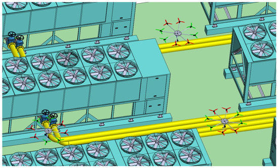
Figure 1.
Application of octorotor with manipulator arm in pipelines.
2.2. Conceptual Model of the Multirotor Vehicle
A conceptual model of an octorotor UAV with a manipulator arm is developed, and the arm is placed at the bottom of the center of mass of the vehicle managing three revolute joints (see Figure 2).
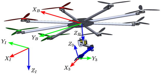
Figure 2.
Octorotor UAV and manipulator arm assembly.
Figure 3 shows the octorotor UAV, in which the rotors in red color represent the front of the vehicle and are on the positive X-axis. The rotors in green color represent the right side in the top view of the multirotor and lie on the positive Y-axis. Using the right-hand rule, the positive Z-axis is pointing downward.
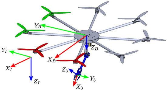
Figure 3.
Conceptual design of the octorotor UAV with manipulator arm.
2.3. Conceptual Model of the Manipulator Arm
Figure 4 depicts the manipulator arm with its three DOFs (degree of freedom) in a position that maintains the manipulator arm safely at the bottom of the aerial vehicle. This position is considered for simulation analysis in SimMechanics when the octorotor UAV takes off and the arm is retracted [24,25]. In the same figure, the coordinate frame from the Denavit–Hartenberg classical method is presented, where the coordinate frame is represented with the right-hand rule. The frame () is the base of the manipulator arm, the frames , , and are attached to the previous coordinate frames of the joint , , and , respectively. The coordinate frame is considered as the end-effector frame . The parameters , , and are the distances of each link described by Denavit–Hartenberg; additionally, , , and are the rotational positions of each joint, respectively. These variables are used to obtain a transformation matrix, and the circled numbers shown in Figure 4 are explained below:
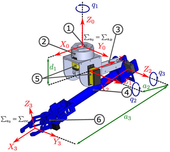
Figure 4.
Design and components of the manipulator arm.
- (1.)
- The base is attached to the multirotor vehicle; this base has no joint movement and is considered a fixed base;
- (2.)
- Link 1 is attached to the fixed base and performs the movement of the first joint. This link has three servomotors;
- (3.)
- Link 2 joins with link 1 and perforns the movement of the second joint;
- (4.)
- Link 3 is the last and is attached to the end-effector whose motion is caused by a servomotor attached between link 2 and link 3;
- (5.)
- Servomotors move the first two joints;
- (6.)
- The end-effector of the manipulation arm.
Figure 2 illustrates the assembly between the multirotor and manipulator arm. This integration is carried out at the center of mass of the UAV and the base of the manipulation arm.
2.4. Description of the Octorotor UAV
The octorotor UAV possesses eight rotors with a maximum angular velocity of 3700 (rpm) and a maximum load capacity of 2 (kg). The eight rotors are used together as the vehicle propulsion system providing a maximum load capacity of 16 (kg). For simulation purposes, carbon fiber is selected as a high-strength material, obtaining a total mass of 8 (kg). Acrylonitrile butadiene styrene (ABS) polymer is used to develop the manipulation arm as a light material with high resistance.
3. Mathematical Model of the Octorotor UAV with the Manipulator Arm
3.1. Kinematic Model
In this section, a kinematic model of the octorotor UAV with a manipulator arm is presented to calculate the position of the end-effector of the manipulator. The octorotor UAV has six DOFs to determine the Euclidean spaces, three DOFs are defined in the orientation or attitude motion, and the remaining three DOFs for the translation motions.
Remark 1.
The classical Denavit–Hartenberg convention is used as the robotic convention, North–West–Up. In this analysis, the aerodynamic NED convention North–East–Down is applied to the octorotor UAV and the North–West–Up convention for the manipulator arm is considered. Regarding the aerodynamic convention, the kinematic model of the manipulator arm adds a transformation matrix that converts the aerodynamic convention into the robotic convention.
Figure 5 describes the roll, pitch, and yaw motions of the octorotor UAV. The rotation matrix , where , is the attitude of the vehicle from the body frame () to the inertial frame (). is the translational position in . The rotation matrix maps the attitude of the UAV from through . A rotation sequence is used to determine the matrix.
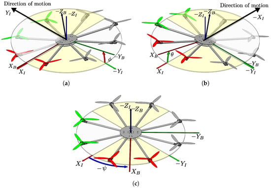
Figure 5.
Euler angles of the octorotor UAV attitude; (a) Roll angle (); (b) Pitch angle (); (c) Yaw angle ().
The matrix relation between the UAV and the manipulator arm is given by a homogeneous matrix that describes the attitude and translation of the systems [26]. The rotation matrix (1) and the position vector are considered to calculate the homogeneous matrix of the octorotor UAV.
The classical Denavit–Hartenberg convention is used to define the kinematic model of the manipulator arm position, .
where
3.2. Dynamic Model of the Octorotor UAV
The dynamic model of an octorotor UAV considers and , to describe the motion equations of the octorotor UAV, the Newton–Euler formulation is presented as follows [27,28]:
where vector represents the total thrust force on . The gravitational force is defined by , where m is the mass of the octorotor UAV, g is the gravity and vector is a unit vector representing the Z-axis.
The attitude is given by three Euler angles in . describes the attitude velocity in . represents the attitude velocities in (Euler rates). is the Euler matrix that describes the relationship between the attitude velocity in and the Euler rates. is the inertia matrix of the octorotor UAV. represents the applied moments to the octorotor UAV in , and it is also considered as the vector of the controller inputs for the attitude dynamics of the octorotor UAV.
3.2.1. Thrust Force
The thrust forces of the octorotor UAV allow to lift the vehicle during flight and this consist of a summation of all the thrust forces generated by the rotors .
The thrust force for each rotor is , where is the attitude velocity of a i-th rotor, and is the thrust coefficient of the propeller that depends on the aerodynamic characteristics of the propeller such as span, chord distribution, and twisting angle.
3.2.2. Moments
The moments acting on the vehicle are represented by Figure 5 and Figure 6 to describe the behavior in forces and moments of each rotor.
where and are the distance on the X and Y axes relative to 22.5 (deg) separations among each of the rotor axes, and d denotes the distance from center of mass to rotor axis. Since the distance p is close to the coordinate axis, it is disregarded. is the reaction moment of the i-th rotor, denotes the reactive moment coefficient of the rotor.
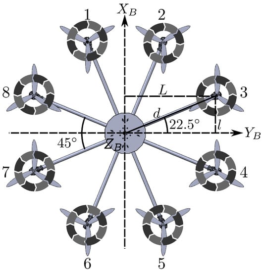
Figure 6.
Numbering and direction of rotation of the rotors in the Octorotor UAV.
Combining (9) and (10), an equation is defined with as the vector of total scalar thrust and moments, as the matrix of the aerodynamic coefficients, and as the vector of rotor speed with . The relation between the controller inputs and the attitude velocities of the rotors is described through an inverse equation using a pseudo-inverse method to obtain . The result is expressed as follows
where with .
Remark 2.
As the rotation of the eight propellers on the octorotor is balanced, gyroscopic moment will essentially be zero. The only case in which gyroscopic moments will not be zero is if there is a significant difference in the RPM of the eight motors and in the presence of a strong sideways cross-wind.
3.3. Octorotor UAV and Manipulator Arm System
The recursive Newton–Euler method calculates the positions and velocities of the translational and rotational motion of each link in terms of the previous link recursively. The classical Denavit–Hartenberg convention starts at the base of the manipulator arm and finishes at the end-effector. The base of the manipulator arm is defined by the link 0 when it is a fixed base, the positions and velocities of the translational and rotational motion are , , , and . In the case of the octorotor UAV with manipulator arm, the initial conditions of the manipulator arm base are the positions and velocities of the translational and attitude motion in the octorotor UAV , , and .
where and are rotational positions and velocities circulating through the i-th link. and propagate the translational positions and velocities along the link. Vector is a constant position vector of the origin of i-th link. Vector is the position vector of the center of mass of the i-th link. Finally, represents the translational velocities of the center of mass in the link. Once the forward calculations of the recursive Newton–Euler method are obtained, the backward calculations of the recursive Newton–Euler model are performed to obtain the forces and moments induced in each link starting in the end-effector and finishing in the base.
where and are inertia force and moment, respectively, presented at the center of mass in the i-th link. Furthermore, and are the reactive force and moment in the i-th link through the equilibrium in the center of mass, respectively. For the reactive force and moment of the previous link and , respectively, due to the recursive method, the computation begins in the payload force , and payload moment with j as the end-effector. In the absence of a payload, and . is the moment of the joint in the i-th link, and is the viscosity in the same link.
Equation (23) is replaced by the form where contains the inertia matrix of the links, represents centrifugal forces, Coriolis forces, and disturbances. is the vector containing the elements of the rotational moments of the manipulator arm, and is the vector containing the elements of the rotational accelerations of each joint. The direct mathematical model of the manipulator arm is presented as follows
Equations (21) and (22) at the base of the manipulator arm are considered to be the disturbance forces and moments for the octorotor UAV in , which are expressed as
where is the vector of the forces on that affect the dynamic of the octorotor UAV. is the vector of the moments that affect the dynamic of the octorotor UAV in , which is described in the following complete mathematical model of the octorotor UAV with manipulator arm:
Equations (27)–(29) and (33)–(35) are translational and attitude position equations in , while Equations (30)–(32) and (36)–(38) are velocity equations in .
4. Controller of the Octorotor UAV with Manipulator Arm
The controller system of the octorotor UAV with the manipulator arm is applied independently for the octorotor UAV and the manipulator arm. The octorotor UAV uses a two-layer saturated PID controller system. The first layer is the attitude, and the second layer is the navigation. The altitude and navigation controllers include the desired acceleration term.
4.1. Octorotor UAV Attitude Controller
For the formulation of the attitude controller problem of the first layer of the flight controller, the vector of the desired attitude is considered such that . This is represented by as the error vector of the attitude, which is defined as , , and , where , , and are the desired Euler angles. , , and are the measured roll, pitch, and yaw angles, respectively. The controller problem is strictly proposed from the controller vector , such that . A PID controller with a saturated moment is proposed for the attitude controller of the octorotor UAV. Considering that the state Equation (10), the external moments are rewritten to be expressed in terms of the attitude dynamics controller law, which is proposed as shown below
where , , , with being the proportional, derivative, and integral gains of the attitude controller layer for the roll, pitch, and yaw angles, respectively. A saturation function is added to the output of the attitude PID controller, as shown below.
where , , for each attitude controller corresponding to the desired Euler angles. The developed equations of the PID controller with saturation for attitude are expressed as
4.2. Octorotor UAV Altitude Controller
The altitude controller for the octorotor UAV is proposed as
in a closed-loop system with
where represents the translational position error of altitude, describes the error of the translational velocity, and defines the acceleration error. The variables with subscription d are the desired inputs. By considering the maximum and minimum thrust of each rotor, a saturation function is added to the output of the altitude PID controller, whose expression is shown as follows
The PID controller with thrust compensation is expressed as follows
where (rad) and (rad) are constrained to avoid a singularity. The thrust compensation is considered to be saturated by having a saturator in the PID controller of the altitude. Considering Equation (11), the controller laws corresponding to the rotors of the octorotor UAV are presented as follows
4.3. Octorotor UAV Navigation Controller
The inner layer of the attitude controller is integrated with the outer layer of the navigation flight controller of the octorotor UAV. In this sense, the desired variables of the attitude vector are computed through the navigation controller in the plane of , known as the navigation flight controller, where a virtual rotation matrix is used. To obtain a navigation controller for trajectory tracking in the plane, a PID controller with desired acceleration is proposed as
where and represent the position error, while and represent the desired position. Moreover, and define the errors in the translational velocity in the plane of . The variables and describe the desired translational velocities. Finally, and represent the desired accelerations. To limit the forces of the octorotor UAV with the navigation controller, a saturation function is used, which is connected to the output of the navigation PID controller, and it is shown as
where corresponds to the translation controller in the and directions in . The equations developed for the navigation controller in the plane are expressed as follows:
The proposed PID controller with desired acceleration term for navigation represents the external controller layer. The rotation matrix has the purpose of generating the desired angles through vector of the attitude controller inner layer; hence, the connection between the attitude and translation controllers is obtained using the following matrix expression
where
A complete scheme of the flight controller system of the octorotor UAV is shown in Figure 7; the diagram illustrates the connection of the internal attitude controller layer with the external navigation controller layer. Both layers of the controllers are interconnected to implement the complete flight controller system for trajectory tracking in three-dimensional space.
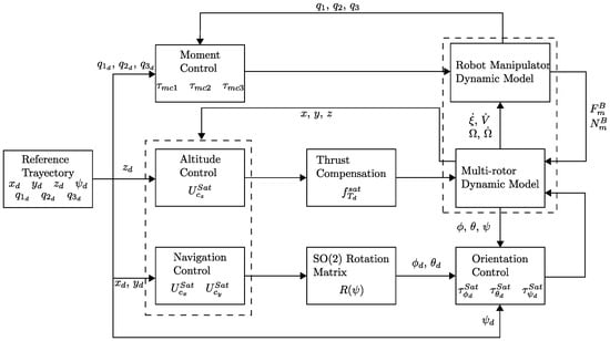
Figure 7.
Controller diagram of the octorotor UAV with manipulator arm.
4.4. Manipulator Arm Position Controller
The position controller, along with Equation (24), is considered to obtain the moments of the manipulator arm. It results in
where , , and describe the errors in the joint positions of each link of the manipulator arm, while , and are the variables of the desired position of each of the joints. Moreover, , , and define the errors in the velocities of each link in the manipulator arm joints. Figure 8 shows the feedback state scheme of the manipulator arm controlling the position of the joints.

Figure 8.
Diagram of the position controller system by calculating the moments applied to the manipulator arm.
4.5. Controller of the Octorotor UAV with Manipulator Arm in SimMechanics
The controller system implemented in Simulink-SimMechanics considers a mathematical form similar to that implemented in SimMechanics. The parameters of the gains are different from those used in Matlab since SimMechanics considers the inertia tensors, centers of masses, and the masses of each component designed in SolidWorks. Figure 9 illustrates the block diagram of SimMechanics.

Figure 9.
Diagram of the complete controller of octorotor UAV with manipulator arm.
5. Experimental Simulation of Flight Controller in SimMechanics
The proposed methodology for the design and implementation process of the octorotor UAV with a manipulator arm is shown in the following flowchart, see Figure 10. The characteristics of the UAV and the number of joints of the manipulator arm were defined. Once the UAV and manipulator arm systems were proposed, the CAD design of both systems was performed, defining the joining mechanisms. The kinematic and dynamic models of both systems were obtained and described according to the modeling requirements. Then, the CAD design was imported into SimMechanics, where the controllers were implemented in sequence to achieve system stability. The joint position controller of the manipulating arm is the first controller to perform the trajectory tracking of the joint positions which are stabilized. Consequently, the UAV orientation control stabilizes the desired angles, and the altitude of the aircraft is reached in order to obtain a stationary flight, and finally, the navigation control performs the trajectory tracking of the UAV.
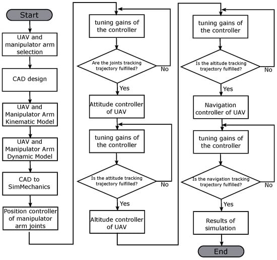
Figure 10.
Flowchart for the design and implementation process of the octorotor UAV with a manipulator arm.
The simulations were performed using a computer with Intel Core i7 10750 CPU @ 2.6 GHz, a 16 GB memory RAM, and a Nvidia GTX 1650 Ti GPU, which were indispensable to perform the simulations in MATLAB-Simulink 2019b with SimMechanics Toolbox. This simulation involves the octorotor UAV with manipulator arm performing a trajectory tracking of a helical shape that must reach a radius of three meters from the origin. In the first fifteen seconds, it is performed an increasing spiral, then it starts a helical trajectory toward the end of the simulation. At the same time, the octorotor UAV with the manipulator arm takes off to reach an altitude of three meters. The octorotor UAV trajectory tracking is performed with the retractable manipulator arm to avoid navigation and altitude controller issues. The simulation of trajectory tracking of the octorotor UAV with the manipulator arm is performed in SimMechanics.
The equations for the desired navigation trajectories are defined as follows:
where is the damping coefficient of the desired trajectory that determines the time to reach the desired radium of the circumference, (m) and (m) are the amplitude coefficients of the circumference at X and Y axes, respectively. The coefficient (s) is the time period of the desired trajectory, and t is the time variable. From the beginning of the simulation toward the period of two seconds, the manipulator arm is adjusted from the initial disabled position toward the retractable operational position. The equation indicates the beginning of trajectory tracking, where variable is the time period when the manipulator arm is secured. The parameters of the octorotor UAV with manipulator arm used in the simulations of SimMechanics are shown in the Table 1, Table 2, Table 3, Table 4 and Table 5.

Table 1.
Octorotor UAV physic parameters in SimMechanics.

Table 2.
Manipulator arm physic parameters in SimMechanics.

Table 3.
Octorotor UAV altitude and navigation controller gains.

Table 4.
Octorotor UAV attitude controller gains.

Table 5.
Manipulator arm moment controller gains.
Table 1 and Table 2 present the physic parameters in SimMechanics of the octorotor UAV and the manipulator arm, respectively, obtained through Solidworks and a datasheet of motors.
Table 3 presents the tuning of gain parameters for the PID navigation and altitude flight controller of the octorotor UAV, and Table 4 presents the tuning of gain parameters for the PID attitude flight controllers of the octorotor UAV. Table 5 shows the tuning of gain parameters for the PID joint moment controllers of the manipulator arm.
5.1. Response of the Joint Positions of the Manipulator Arm
Responses of joint positions of the manipulator arm are presented in Figure 11a–c. These figures show the behavior of the transient response of the three joints of the manipulator arm when the simulation begins. The joints perform the motion from the initial disabled position to the retractable operational position in the first two seconds. Then, the octorotor UAV takes off to perform the helical trajectory tracking with altitude ascending from two seconds toward thirty seconds and maintaining a constant position in altitude during the period from fifteen seconds to thirty seconds.
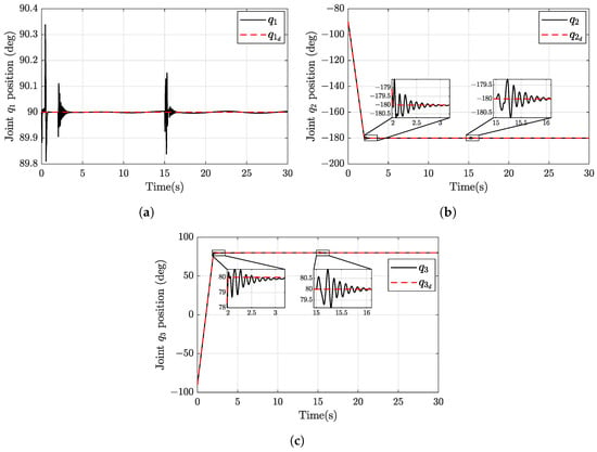
Figure 11.
Response joint positions of the manipulator arm; (a) Joint variable (black line) and desired variable (red dotted line); (b) Joint variable (black line) and desired variable (red dotted line); (c) Joint variable (black line) and desired variable (red dotted line).
Figure 11a shows joint with the actual value converging in desired value, and this position is considered to be maintained through the simulation. During the motion from the initial disabled position toward the retractable operational position of the manipulator arm, the octorotor UAV performs disturbances that affect minimally joint , when the octorotor UAV takes off to perform the trajectory tracking of helical shape with altitude ascending and then maintain a constant altitude position. The position of joint is affected by a disturbance produced due to the octorotor UAV maneuvering to perform the trajectory tracking of a helical shape in three-dimensional space.
Figure 11b illustrates the response position of joint that perform 90 (deg) counter-clockwise. This joint presents two disturbances that affect an approximate magnitude of 1 (deg) to the manipulator arm joint when the octorotor UAV takes off to perform the trajectory tracking of helical shape and when the octorotor UAV maintains a constant altitude position. For this reason, two close-up windows are presented inside Figure 11b to show the transient response of these disturbances.
Figure 11c presents the response of the position of joint of manipulator arm performing a motion of 180 (deg) clockwise. The disturbances are shown in close-up windows where the transient response is asymptotically vanishing to the desired value.
5.2. Attitude Flight Controller Response
Figure 12a–c show the behavior of Euler angles when the octorotor UAV with manipulator arm performs the trajectory tracking in plane, first with spiral shape and after, with a circular shape, while the altitude performs the tracking trajectory with a ramp shape.
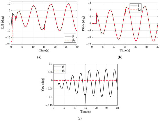
Figure 12.
Euler angles of the octorotor UAV: (a) Roll angle variable (black line) and desired variable (red dotted line); (b) Pitch angle variable (black line) and desired variable (red dotted line); (c) Yaw angle variable (black line) and desired variable (red dotted line).
Figure 12a presents the roll angle response, where it is possible to observe the roll signal controller (red dotted line) computed by the Equation (50) considering the trajectory tracking controller (Equation (49)) set to perform the navigation. Additionally, the roll angle is disturbed by the trajectory tracking of the altitude. When the trajectory of the circular shape reaches the radium of three meters, the roll angle is bounded by an amplitude peak of 11 (deg).
Figure 12b illustrates the pitch angle sinusoidal response, as in the case of roll angle, Equation (50) computes the pitch angle signal controller (red dotted line). During the motion from the initial disabled position toward the retractable operational position of the manipulator arm, joints and generate minimal disturbances in the pitch angle. When the octorotor UAV takes off to perform the helical trajectory tracking with ascending altitude at a constant velocity and when it maintains a constant altitude, these change velocity actions generate disturbances to joints and (see Figure 12b).
Figure 12c shows the yaw angle response, which is set point to 0 (deg) as the desired value (red dotted line) to maintain the nose of the octorotor UAV in the north direction. The yaw angle response (black line) presents a sinusoidal motion bounded by an amplitude peak of 0.1 (deg).
5.3. Altitude and Navigation Flight Responses
Figure 13a–c presents the behavior of the altitude and navigation in X and Y axes of the octorotor UAV with the manipulator arm.
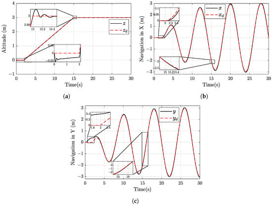
Figure 13.
Translational position responses: (a) Altitude variable z (black line), and desired variable (red dotted line); (b) X-axis variable x (black line), and desired variable (red dotted line); (c) Y-axis variable y (black line), and desired variable (red dotted line).
Figure 13a shows the altitude response (black line) with respect to the desired tracking (red dotted line). The octorotor UAV presents a failing effect at the beginning of the simulation due to the take-off base, and the octorotor UAV base is not achieving contact in the SimMechanics simulator. After the failing effect, the octorotor UAV with the manipulator arm recovers altitude because rotors are turned on from the beginning of the simulation. The octorotor UAV starts ascending for thirteen seconds, performing a constant velocity slope, then the ascending changes to a constant altitude, which generates an altitude disturbance caused by the manipulator arm due to this effect. The altitude of the octorotor UAV is maintained constant during the remaining simulation.
Figure 13b presents the navigation response in X-axis considering that the desired tracking is defined by Equation (53). The navigation in X is performed without disturbances. Due to the pitch angle response, the response converges with the desired tracking.
In the case of Figure 13c, in the beginning, the octorotor UAV in the Y-axis deviated from the initial position due to the manipulator arm performing the retractable position and the effect of failing in the altitude. The remaining navigation is performed without disturbances due to the roll angle response.
5.4. Speed Rotors, Disturbances, Forces, and Moments in the Octorotor UAV with Manipulator Arm
Figure 14a–d present the thrust force of each rotor in the octorotor UAV with the manipulator arm. The responses are compared between the rotors that are equal. The odd numbers are represented by the black line and the even numbers by the red dotted line. It can be seen that rotor 1 and rotor 2 (Figure 14a) are equal in force, and their counterparts are rotor 5 and rotor 6 (Figure 14c) with similar force and different behavior in the response due to disturbances. These four rotors increase the thrust force due to the manipulator arm located in the X-axis. The opposites of rotor 3 and rotor 4 (Figure 14b) are rotor 7 and rotor 8 (Figure 14d), and these rotors are decreasing the thrust force to stabilize the total thrust to flight the octorotor UAV. In the beginning, the octorotor UAV starts up rotors to avoid the effect of falling, as is shown in Figure 13a. After two seconds, the rotors increase the force to take off. At fifteen seconds, each rotor presents a disturbance due to the octorotor UAV altitude ascending changes to a constant altitude. The total force of 84 (N) is required to take off the full system. Each rotor is distributed to maintain the total force.
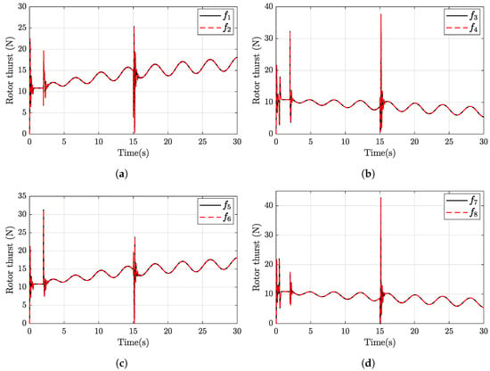
Figure 14.
Force of each pair of rotors: (a) Thrust force 1 (black line) and thrust force 2 (red dotted line); (b) Thrust force 3 (black line) and thrust force 4 (red dotted line); (c) Thrust force 5 (black line) and thrust force 6 (red dotted line); (d) Thrust force 7 (black line) and thrust force 8 (red dotted line).
Figure 15a–c presents the output forces in joint of the manipulator arm, and these forces are input disturbances to the center of mass of the octorotor UAV, where each force is computed by the Newton–Euler method. The Newton–Euler method starts calculating the translational forces produced in the end-effector. Since the end-effector does not grab an object, the end-effector lacks forces. Hence, the forces produced by joint are computed. Then, the forces generated by joint are calculated considering the forces produced by joint . Once the forces calculated in joint are obtained, the forces in joint are computed considering the forces in joint and joint . In conclusion, the forces in Figure 15 are propagated forces from the end-effector to joint , afterwards, joint to joint , and finally, joint to joint .
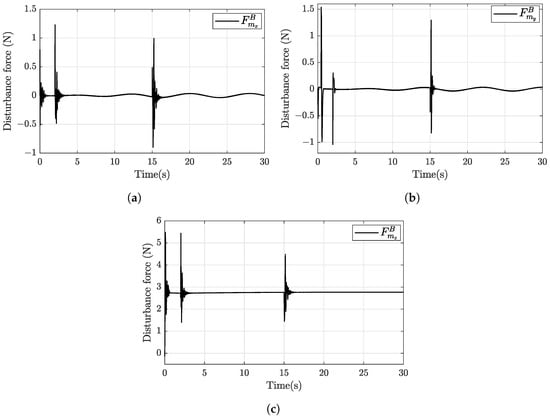
Figure 15.
Disturbance forces of the octorotor UAV: (a) Disturbance force in X-axis; (b) Disturbance force in Y-axis; (c) Disturbance force in Z-axis.
Figure 15a shows the force that disturbs the X-axis of the octorotor UAV fuselage. The X-axis is affected by joints and , considering the retractable position of the manipulator arm in Figure 4 with the location of the end-effector in the north position and the tracking trajectory of the octorotor UAV.
Figure 15b presents the force that disturbs the Y-axis of the octorotor UAV fuselage. Due to the retractable position of joints and can affect the Y-axis only if joint is affected by the tracking trajectory of the octorotor UAV; this can perform a direction change of the manipulator arm from X-axis to Y-axis.
Figure 15c illustrates the force that disturbs the altitude of the octorotor UAV fuselage. The joints and are the only ones that disturb the octorotor UAV. When the octorotor UAV takes off, this generates a jerk that affects joints and . These reactions generate forces in the Z-axis due to the control moments of joints and . The same action occurs when the octorotor UAV changes the response from ascending altitude to constant altitude.
In the case of the forces generated by the manipulator arm that affect the UAV octorotor, the moments that disturb the octorotor UAV are computed by the Newton–Euler method that propagates the accumulated moments from end-effect toward joint .
Figure 16a illustrates the roll moment disturbed by the altitude tracking of the octorotor UAV. The octorotor UAV generates sinusoidal movements over the X-axis due to the inertial moment of the octorotor UAV and the mass of the manipulator arm.

Figure 16.
Disturbance moments of the octorotor UAV: (a) Disturbance roll moment; (b) Disturbance pitch moment; (c) Disturbance yaw moment.
Figure 16b shows the moment that disturbs the pitch moment of the octorotor UAV. The pitch moment is affected by the sinusoidal of the octorotor UAV fuselage due to control moment responses of joints and .
Figure 16c presents the yaw moment that disturbs the octorotor UAV. Yaw moment is affected by the response of joint and the trajectory tracking of the octorotor UAV. Due to the yaw position being bounded in the amplitude of 0.1 (deg) (see Figure 12c), this disturbance is minimal for the octorotor UAV.
Figure 17a–c presents the reactive responses that control the moment of each joint of the manipulator arm. In the first two seconds, the control moment of each joint in the manipulator arm presents responses due to the tracking position from the initial position to the retractable position. When the octorotor UAV starts ascending trajectory, the control moment applied to joints presents a reactive response due to the octorotor UAV ascending trajectory. Then, at fifteen seconds, the octorotor UAV changes from ascending trajectory to a constant altitude, and the control moment applied to joints performs a second reactive response.
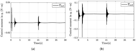
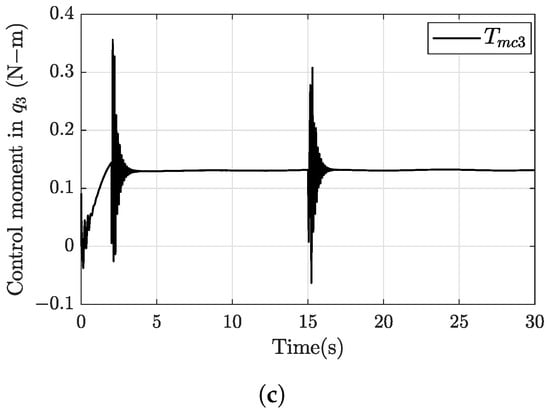
Figure 17.
Control moment of each joint in manipulator arm: (a) Joint ; (b) Joint ; (c) Joint .
Figure 17a illustrates the reactive response of control moment applied to joint . The control moment of joint presents a lower magnitude in the time periods where the disturbances occur than the control moments of joints and , which is because joint is located closer to the center of mass of the UAV octorotor.
Figure 17b shows the reactive response of control moment applied to joint . The control moment of joint performs a damped sinusoidal response when joint tracks the desired position. The control moment has an initial negative peak response when the octorotor UAV starts ascending trajectory.
Figure 17c presents the reactive response of control moment applied to joint . When the simulation starts, the joint performs the tracking position from the initial position to the retractable position. The control moment presents a positive peak response due to the desired tracking altitude of the octorotor UAV in the period of two seconds in which the take-off was performed.
5.5. Simulation with a Disturbance
In the simulation, a wind gust disturbance on the Y-axis was added, which is represented by a train of Gaussian pulses on small time lapses. The wind gust disturbance consists of two pulses with 0.5 (m/s) amplitude, and one pulse of 1 (m/s) amplitude. The three pulses have an approximate duration of 2 (s) so that the wind gust occurs in a total time of 10 (s), see Figure 18.
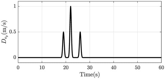
Figure 18.
Disturbance of Wing gust.
Figure 19 shows the top view where it is observed that the wind gust produces a deviation in the Y-axis of the trajectory with respect to the desired trajectory, in the time interval between 17 and 27 (s). From second 27, the aircraft returns, following the desired trajectory. The vehicle in the X- and Z-axes tracks the desired trajectory without presenting a deviation. The saturated PID control of the vehicle roll moment acts on the rejection of disturbances to conduct the trajectory tracking of the desired angle. On the other hand, the saturated PID control of the pitch angle produces the decoupling of the roll angle to produce a rejection of disturbances. However, in the case of the saturated PID control for the yaw angle, according to the Figure 20, for the link 1 joint (), it is observed that a coupling occurs in the yaw disturbance. In effect, the yaw angle control rejects the coupled disturbances maintaining a stable yaw system. Finally, the joints and of the manipulator arm present an almost imperceptible disturbance with a small magnitude so that it does not affect the trajectory of the vehicle.
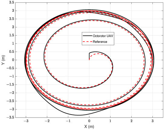
Figure 19.
Trajectory response with disturbance.
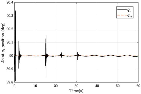
Figure 20.
Response joint position of the manipulator arm with disturbance.
5.6. 3D Navigation Flight Controller
Figure 21 illustrates a sequence of motions with frames in the same scenery of the 3D navigation of the octorotor UAV with the manipulator arm that is implemented in SimMechanics. Figure 22 represents the trajectory of the octorotor UAV with the manipulator arm concerning Figure 21. The black line represents the trajectory tracking of the octorotor UAV, the blue line is the trajectory tracking of the end-effector position in the manipulator arm, and the red dotted line represents the desired trajectory tracking. The octorotor UAV with the manipulator arm response is presented by a timeline of sixty seconds and a maximum altitude of five meters.
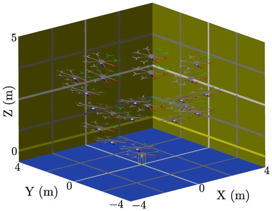
Figure 21.
Sequence of motions of the octorotor UAV with the manipulator arm in SimMechanics simulation.
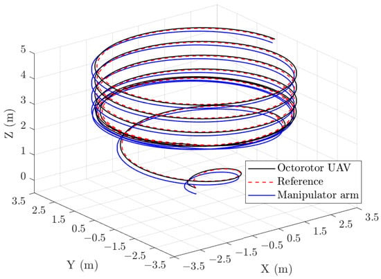
Figure 22.
Trajectory tracking of the octorotor UAV with manipulator arm in SimMechanics.
A virtual simulation was performed and is available on the following link https://youtu.be/WGZ4zA7avsw (accessed on 15 July 2022).
6. Conclusions
The octorotor UAV with manipulator arm model was designed and implemented in Simulink-SimMechanics, which allows us to evaluate and analyze the coupling of forces and moments performed by the manipulator arm inducing disturbance effects on the navigation tracking trajectory of the octorotor UAV. In this sense, it was observed that the translational and orientation movements of the octorotor UAV induce disturbances that affect the joint position control of the manipulator arm. Furthermore, the forces and moments produced by the joint motions of the manipulator arm also induce disturbances that affect the behavior of the dynamics during the flight of the octorotor UAV. For the purpose of navigation, the kinematics equation was obtained using the classical Denavit–Hartenberg convention, and the Newton–Euler approach was used to obtain the dynamic equations. Then, the closed-loop system was simulated using SimMechanics running in the Simulink environment. Our design was validated in numerical simulation, obtaining promising results which show a complete performance of the octorotor UAV with a manipulator arm in trajectory tracking.
For future works, the manipulator arm will be developed and integrated into the experimental platform in order to perform real-time tasks. The platforms will be equipped with high-performance sensors in order to execute real-time applications.
Author Contributions
E.J.O.-V. proposed the design and modeling of the octorotor UAV with a manipulator arm and wrote the first draft. P.A.T.-B. worked on the mathematical models and conducted the simulations. E.G.R.-R. worked on the simulation and wrote the first draft. V.S. proposed the modeling and controllers of the manipulator arm. L.A.R.-O. worked on the virtual simulation. O.G.-S. improved the manuscript and supervised the overall project. All the authors discussed the proposed approach, results, reviewed and approved the paper. All authors have read and agreed to the published version of the manuscript.
Funding
This research work is supported by the Office of Naval Research Global through the award number N62909-20-1-2030.
Institutional Review Board Statement
Not applicable.
Informed Consent Statement
Not applicable.
Data Availability Statement
All research data supporting this study are included in the manuscript.
Acknowledgments
The authors would like to thank the Autonomous University of Nuevo Leon (CIIIA-FIME-UANL) and the Technological Institute of La Laguna-TecNM.
Conflicts of Interest
The authors declare no conflict of interest.
References
- Ebrahimy, A.; Zarafshan, P.; Hassan-Beygi, S.R.; Dehghani, M.; Hashemy, S.E. Design and Analysis of a Solar Linear Move Irrigation System. In Proceedings of the 2018 6th RSI International Conference on Robotics and Mechatronics (IcRoM), Tehran, Iran, 23–25 October 2018; pp. 382–387. [Google Scholar]
- Hajiahmadi, F.; Dehghani, M.; Zarafshan, P.; Moosavian, S.A.A.; Hassan-Beygi, S.R. Trajectory Control of a Robotic Carrier for Solar Power Plant Cleaning System. In Proceedings of the 2019 7th International Conference on Robotics and Mechatronics (ICRoM), Tehran, Iran, 20–21 November 2019; pp. 463–468. [Google Scholar]
- Hajiahmadi, F.; Zarafshan, P.; Dehghani, M.; Moosavian, S.A. A.; Hassan-Beygi, S.R. Dynamics Modeling and Position Control of a Robotic Carrier for Solar Panel Cleaning System. In Proceedings of the 2019 7th International Conference on Robotics and Mechatronics (ICRoM), Tehran, Iran, 20–21 November 2019; pp. 613–618. [Google Scholar]
- Cai, G.; Dias, J.; Seneviratne, L. A survey of small-scale unmanned aerial vehicles: Recent advances and future development trends. Unmanned Syst. 2014, 2, 175–199. [Google Scholar] [CrossRef]
- Freddi, A.; Lanzon, A.; Longhi, S. A feedback linearization approach to fault tolerance in quadrotor vehicles. IFAC Proc. Vol. 2011, 44, 5413–5418. [Google Scholar] [CrossRef]
- Ghadiok, V.; Goldin, J.; Ren, W. On the design and development of attitude stabilization, vision-based navigation, and aerial gripping for a low-cost quadrotor. Auton. Robot. 2012, 33, 41–68. [Google Scholar] [CrossRef]
- Doyle, C.E.; Bird, J.J.; Isom, T.A.; Kallman, J.C.; Bareiss, D.F.; Dunlop, D.J.; King, R.J.; Abbott, J.J. & Minor, M.A. An avian-inspired passive mechanism for quadrotor perching. IEEE/ASME Trans. Mechatronics 2013, 18, 506–517. [Google Scholar]
- Suarez, A.; Heredia, G.; Ollero, A. Lightweight compliant arm for aerial manipulation. In Proceedings of the 2015 IEEE/RSJ International Conference on Intelligent Robots and Systems (IROS), Hamburg, Germany, 28 September–3 October 2015; pp. 1627–1632. [Google Scholar]
- Danko, T.W.; Chaney, K.P.; Oh, P.Y. A parallel manipulator for mobile manipulating UAVs. In Proceedings of the 2015 IEEE international conference on technologies for practical robot applications (TePRA), Woburn, MA, USA, 11–12 May 2015; pp. 1–6. [Google Scholar]
- Mellinger, D.; Lindsey, Q.; Shomin, M.; Kumar, V. Design, modeling, estimation and control for aerial grasping and manipulation. In Proceedings of the 2011 IEEE/RSJ International Conference on Intelligent Robots and Systems, San Francisco, CA, USA, 25–30 September 2011; pp. 2668–2673. [Google Scholar]
- Korpela, C.M.; Danko, T.W.; Oh, P.Y. MM-UAV: Mobile manipulating unmanned aerial vehicle. J. Intell. Robot. Syst. 2012, 65, 93–101. [Google Scholar] [CrossRef]
- Cano, R.; Pérez, C.; Pruano, F.; Ollero, A.; Heredia, G. Mechanical design of a 6-DOF aerial manipulator for assembling bar structures using UAVs. In Proceedings of the 2nd RED-UAS 2013 Workshop on Research, Education and Development of Unmanned Aerial Systems, Compiegne, France, 20–22 November 2013; Volume 218. [Google Scholar]
- Bernard, M.; Kondak, K.; Maza, I.; Ollero, A. Autonomous transportation and deployment with aerial robots for search and rescue missions. J. Field Robot. 2011, 28, 914–931. [Google Scholar] [CrossRef]
- Michael, N.; Fink, J.; Kumar, V. Cooperative manipulation and transportation with aerial robots. Auton. Robot. 2011, 30, 73–86. [Google Scholar] [CrossRef]
- Hunt, G.; Mitzalis, F.; Alhinai, T.; Hooper, P.A.; Kovac, M. 3D printing with flying robots. In Proceedings of the 2014 IEEE International Conference on Robotics and Automation (ICRA), Hong Kong, China, 31 May–7 June 2014; pp. 4493–4499. [Google Scholar]
- Coulombe, C.; Saussié, D.; Achiche, S. Modeling and gain-scheduled control of an aerial manipulator. Int. J. Dyn. Control. 2022, 10, 217–229. [Google Scholar] [CrossRef]
- Ding, Y.; Wang, Y.; Chen, B. A practical time-delay control scheme for aerial manipulators. Proc. Inst. Mech. Eng. Part I J. Syst. Control. Eng. 2021, 235, 371–388. [Google Scholar] [CrossRef]
- Zhou, Z.; Wei, H.; Liu, X.; Lu, L.; Wang, Y.; Lv, Y. Modeling, Simulation and Verification of Quadrotor UAV. In Proceedings of the 2020 2nd International Conference on Robotics, Intelligent Control and Artificial Intelligence, Shanghai, China, 17–19 October 2020; pp. 44–48. [Google Scholar]
- Tandel, A.; Deshpande, A.R.; Deshmukh, S.P.; Jagtap, K.R. Modeling, analysis and PID controller implementation on double wishbone suspension using SimMechanics and Simulink. Procedia Eng. 2014, 97, 1274–1281. [Google Scholar] [CrossRef]
- Mariappan, S.M.; Veerabathiran, A. Modelling and simulation of multi spindle drilling redundant SCARA robot using SolidWorks and MATLAB/SimMechanics. Rev. Fac. Ing. Univ. Antioq. 2016, 63–72. [Google Scholar] [CrossRef]
- Kang, H.J.; Ro, Y.S. Robot manipulator modeling in Matlab-SimMechanics with PD control and online gravity compensation. In Proceedings of the International Forum on Strategic Technology 2010, Ulsan, Republic of Korea, 13–15 October 2010; pp. 446–449. [Google Scholar]
- Kathpal, A.; Singla, A. SimMechanics™ based modeling, simulation and real-time control of Rotary Inverted Pendulum. In Proceedings of the 2017 11th International Conference on Intelligent Systems and Control (ISCO), Coimbatore, India, 5–6 January 2017; pp. 166–172. [Google Scholar]
- Shaoqiang, Y.; Zhong, L.; Xingshan, L. Modeling and simulation of robot based on Matlab/SimMechanics. In Proceedings of the 2008 27th Chinese Control Conference, Kunming, China, 16–18 July 2008; pp. 161–165. [Google Scholar]
- Jatsun, S.; Lushnikov, B.; Emelyanova, O.; Leon, A.S. M. Synthesis of simmechanics model of quadcopter using solidworks CAD translator function. In Proceedings of the 15th International Conference on Electromechanics and Robotics “Zavalishin’s Readings”, ER(ZR) 2020, Ufa, Russia, 15–18 April 2020; pp. 125–137. [Google Scholar]
- Udai, A.D.; Rajeevlochana, C.G.; Saha, S.K. Dynamic simulation of a KUKA KR5 industrial robot using MATLAB SimMechanics. In Proceedings of the 15th National Conference on Machines and Mechanisms, Chennai, India, 30 November–2 December 2011; Volume 96, pp. 1–8. [Google Scholar]
- Bajd, T.; Mihelj, M.; Lenarčič, J.; Stanovnik, A.; Munih, M. Robotics; Springer Science & Business Media: Heidelberg, Germany, 2010; Volume 43. [Google Scholar]
- Stengel, R.F. Flight Dynamics; Princeton University Press: Princeton, NJ, USA, 2004. [Google Scholar]
- Stevens, B.L.; Lewis, F.L. Aircraft Control and Simulation; John Wiley and Sons: Hoboken, NJ, USA, 1992. [Google Scholar]
Disclaimer/Publisher’s Note: The statements, opinions and data contained in all publications are solely those of the individual author(s) and contributor(s) and not of MDPI and/or the editor(s). MDPI and/or the editor(s) disclaim responsibility for any injury to people or property resulting from any ideas, methods, instructions or products referred to in the content. |
© 2023 by the authors. Licensee MDPI, Basel, Switzerland. This article is an open access article distributed under the terms and conditions of the Creative Commons Attribution (CC BY) license (https://creativecommons.org/licenses/by/4.0/).