1. Introduction
With the continuous development of information technology, the space range of information service has expanded from well-developed terrestrial communication to air-to-ground (A2G) communication and satellite communication. Unmanned aerial vehicles (UAVs) have become a very attractive research topic in A2G communication and satellite communication owing to their various advantages, such as mobile flexibility, small size, and low cost [
1,
2,
3]. UAVs can have significant influence in agriculture, aerial surveys, and public rescue, and can even be used as a satellite communication relay to expand coverage and ensure communication quality. The drone network has also been developed comprehensively, such as through a novel offset feedback fractionally spaced equalization architecture, the design of drone-aided IoT networking, and a high-mobility support system for NTN connectivity [
4,
5,
6]. In terms of profit, a UAV can be used as a cost-effective air platform for A2G communications. However, one major feature of A2G communication is its dynamic mobility. For example, in common UAV scenarios, speeds of 161 km/h may be reached. In certain scenarios, such as when using military UAVs and future aircraft, the flight speed can reach even more than 500 km/h, at which speeds they experience large path loss and serious Doppler spread, which may hinder the quality of the A2G link [
7,
8]. Therefore, it is very important to study robust A2G wireless links for high-speed A2G communication.
OFDM technology is widely used in terrestrial communication, such as 4G, because of the advantage of orthogonal subcarriers. However, with the increase in Doppler spread, orthogonality is no longer maintained [
9]. Orthogonal time–frequency space (OTFS) modulation, a novel 2D modulation in the delay–Doppler (DD) domain, has been proposed to solve this problem; this allows the time and frequency diversity to be fully exploited by the 2D convolution between the modulation symbols and the effective channel in the DD domain [
10]. The effective channel in the DD domain achieves near-constant channel gain, which is quite different from time-varying channels in the time–frequency (TF) domain. At the same time, the channel is sparse because there are limited reflectors in the propagation path, which is beneficial to the design of the receiver [
11,
12].
According to the characteristics of the channel, many studies on signal detection have been carried out, such as on LMMSE, MP, MRC, and Bayes schemes [
13,
14,
15,
16]. In practical signal detection, the correct channel state information is also indispensable. Some effective approaches have also been developed, such as the classical threshold-based method, orthogonal matching tracking (OMP), sparse Bayes, and our previous work on a DNN-based scheme [
17,
18,
19,
20]. Additionally, some novel structure designs for OTFS have been proposed. Explicitly, in order to convey additional information in high-mobility scenarios, a new OTFS scheme with index modulation (OTFS-IM) is proposed in [
21], which explores a new dimension. Compared with the conventional OTFS modulation, OTFS-IM modulation can convey additional index information by combining active and silent DD domain symbols to improve spectral efficiency. Moreover, the transmitted data in DD domain are sparser, which effectively reduces the interference and also leads to a significant gain in bit error rate (BER) performance. The authors in [
22] explored the potential of OTFS-IM modulation and proposed an OTFS-IM with dual-mode modulation (OTFS-DM-IM), where the symbols in the DD domain are modulated by two constellation matrices to transmit more additional index bits, thus achieving a higher transmission rate. To increase the spectral efficiency of the existing OTFS-IM schemes, there is a new transmission scheme called OTFS-I/Q-IM [
23]. By extending the grid index of OTFS systems to in-phase and quadrature dimensions, this new scheme has two index dimensions and
L-ary PAM constellation symbols to transmit information. However, most of the existing methods obtain a better detection performance by increasing the index dimensions, which increases the number of modulation steps and makes the transmitter design more complex.
Another major feature of A2G communication in the UAV scenario is the limited energy of the UAV. Due to its small size, there are restrictions on payload and energy storage, which prevent it from performing remote operations over a long time [
24]. Therefore, low-power communication research is still of great significance for an A2G network. Currently, most of the work on OTFS and OTFS-IM systems is based on two-dimensional modulation, such as quadrature amplitude modulation (QAM). In fact, it is possible to utilize multiple resource symbols jointly to increase the modulation dimension. For example, we can achieve four dimensions by combining two symbols together. According to the classical detection theory, a higher modulation dimension could have a larger minimum Euclidean distance between constellation points if it is elegantly designed, which confers better anti-interference and detection performance [
25].
Given that the traditional OTFS-IM modulation could be improved and there are resource constraints on the UAV communication, it is critically important to design an optimal and practical OTFS-IM system for A2G communication. To this end, this paper creatively introduces four-dimensional spherical code into the OTFS-IM system, denoted as OTFS-IM4, where the spherical code is similar to the sphere packing problem [
26]. Correspondingly, the conventional two-dimensional modulation is denoted as OTFS-IM2. The main contributions of this paper are as follows:
To enhance the endurance of UAVs, an OTFS-IM system based on four-dimensional spherical code is proposed in this paper, which allows the OTFS-IM system to have good signal detection performance under low signal-to-noise ratio. The design and implementation of this system are elaborately described in the paper;
In addition, this paper analyzes the proposed system, both analytically and numerically, to derive the approximate value of the bit error rate (BER) and the upper bound of the peak-to-average-power ratio (PAPR), which has general guiding significance.
The rest of the paper is organized as follows:
Section 2 introduces the basic model of the OTFS-IM system with the high-dimensional spherical code.
Section 3 analyzes the performance of BER and PAPR in our proposed scheme.
Section 4 verifies the effectiveness of the high-dimensional modulation and the practical significance of the theoretical analysis in
Section 3. Finally,
Section 5 concludes the paper.
2. System Model
We consider an OTFS-IM frame with
subcarriers and
symbols. The subcarrier spacing and symbol duration are denoted as
and
, respectively. Therefore, an OTFS-IM frame with duration
and bandwidth
could be treated as an
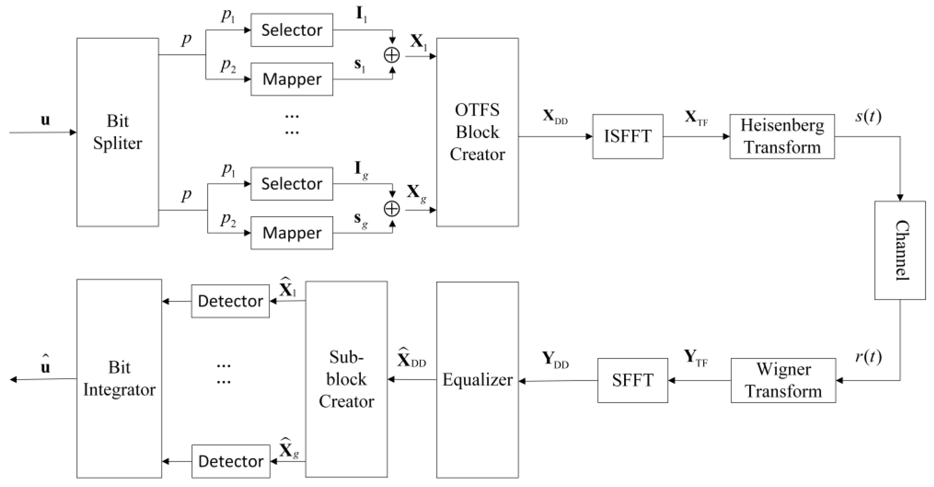
grid in the DD domain. The block diagram of the OTFS-IM system with four-dimensional spherical code modulation is shown in
Figure 1. It is assumed that there are
symbols and
active symbols in a sub-block, where “symbols” here represents bins in the DD grid. Then, an OTFS-IM4 frame can be divided into
groups. The transmitted bit set
is evenly divided into
groups, where each sub-block transmits
bits. Specifically, the
bits and
bits are used for index selection and constellation mapping, respectively. Since all OTFS-IM4 sub-blocks are independent of each other, the
-th sub-block is taken as an example for description.
As mentioned before, increasing the dimensions enables a larger Euclidean distance between constellation points when the design is elegant. We mainly consider four-dimensional spherical code modulation as constellation mapping in this paper. To begin with,
represents the surface of the unit sphere in
L-dimensional space:
where
is a point on
, and
is the amplitude of the
l-th dimension. Taking
points of the surface as the modulation constellation alphabet
, the spherical code can be expressed as
, where
represents the angle between two point vectors. According to the Law of Cosines, the minimum Euclidean distance between two points of
is
when
reaches the maximum attainable value. Sloane, Hardin, and Smith have given the arrangements in three, four, and five dimensions with
= 4, 5, ···, 130 [
27]. For the four-dimensional spherical code, we choose
,
, and
, which maximizes the minimum distance
between constellation points [
27]. Among the 16 points generated by spherical code
, each constellation is a four-dimensional vector representing four information bits and is listed as a column of the constellation matrix
:
Because the four-dimensional constellation point of is a four-dimensional vector, two two-dimensional symbols will be used jointly to carry a four-dimensional symbol in the OTFS-IM4 system. is transmitted by two-dimensional symbols and . These two symbols are denoted as . Therefore, the number of active symbols should be a multiple of 2, which means there are four-dimensional symbols in a sub-block. Consequently, the number of constellation mapping bits is .
To facilitate signal detection, we consider
as continuous, and non-overlap symbols are selected together as the active symbols among
symbols in a sub-block. The index set can then be represented as
, where
comes from the set
and is an integer in general. For example, the index selection lookup table when
is depicted in
Table 1. For the
-th sub-block, the index selection is a subset of the index set
, denoted as
. The number of index selection bits is
. So far, the total bits in a sub-block are as follows:
so the spectral efficiency is
. Finally, the symbols of the
-th sub-block can be written as:
For the subsequent OTFS modulation, the modulated sub-blocks are organized into the OTFS frame
along the Doppler axis through the frame creator. The signal in the TF domain is obtained from
via Inverse Symplectic Fast Fourier Transform (ISSFT). Then, it is converted to the time domain expressed as
by Heisenberg transform and shaping pulse:
where
are the transmitted shaping pulse matrix,
num-point normalized Fourier transform matrix, and Hermitian transformation, respectively. Thus, the transmitted signal
in the time domain can be expressed as:
where
is the column-wise operation,
is the Kronecker product, and
is the column-wise vector of
.
The signal
is transmitted over the time-varying channel, and then the received signal
can be expressed as:
where
is the additive Gaussian white noise with mean 0 and variance
, and
is the channel matrix in the time domain. The expression of
is as follows:
where
P is the number of propagation paths,
is the channel gain of the
i-th path,
is the permutation matrix (forward cyclic shift) reflecting the delay, and
is the diagonal matrix reflecting the Doppler.
The received signal
can also be rewritten as an
matrix
by the inverse column-wise operation. In order to obtain the received signal
in the DD domain, the receiver performs in reverse compared with the transmitter, including in its shaping pulse, Wigner transform, Symplectic Fast Fourier Transform (SSFT), and column-wise operation:
where
represent the matrix form of the received signal in DD domain and the received shaping pulse matrix, respectively.
Combined with Equations (5), (6) and (9), the input–output relationship in the DD domain can be expressed as:
where
.
It is assumed that the channel state information is well known at the receiver. After the MMSE equalization for
, the estimated signal
in the DD domain is obtained. The MMSE equalization used in this paper is a basic MMSE approach that can be expressed as follows [
9]:
where
is the column-wise vector of
,
is the column-wise vector of
, and
represents the variance in noise in the DD domain. The noise vectors in the time domain and the DD domain have the same statistical properties since they are related by unitary transformations. Then, the ML detector is used to demodulate the signals, sub-block by sub-block. The index information and the modulated symbols information in the
-th sub-block are detected as:
where
is the potential cases of sub-blocks. For each sub-block, there are
possible options for the modulated symbols, and there are
different situations for index selection. Therefore, the number of potential cases for a sub-block is
, which is also the complexity of detecting a sub-block using the ML detection algorithm.
4. Simulation Results
In
Section 2 and
Section 3, the general model of the proposed system and the mathematical expression of performance have been discussed in detail. Then, in this section, we simulate and examine the reliability and robustness of the proposed scheme and compare it with the conventional OTFS-IM scheme [
18]. Additionally, the simulation results and mathematical analysis are also compared to verify the correctness of the derivation.
As mentioned before, we focus on the four-dimensional spherical code
, whose constellation matrix
is normalized, and two two-dimensional symbols convey one four-dimensional symbol, meaning that the total energy of a sub-block is
. However, in the traditional OTFS-IM system, the total energy of
active symbols in a sub-block is
. In order to maintain the same energy, the actual amplitude of each constellation point of
should be
, which changes the constellation matrix as
and the minimum distance as
. An example of the index selection relationship is illustrated in
Table 1, where a sub-block transmits a four-dimensional constellation point with the total bits
. Therefore, the bit signal-to-noise ratio is
. Furthermore, we consider an OTFS frame with
and
. The operating carrier frequency is
, and the subcarrier spacing is
. As the number of paths in A2G communication is generally small, we model the channel as a two-path model, with reference to the model of the NTN-TDL series of the 3GPP standard [
30]. The maximum speed of the UAV is set to 500 km/h, and the maximum delay is about 4 us.
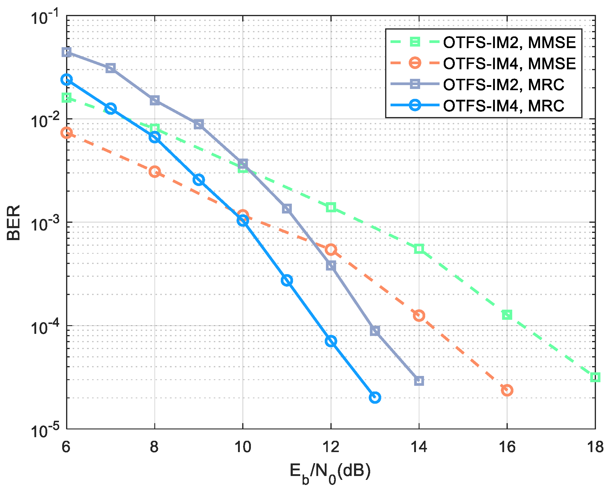
In
Figure 2, we compare the BER performance of our proposed OTFS-IM4 scheme with that of the traditional OTFS-IM2 scheme. According to reference [
17], the number of transmitted bits in a sub-block of the OTFS-IM2 system is
. For fairness, sub-block parameters
and BPSK modulation are selected in the traditional two-dimensional modulation to transmit the same number of bits as the four-dimensional modulation. At this time, the lookup table in the OTFS-IM2 system has only four options to choose, which is the same as in the proposed scheme, and the spectral efficiencies are all
. As discussed in
Section 2, MMSE equalization and ML detection are performed successively for signal detection. It is obvious that the four-dimensional modulation has almost 2 dB gain compared with the two-dimensional modulation, which is consistent with the classic detection theory. Thus, the bit signal-to-noise ratio can be reduced under the acceptable BER, which plays an important role in saving the transmitting power and prolonging the flight time of the UAV. Since MMSE equalization needs to calculate the matrix inverse, the complexity is
, which exponentially increases as the OTFS frame size grows. In contrast, the complexity of the MRC algorithm is
[
15], where
represents the number of distinct delay paths among
P propagation paths, and
denotes the number of iterations for the MRC algorithm. Therefore, the complexity of the MRC algorithm is lower than that of the MMSE algorithm. In addition, it can easily be used in the index modulation system for equalization by converting hard decisions into soft decisions. It can be seen that the performance of MRC is gradually better than MMSE when the
exceeds 10 dB. In particular, MRC equalization performs better than MMSE equalization, with more than 2 dB gain when the BER is
. However, there is zero padding in MRC equalization, which leads to a decrease in spectral efficiency [
15]. In summary, there is a trade-off between application and performance. Therefore, an appropriate equalization method should be selected based on application scenarios in reality.
Figure 3 presents the generalization of the OTFS-IM4 system at different speeds. To thoroughly investigate the effects of different Dopplers, we have taken into account both small UAV scenarios and higher-speed scenarios, such as those with military UAVs and future aircraft. Therefore, the selected flight speeds in simulation are 100 km/h and 500 km/h. As the speed increases, the BER performance behaves similarly, except there is a slight difference that proves the effectiveness of the OTFS-IM4 at different moving speeds. This means that under the same BER threshold and energy consumption, when transmitting signals are in the same communication range, a UAV in the OTFS-IM4 system can have a higher moving speed or have a larger communication range at the same speed.
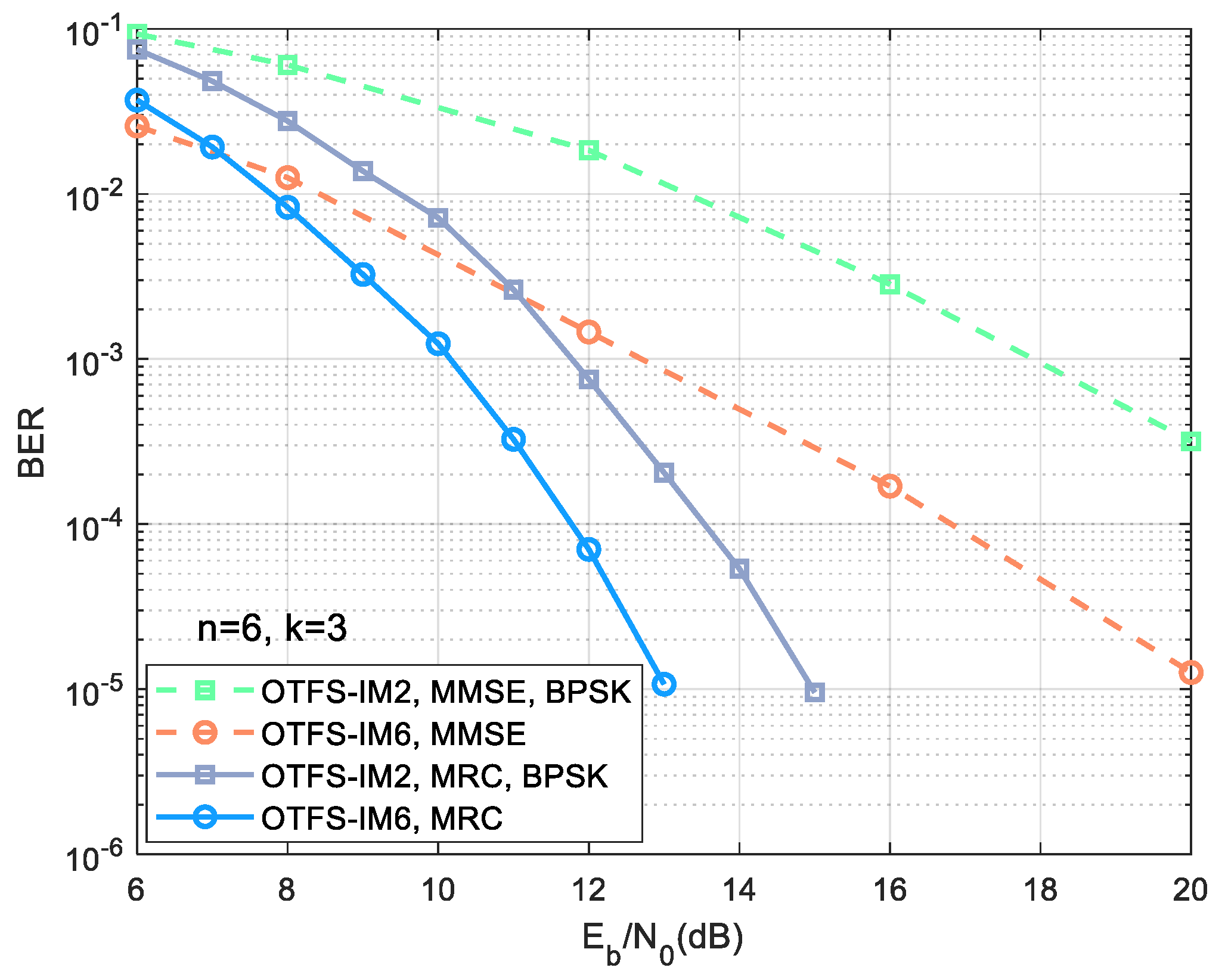
Figure 4 simulates the performance of an OTFS-IM system with a six-dimensional spherical code (denoted as OTFS-IM6) to analyze the robustness of the proposed system. According to the system model in
Section 2, when the 64-point spherical code is used for six-dimensional modulation, the sub-block parameters are selected as
and
. Since sub-blocks are organized along the Doppler axis, we choose the OTFS frame with
and
to ensure that the sub-block will not be separated. Other parameters remain the same as in
Figure 2. As can be seen from
Figure 4, the performance of MMSE equalization is about 4.5 dB lower than that of MRC when
. Additionally, in the MRC equalization results, the six-dimensional modulation has a gain of more than 1.5 dB compared with the two-dimensional modulation. It is 0.5 dB higher than the gain between the OTFS-IM4 system and the OTFS-IM2 system in
Figure 2. The conclusion drawn is that the higher the dimension, the better the performance. However, the detection is sub-block by sub-block in the proposed scheme using the ML method. The complexity of detecting a sub-block is
in the six-dimensional modulation and then the complexity of detecting an OTFS frame will be
. Therefore, the higher the dimension and the higher the number of constellation points, the higher the complexity. In this paper, four-dimensional modulation is chosen to take into account both performance and detection complexity.
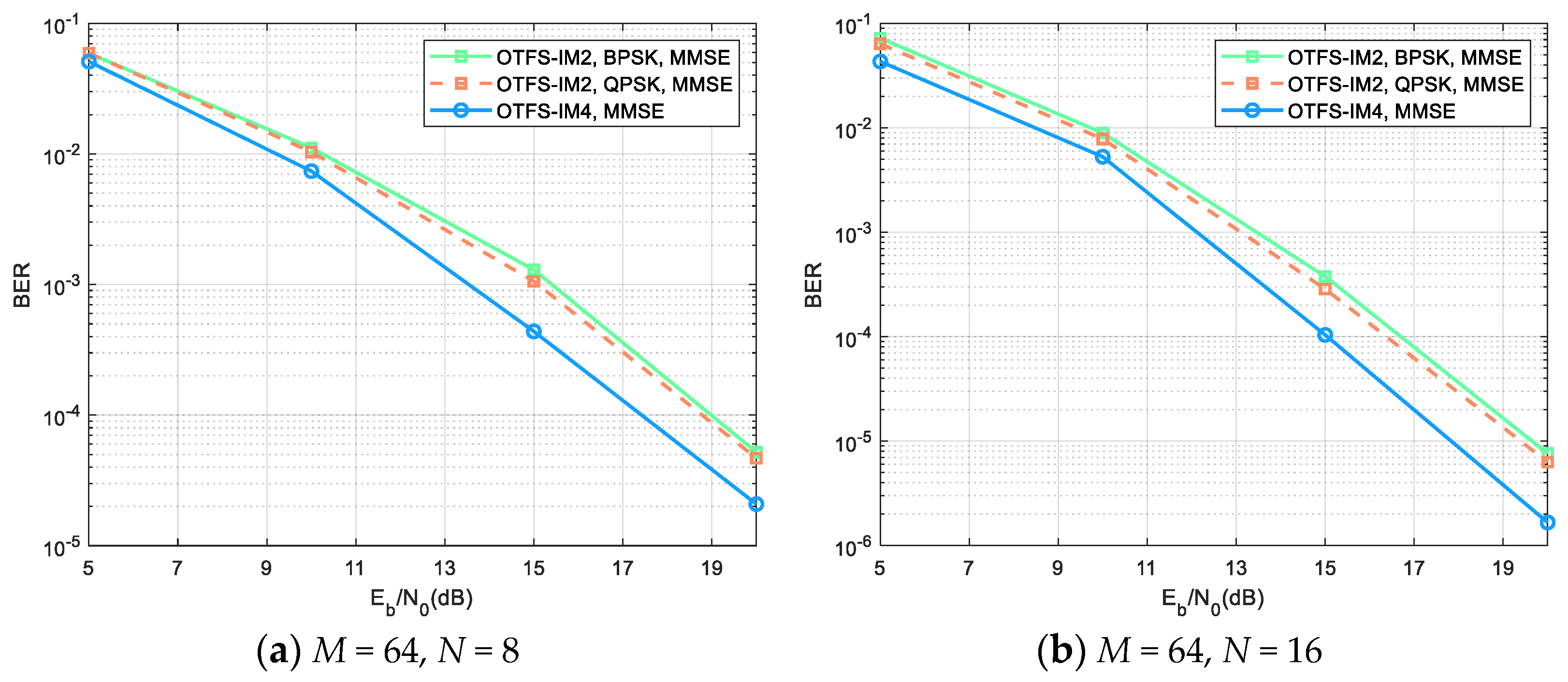
Additionally, we also simulate the BER performance of these two schemes in the EVA channel to verify the generality of the proposed scheme while the other parameters are the same as the two-path channel. It can be seen in
Figure 5a that the four-dimensional modulation is still better than the two-dimensional modulation. For example, the OTFS-IM4 scheme achieves about 1.5 dB gain more than the OTFS-IM2 scheme when
. Moreover, when QPSK is adopted in the two-dimensional modulation, the spectral efficiency is
, and the BER performance coincides with BPSK, which is the same conclusion as in the AWGN channel.
Figure 5b demonstrates a comparison between the proposed scheme and BPSK and QPSK under the EVA channel, considering an increased number of symbols within an OTFS frame. The only difference from the conditions in
Figure 5a is that the size of an OTFS frame is changed to
M = 64,
N = 16. At this time, the number of symbols in a frame is
. The same conclusion is reached as shown in
Figure 5a. Due to the Doppler resolution
, the Doppler resolution improves when
N increases. Therefore, the BER performance also improves accordingly, which explains the difference between the two figures. Results show that the proposed scheme is also applicable when the channel is more complex, which verifies the robustness and generality of the OTFS-IM scheme with four-dimensional spherical code.
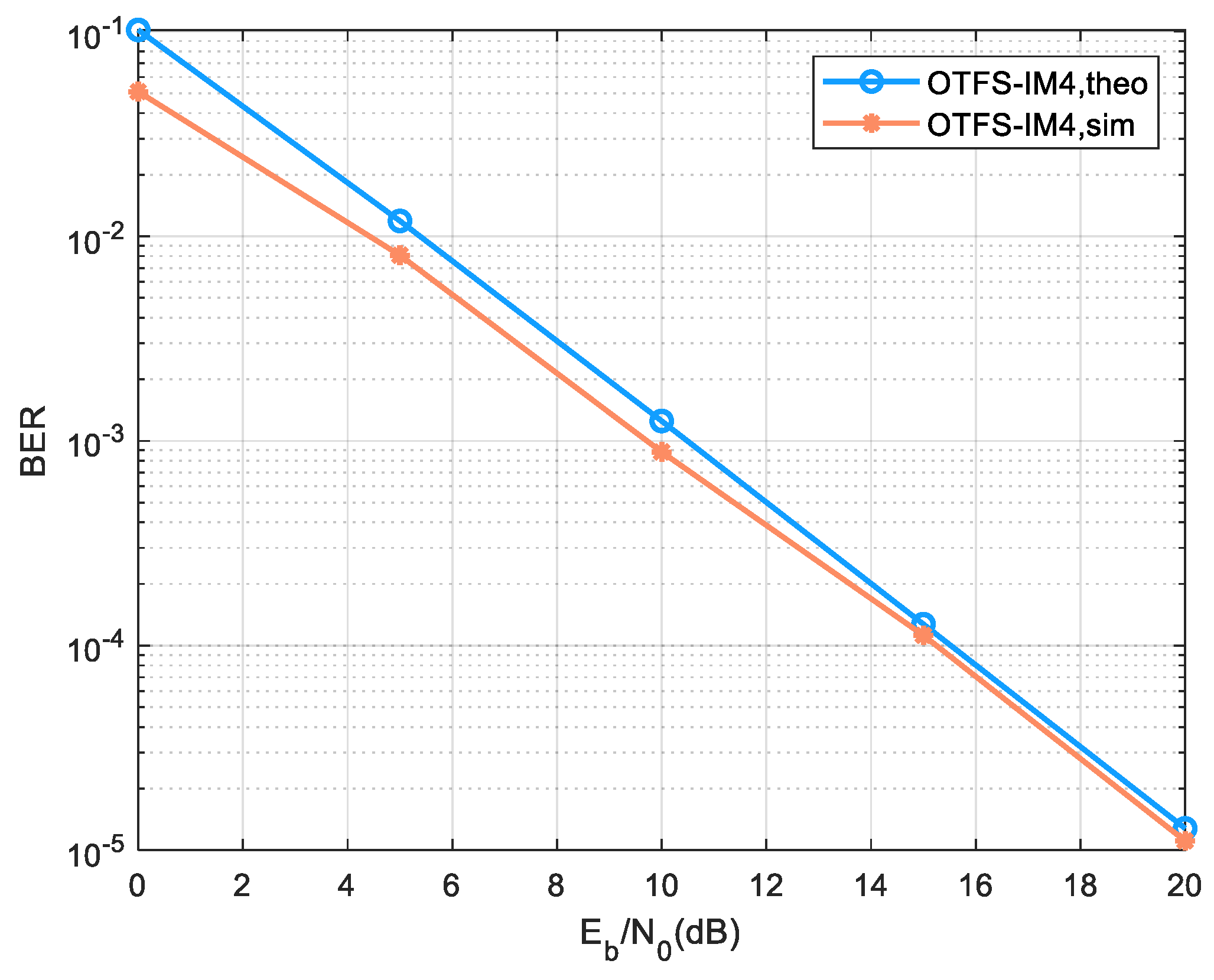
The comparison of theoretical values and simulation results for BER and PAPR performance in the OTFS-IM4 system are well illustrated in the following. First, the BER comparison is shown in
Figure 6. Since the derived BER theoretical value needs to traverse the entire signal space, the calculation complexity of the theoretical value is relatively high. In order to facilitate the solution, the simulation parameters are specified as follows. The OTFS frames are simplified to
and
. Since the symbol duration
and the subcarrier spacing
determine the maximum delay
and maximum Doppler
that can be supported for the channel [
31], we adapt the channel state to
and
. Other parameters are the same as in the four-dimensional modulation. There is exactly one sub-block in a frame in this case, i.e.,
,
, and
. It can be seen that the simulation results and the theoretical values become closer as
increases, which verifies the correctness of the derived BER performance.
Next,
Figure 7 simulates the CCDF of the PAPR for different OTFS schemes and different sub-block situations. The theoretical analysis results show that PAPR in the OTFS system is related to the parameter
, while in the OTFS-IM system, PAPR is also related to the proportion of the active symbols in the sub-block. Therefore, different
values are simulated to verify the analysis results. We take
and
for an example. Meanwhile, BPSK modulation is still used in the OTFS-IM2 system. When
, the simulation results are as shown in
Figure 7a, and there is the following specific analysis. The spectral efficiency of the two solid curves is
. It can be seen that the PAPR performance of the OTFS-IM2 is similar to that of the OTFS-IM4. When the spectral efficiency is
, as shown by the two dashed lines, the PAPR performance of the OTFS-IM4 is about 0.1 dB better than that of the OTFS-IM2. As for the theoretical analysis in
Section 3, the PAPR performance of these two schemes is only slightly different. In addition, it is proved that the PAPR increases linearly with the proportion
of active symbols in a sub-block. Theoretically, the PAPR with
is 3 dB smaller than with
, which corresponds to the simulation results. For
, the simulation results are depicted in
Figure 7b. Although there are slight differences in performance compared with that in
Figure 7a, the trend is the same. When
, the PAPR with
is approximately equal in OTFS-IM2 and OTFS-IM4, and the four-dimensional modulation has 0.1 dB gain over two-dimensional modulation at
. Comparing
Figure 7a,b horizontally, PAPR increases by 3 dB with the doubling of
when spectral efficiency is the same, which is also consistent with the theoretical analysis. Additionally, the PAPR of the OTFS system is proportional to
but has a threshold.


