Abstract
Due to the hostile marine environment, there will inevitably be unpredictable factors during the operation of unmanned underwater vehicles, including changes in ocean currents, hull dimensions, and velocity measurement uncertainties. An improved finite-time adaptive tracking control issue is considered for autonomous underwater vehicles (AUVs) with uncertain dynamics, unknown external disturbances, and unavailable speed information. A state observer is designed to estimate the position and velocity of the vehicle via a neural network (NN) approach. The NN is used to estimate uncertainties and external disturbances. A finite-time controller is designed via backstepping and command filter techniques. A multi-input multi-output (MIMO) filter for AUVs is established, and the corresponding MIMO filter compensation signal is constructed to eliminate the effect of filtering error. All the signals of the closed-loop system are proved to be finite-time bounded. An example with comparison is given to show the effectiveness of our method.
1. Introduction
With the development of marine environment monitoring, marine rescue, and other applications, the research on unmanned vehicles (UV) [1,2,3,4,5,6,7] has attracted more attention. Due to the complexity of ocean currents and many uncertainties in the marine environment, the controller of the UV is required to have strong robustness. As a category of UV, AUV has grown with the development of marine science. AUV is the product of multiple disciplines, including mechanics, control, communication, artificial intelligence, and others. Due to its characteristics of long mission endurance, wide range of activities, high safety factor, and low cost, AUVs have been widely considered. AUVs can perform tasks such as underwater early warning, marine environment monitoring, and rescue at sea. The use of AUVs in these fields can significantly reduce the harm to divers and improve the efficiency of mission accomplishment. To accomplish such tasks, AUVs are required to have good maneuverability in complex environments and to complete the localization and tracking tasks accurately and efficiently. The stability and robustness of the control system have a significant impact on whether the AUV can operate safely in the complex and changing marine environment. Due to the particularity of the system, control methods such as full-state feedback linearization are not applicable, which makes the controller design of AUVs challenging.
In order to improve control efficiency, PID control [8], backstepping control [9], sliding mode control (SMC) [10,11], and other control methods are proposed. Among them, the backstepping method can simplify the controller design process of AUVs and is widely used [1,2]. The traditional backstepping method requires continuous differentiation of a virtual function, which goes against the design principle of low cost for AUVs. Because the design of the backstepping method requires the derivative of the virtual control law at each step, the number of terms in the virtual control law and the corresponding controller complexity will both rise. This will have a significant impact on the applicability of the backstepping method in systems with microcontrollers, such as UVs. Considering this, a dynamic surface control algorithm is presented. By incorporating a first-order filter into the backstepping controller design, the partial differential operation used in the virtual controller design is converted into a simple algebraic operation, reducing the amount of computation. The dynamic surface approach was applied to eliminate the repetitive derivation behavior in the virtual control law of the backstepping method, and an ocean current disturbance observer was designed to produce a feedforward compensation of the UV [12]. An auxiliary dynamic system with dynamic surface technique was proposed in [13] to deal with the input constraints of UV. The controller for the fully actuated surface vehicle was designed in [14] by means of a recursive dynamic surface approach, and a smooth hyperbolic tangent function was applied to reduce the probability of actuator saturation. However, the filtering error caused by increasing the filter tends to cause oscillations or even divergence in closed-loop systems, which makes the design of the filter constants very difficult. The inclusion of a filter error compensation signal in the backstepping design process eliminates the effect of filter error on the control performance. A command filter-based tracking control scheme was proposed to reduce the computational load of the backstepping method and remove the high-frequency measurement noise [15]. The command filter adaptive control was introduced to construct the human–machine collaborative control strategy [16]. A collaborative path-tracking controller was designed for a group of autonomous underwater vehicles with nonlinear uncertainties. The command filter control technique was used to eliminate the assumption of the second derivative of the reference path [17].
Meanwhile, there are many uncertainties in UV dynamic models, such as ocean current disturbance, unknown hydrodynamic parameters, and unmodeled dynamics [18,19,20,21]. Many control methods have been proposed to approximate system uncertainties. For the navigational high-precision tracking tasks, an event-triggered adaptive tracking control for underactuated vehicles was proposed [22]. The minimum learning parameters of NN were applied to estimate the disturbances and uncertainties. The tracking control problem was considered for surface vehicles in terms of NN [23]. An onboard support for vessels that provides position predictions was proposed in terms of a machine learning model [24]. A dynamic positioning control for vessels with uncertainties and disturbances was investigated in [25] via the adaptive NN control method.
On another research front, as a powerful control method, NNs are widely used in nonlinear tracking control systems. In fact, due to the cost and size of AUVs, it is difficult for sensors inside them to obtain speed information in harsh marine environments. A nonlinear disturbance observer was proposed to deal with the roll motion’s effect and uncertain nonlinear model features of AUVs [26]. The extended state observer was constructed in [27] to estimate the unknown velocities and disturbances of marine surface vessels and a finite-time output feedback controller was obtained. Combined with the dynamic surface control, a homogeneous nonlinear extended state observer was designed to deal with the trajectory tracking issue for UVs [28]. To estimate the unmeasured state of vehicles, an adaptive fuzzy state observer was proposed in [29], and the chattering effect was eliminated by an improved SMC method. The bio-inspired state observer was established to estimate the unknown velocities, and a robust output-feedback controller was designed to ensure the heading converges to desired values [30]. An NN-based observer was constructed to estimate the state, sensor faults, and actuator failures of the AUVs [31]. In [32], an adaptive observer was designed to estimate the follower velocities of the AUVs, and reduce the risk of the actuator saturation. Also, the fuzzy adaptive finite-time control (FTC) for vessels with uncertainties was considered via the SMC method [33].
Furthermore, compared with asymptotic stability, the FTC scheme proposed in [34] improves the convergence speed and anti-interference of systems. The FTC algorithm has a fractional power term, which gives it the advantages of fast convergence, high control precision, and good anti-interference performance [35]. From another perspective, the use of finite-time tracking control schemes can improve the robustness of AUV systems. The tracking problem of AUVs in [36] was studied via an adaptive control law that updates the upper bounds of the disturbances. The optimal fuzzy tracking control for vessels under uncertainties and disturbances was considered in [37] by constructing a finite-time disturbance observer. The FTC for a coaxial octorotor with disturbances was investigated via the SMC approach [38]. A novel hyperbolic-tangent path following the FTC problem was studied for AUVs subject to disturbances and internal dynamics in [39]. An output feedback cooperative formation problem for surface vessels was studied in [40]. At the same time, the nonlinear extended state observer is constructed to compensate the unknown time-varying actuator faults and realize the finite-time tracking control. For uncertain nonlinear AUV systems with input saturation, the finite-time terminal sliding surfaces control strategy was established to guarantee the boundedness of tracking error [41]. In order to avoid formation collision and maintain path connectivity, an extended observer was designed to recover unmeasured velocity signals and realize maneuvering formation mode in a finite time [42]. The fault-tolerant formation control of the surface AUV was completed in a finite time via using the restricted line-of-sight range and angle tracking error [43].
Inspired by the above discussion, considering simultaneous unmodeled dynamics, the unavailability of speed, and unknown time-variant marine environment disturbances, an adaptive finite-time tracking control approach is proposed. An NN is introduced to estimate the uncertainty, and an observer is established to approximate the unavailable velocity. The “complexity explosion” issue is solved in terms of a second-order command filter. The main contributions are summarized below.
- (1)
- The FTC of the AUV is realized via output feedback control and backstepping method, which ensures control precision. The velocity of the AUV is observed by a designed high-gain state observer. In contrast with [44], the design of the observer in this paper requires fewer hydrodynamic parameters and lower requirements for the AUV. At the same time, the assumption of [44] on the AUV’s velocity is relaxed.
- (2)
- In order to reduce the requirement for dynamic accuracy, the adaptive NN is used to approximate the unknown parameters of the AUV and eliminate the influence of time-varying external disturbances. Compared with [23,24,25], the FTC for the AUV is considered, and the state of the error system is proved to converge to a small neighborhood of zero within a finite time interval, which can better meet the task requirements of UVs. The designed finite time controller also increases the robustness of the AUV system.
- (3)
- Different from other command-filters designed for AUVs [15,16,17], a MIMO filter compensation signal based on the transformation matrix of the AUV was designed to eliminate the influence of filtering errors, avoid the chattering phenomenon, and relax the restrictions on the virtual control signal. The stability of the closed-loop system is analyzed, the computational complexity caused by the backstepping approach is reduced in terms of the command filter, and the filtering compensation loop is established to reduce the error caused by the second-order filter. The effective tracking performance of the control scheme considering external disturbance is verified by a simulation.
2. Problem Formulation
In order to ensure that the AUV can complete the tracking task, we first study the dynamics modeling of the AUV. A reasonable design of a dynamic model is helpful in analyzing the system state of the AUV and gives the relationship between the velocity, position, and other states of the vehicle. At the same time, the design of a dynamic model is also the basis and premise of the research on tracking control of AUV.
To simplify the design of the controller, we assume that the kinematics and the dynamics models of the AUV are symmetric, and the interference of the nonlinear dynamics model is taken into account. Taking AUVs as rigid bodies, we establish the following dynamic model in Figure 1, which depicts the reference frame for AUV path tracking in the plane:
where denotes the position and heading angle , is the velocities of surge, sway, and yaw, respectively. The variable definitions in the system model are given in Table 1. n is the number of degrees of freedom of the AUV.
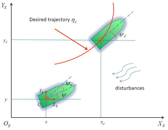
Figure 1.
Reference frames of AUVs.

Table 1.
The variables and meanings in the model.
Remark 1.
According to (2), a coordinate transformation matrix appears in the design process of the controller, which brings some difficulties. From the elements in the coordinate transformation matrix, it can be seen that the matrix is about the sin and cos functions. It is noted that the sin function and the cos function are both bounded functions, so we can conclude that the transformation matrix is also bounded. At the same time, we can also obtain . When designing the virtual controller (21), is used, which does not produce excessive controller output behavior.
Combining the characteristics of the marine environment and the vehicle, three factors that affect the vehicle dynamics model are summarized: The first one is the external ocean disturbance, which causes the nonlinear damping dynamic parameter perturbation in the dynamic model. Secondly, the change in vehicle structure will cause uncertainty in the vehicle dynamic model, and the movement of the vehicle will also cause a change in hydrodynamic parameters. The third is the unknown velocity of the AUV. The controller design usually requires the AUV’s velocity signal, but due to communication delays and ocean noise, some of the velocity signals will be missing. At the same time, changes in load conditions, attitude, and external disturbances will also cause difficulties in the speed measurement of sensors. In addition, the measurement noise makes it difficult for the internal sensor of the AUV to obtain velocity information in the harsh marine environment. Due to the cost control of the AUV, the sensor accuracy is low, and it is difficult to ignore the influence of marine noise. Therefore, we should get rid of the dependence on the velocity measurement unit in the design of the AUV tracking controller so as to improve the robustness of the AUV.
Our objective is to investigate the trajectory control of AUVs and to design the control law and the observer for system (1). Under this control scheme, effective velocity observation and position tracking can be achieved in the presence of unknown nonlinear dynamics , D, and ocean current disturbances.
Assumption 1.
Inertia matrix M is bounded, which satisfies , with m being a positive constant.
Assumption 2.
The disturbance vector d represents external perturbations such as currents or winds. d is unknown, continuously time-varying, and bounded.
Lemma 1.
([34]). For continuous function , and system , , . There is a continuous Lyapunov function such that:
- f is a positive definite function;
- There exist real numbers , , and , and an open neighborhood of the origin such that holds. Then, the origin is finite-time stable and the settling time is .
Lemma 2.
(Young’s inequality) ([45]). and , then we have
Lemma 3.
where x is the input, denotes the output layer weight, and is the output of hidden layer. is the number of hidden nodes. represents the commonly used Gaussian function, where , and denotes the center vector and the width of the Gaussian function, respectively.
([23]). Consider a continuous function , where is compact. Given a constant , there exists a radial basis function neural network such that
Lemma 4.
([46]). Suppose is a continuous piece-wise quadratic differentiable input signal. There exists , such that , where , , between and is the estimation of .
Lemma 5.
([45]). There exist constants , and
Remark 2.
Compared with velocity information, the position information of the AUV can be obtained cheaply and directly. Its position information can be obtained with the help of GPS, and its yaw can be measured by a compass. Therefore, we assume that the x, y, and ψ information of the AUV is known, which is a very common assumption.
3. Main Results
3.1. State Observer-Based Trajectory Controller Design
In the actual complex marine environment, the velocity of the AUV is often unmeasured. In this section, an observer is designed in terms of the NN method.
For the convenience of design, the AUV model (1) is redescribed as
Define , then
According to Lemma 3, we can obtain , , then it follows that
To observe the unmeasured signal, the state observer is designed as:
where , , then we have
By Lemma 5, . Define , the error dynamics (7) is rewritten as
where
where A belongs to the Hurwitz matrix category, there exists a symmetric matrix P, and .
For (8), we select the Lyapunov function as
so the derivative of :
then
where . We have
Substituting (9) into (12), it can be obtained that
where , , R is positive constant.
The uncertain model parameters of the system could potentially affect the tracking control performance of the AUV. In (5), the radial basis function of NN is applied to estimate the nonlinear term of the AUV and, on this basis, a finite-time NN state observer is designed to improve the robustness and quickly estimate the velocity of the AUV. Compared with the traditional NN state observer, the observer in this paper has a simple structure and a faster output response, and the proof is given by (13). Compared with [44], the structure of our designed observer is simple, which relaxes the assumption that the velocity of the AUV needs to be known. In the later proof, the velocity of the AUV is proved to be bounded. Although the assumption of velocity upper bound is reasonable, the selection of an inappropriate speed upper bound will still affect the controller design of the AUV.
Remark 3.
Neural networks have the ability to approximate arbitrary nonlinear functions and are highly fault-tolerant when dealing with problems such as nonlinear systems with uncertain parameters. However, it also brings some problems. Neural networks rely on initial values, they have poor convergence and, at the same time, they are computationally intensive.
Remark 4.
From (13) and Lemma 1, it is obvious that the observer can complete the finite-time estimation of forward velocity, lateral velocity, and yaw rate.
The observer error is finite-time bounded, which means that the designed state observer is effective. In the following, the finite-time tracking controller of the AUV will be constructed.
3.2. Command Filter-Based Feedback Controller Design for AUVs
By means of the backstepping approach, a state observer is designed, and the output feedback controller combined with the command filter is proposed. The calculation cost of the virtual controller is reduced via a command filter in the design process as follows:
The framework for the AUV position tracking problem is shown in Figure 1. denote the geodetic fixed frame and denote the body fixed frame, where represents the expected trajectory.
Our control goal is to design the control force and control force moment so that the position error converges to a small region near zero over a finite time interval.
Firstly, the following coordinate transformation is established to transform the tracking control problem of the AUV into a tracking error finite-time bounded problem. In the coordinate design of the traditional backstepping method, the second term of the coordinate transformation is , which will lead to the complexity of the control structure [17]. In this paper, we use as the input of the command filter and replace with the output of the filter . At the same time, the command filter error compensation signal is added to the coordinate transformation to ensure that converges to a small region near zero within a finite time interval to ensure that the AUV can complete the tracking control in a finite time.
Define the tracking errors as
when the virtual controller is the input, denotes the output of the first-order Levant differentiator. The finite-time command filter is constructed as:
in which is the input and is the output, where and are positive constants.
In contrast to the asymptotic command filter, the finite-time command filter can estimate the derivative of the virtual controller in a finite time interval, which guarantees a fast corresponding output of the filter. At the same time, the similarity of the arctan function and the sign function is applied to replace the sign function in the filter and reduce the chattering phenomenon.
The compensated tracking errors are defined as
The error compensating signals are defined as follows:
where and are positive constants, r is a positive constant and .
The finite-time backstepping control is established as follows:
It can be seen from (19) and (20) that the filter compensation signal designed in this manuscript is a function with MIMO, which is to eliminate the coupling phenomenon caused by the rotation matrix of the AUV. The general command filter compensation signal design would normally use coordinate conversion to avoid the current situation, but because the AUV rotation matrix has a coupling phenomenon, the conversion matrix is difficult to design. Regarding this problem, in [15,16,17], a special compensation signal was not designed, and the filtering error generated by the command filter was not considered. Therefore, in this paper, it is the first time that the finite-time command filter compensation signal has been constructed in the AUV controller design, and the rationality of the command filter error compensation signal design is verified by the following deductive process and simulation.
In this section, the single-input single-output command filter is extended to the MIMO filter. It can be seen from (15), (17), (19), and (20) that this is a MIMO command filter and error compensation signal. The influence of the transformation matrix on the design of the command filter is eliminated. The transformation between the navigation body and the geodetic coordinate system is complete.
Theorem 1.
Considering the AUV system model (3) with tracking control law (21) and (22), the adaptive law (32), and the observer (6), the tracking errors(14) are adjusted near zero with a small region in a finite time.
Proof.
The following steps can work out the desired result:
Define the Lyapunov function as:
Taking the derivative of yields
Substituting and , it follows that
where , , r are the positive constants to be designed.
By using Young’s inequality, there holds
where is an unknown positive constant to be given.
Then,
Choose the Lyapunov function as:
According to (29), we have
Substituting , it follows that
The adaptive law of is
where and are the unknown constants to be designed.
By Young’s inequality, there holds
Then,
According to (28) and (36), we have
where .
By Lemma 2, one has
Substituting (38) into (37), it yields
where
For compensating system (18), choose
Then, it follows that
by using Lemmas 2 and 4, we have
Then it follows that
where , and are the unknown positive constants to be designed. Then, we choose
According to (13), (39), and (43), computing derivative of V yields
in which
Furthermore, (45) is equivalent to the following inequality
where . If , then .
From Lemma 1, and will converge into
in finite time . When , it follows that . Similarly,
in finite time .
Therefore, the finite-time semi-globally uniformly ultimately boundedness of all signals in the closed-loop system is guaranteed.
It follows that will converge into the region
in finite-time . For , finally, reaches to
This means that the output tracking error can be regulated arbitrarily small within a finite time T on the choice of the appropriate parameters.
According to the above proof, it is obvious that , so that, is bounded. From the expression of (21), we can obtain that is a function containing , , , and . It means that is bounded. Similarly, . From Lemma 4, we can obtain that is bounded; therefore, is obviously bounded. We know that , then it follows that is bounded. is a function containing , , , , , , and . From Lemma 3, we know that is bounded. Thus, the boundedness of all signals is proved. □
Remark 5.
In traditional backstepping design, the real controller is obtained by repeatedly differentiating the virtual controller. Due to the coupling structure, direct derivation will make the controller structure of the AUV very complicated. The derivation of the virtual control law with coupling structure is avoided by means of introducing a command filter. However, the introduction of filters will inevitably produce filtering errors, which will reduce the tracking and control performance of the AUV. In view of this, a new filter compensation scheme is considered in this paper that can eliminate the filtering error while satisfying the finite-time boundedness requirement.
4. Example
A three-degree-of-freedom all-wheel-drive AUV simulation is used to verify the feasibility of our controller and filter design. This AUV, depicted in Figure 1, performs standard circular maneuvers at constant depth with the major parameters shown below, and other model parameters taken from [47]:
where
The desired trajectory of AUV is
The main parameters are as follows: , , , , , , r = , , , , , m, m, , ,
Figure 2 is the expected and actual trajectories of AUV in the geodetic coordinate system. Figure 3 shows the desired and actual positions of the AUV. Figure 4 is the duration curve of the expected yaw angle and the actual yaw angle. Figure 5, Figure 6 and Figure 7 show the observations of AUV’s forward velocity u, v, and yaw angular velocity r. In Table 2, more details of the distance of the AUV from the intended trajectory are shown. It shows that the tracking error converges within a small domain around zero. It is obvious that the designed observer can well observe each component of the actual velocity vector. It is obvious that the designed controller can complete the tracking task in a finite time. Our control algorithm is effective.
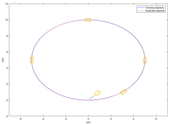
Figure 2.
The actual trajectory and reference trajectory.
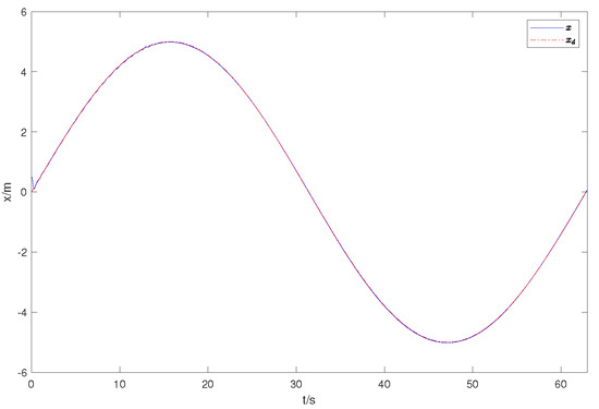
Figure 3.
The actual and expected position.
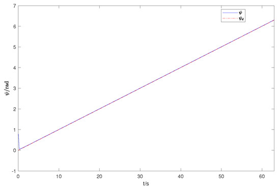
Figure 4.
The actual and expected position yaw angle.
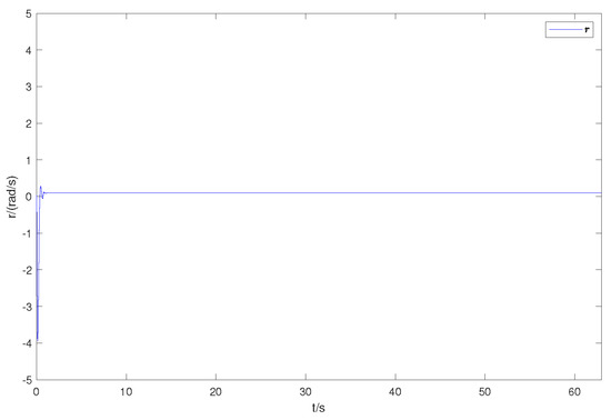
Figure 5.
The observer estimation of yaw angular velocity.
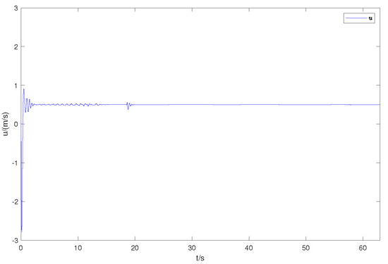
Figure 6.
The observer estimation of forward velocity.
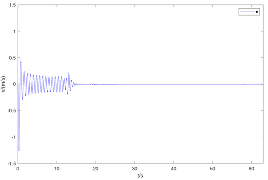
Figure 7.
The observer estimation of lateral velocity.

Table 2.
The position tracking error.
Further, an experimental comparison with [48] is used to demonstrate the effectiveness of our controller design. Here, we use a new initial position parameter m, m, and keep the other parameters unchanged. We illustrate the robustness of the controller design using root mean square error (MSE) calculations. Without considering the effect of input saturation, the designed controller outperforms the controller in [48] using the same starting point and the same parameters. The MSE in Table 3 represents the tracking performance of the two controllers. Figure 8 indicates that the two controllers have different tracking performance.

Table 3.
Tracking performance comparison of MSE.
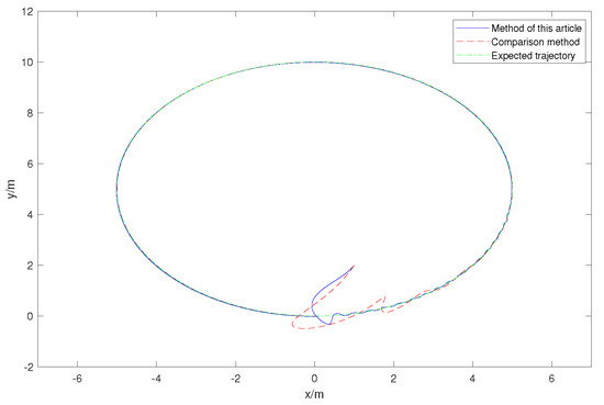
Figure 8.
The trajectory in XOY plane.
5. Conclusions
The finite-time tracking control of AUVs in complex marine environments has been studied in this paper. The nonlinear dynamics model of the AUV has been established. According to the characteristics of the AUV, the influences of external disturbance, the determination of model parameters, and unknown vehicle velocity on the design of the AUV controller have been considered. Neural networks are utilized to estimate the disturbances and parameter uncertainties and eliminate their effects on the controller design. The forward, lateral, and yaw angular velocities of the vehicle have been approximated by constructing a state observer, which reduces the use of speed sensors, lowers the manufacturing cost of the vehicles, and improves the lifetime of the vehicle. The command filter has been introduced to reduce the number of deviation calculations in the design process, simplify the controller structure, reduce the calculation amount of the embedded computer in the AUV, reduce power consumption, and increase the cruise time of the AUV. Due to the size and cost constraints of the AUV, our future work will aim to simplify the controller structure, reduce the controller communication frequency, and optimize the thruster output power distribution in order to reduce power consumption and increase the efficiency ratio of the AUV.
Author Contributions
J.G.: Conceptualization, Methodology, Software, Investigation, Writing—Original Draft; J.W.: Resources, Writing—Review and Editing; Y.B.: Validation, Writing—Review, Supervision. All authors have read and agreed to the published version of the manuscript.
Funding
This research received no external funding.
Data Availability Statement
Not applicable.
Conflicts of Interest
The authors declare no conflict of interest.
References
- Shojaei, K.; Dolatshahi, M. Line of sight target tracking control of underactuated autonomous underwater vehicles. Ocean Eng. 2017, 133, 244–252. [Google Scholar]
- Heshmati-Alamdari, S.; Nikou, A.; Dimarogonas, D.V. Robust trajectory tracking control for underactuated autonomous underwater vehicles in uncertain environments. IEEE Trans. Autom. Sci. Eng. 2020, 18, 1288–1301. [Google Scholar] [CrossRef]
- Polvara, R.; Sharma, S.; Wan, J.; Manning, A.; Sutton, R. Vision-based autonomous landing of a quadrotor on the perturbed deck of an unmanned surface vehicle. Drones 2018, 2, 15. [Google Scholar] [CrossRef]
- Wang, J.; Xia, L.; Peng, L.; Li, H.; Cui, Y. Efficient uncertainty propagation in model-based reinforcement learning unmanned surface vehicle using unscented kalman filter. Drones 2023, 7, 288. [Google Scholar]
- Liu, W.; Xu, J.; Li, L.; Zhang, K.; Zhang, H. Adaptive model predictive control for underwater manipulators using Gaussian process regression. J. Mar. Sci. Eng. 2023, 11, 1641. [Google Scholar]
- Rybczak, M.; Gierusz, W. Maritime autonomous surface ships in use with LMI and overriding trajectory contol. Appl. Sci. 2022, 12, 9927. [Google Scholar]
- Herman, P. Numerical test of several controllers for underactuated underwater vehicles. Appl. Sci. 2020, 10, 8292. [Google Scholar] [CrossRef]
- Kang, B.; Miao, Y.; Liu, F.; Duan, J.; Wang, K.; Jiang, S. A second-order sliding mode controller of quad-rotor UAV based on PID sliding mode surface with unbalanced load. J. Syst. Sci. Complex. 2021, 34, 520–536. [Google Scholar] [CrossRef]
- Le, W.; Liu, H.; Zhao, R.; Chen, J. Attitude control of a hypersonic glide vehicle based on reduced-Order modeling and NESO-assisted backstepping variable structure control. Drones 2023, 7, 119. [Google Scholar]
- Elmokadem, T.; Zribi, M.; Youcef-Toumi, K. Trajectory tracking sliding mode control of underactuated AUVs. Nonlinear Dyn. 2015, 84, 1079–1091. [Google Scholar] [CrossRef]
- Yan, Z.; Wang, M.; Xu, J. Robust adaptive sliding mode control of underactuated autonomous underwater vehicles with uncertain dynamics. Ocean Eng. 2019, 173, 802–809. [Google Scholar]
- Shen, Z.; Wang, Q.; Dong, S.; Yu, H. Prescribed performance dynamic surface control for trajectory-tracking of unmanned surface vessel with input saturation. Appl. Ocean Res. 2021, 113, 102736. [Google Scholar]
- Shen, Z.; Wang, Q.; Dong, S.; Yu, H. Dynamic surface control for tracking of unmanned surface vessel with prescribed performance and asymmetric time-varying full state constraints. Ocean Eng. 2022, 253, 111319. [Google Scholar]
- Shen, Z.; Bi, Y.; Wang, Y.; Guo, C. MLP neural network-based recursive sliding mode dynamic surface control for trajectory tracking of fully actuated surface vessel subject to unknown dynamics and input saturation. Neurocomputing 2020, 377, 103–112. [Google Scholar] [CrossRef]
- Wang, J.; Wang, C.; Wei, Y.; Zhang, C. Command filter based adaptive neural trajectory tracking control of an underactuated underwater vehicle in three-dimensional space. Ocean Eng. 2019, 180, 175–186. [Google Scholar]
- Zhang, J.; Wu, J.; Liu, J.; Zhou, Q.; Xia, J.; Sun, W.; He, X. Command-filter-adaptive-based lateral motion control for autonomous vehicle. Control Eng. Pract. 2022, 121, 105044. [Google Scholar] [CrossRef]
- Wang, H.; Tian, Y.; Xu, H. Neural adaptive command filtered control for cooperative path following of multiple underactuated autonomous underwater vehicles along one path. IEEE Trans. Syst. Man Cybern. Syst. 2022, 52, 2966–2978. [Google Scholar] [CrossRef]
- Liang, H.; Li, H.; Xu, D. Nonlinear model predictive trajectory tracking control of underactuated marine vehicles: Theory and experiment. IEEE Trans. Ind. Electron. 2021, 68, 4238–4248. [Google Scholar]
- Deng, Y.; Zhang, X.; Im, N.; Zhang, G.; Zhang, Q. Adaptive fuzzy tracking control for underactuated surface vessels with unmodeled dynamics and input saturation. ISA Trans. 2020, 103, 52–62. [Google Scholar] [CrossRef]
- Shojaei, K. Neural network feedback linearization target tracking control of underactuated autonomous underwater vehicles with a guaranteed performance. Ocean Eng. 2022, 258, 111827. [Google Scholar]
- Lamraoui, H.C.; Qidan, Z. Path following control of fully-actuated autonomous underwater vehicle in presence of fast-varying disturbances. Appl. Ocean Res. 2019, 86, 40–46. [Google Scholar]
- Deng, Y.; Zhang, Z.; Gong, M.; Ni, T. Event-triggered asymptotic tracking control of underactuated ships with prescribed performance. IEEE Trans. Intell. Transp. Syst. 2023, 24, 645–656. [Google Scholar] [CrossRef]
- He, W.; Yin, Z.; Sun, C. Adaptive neural network control of a marine vessel with constraints using the asymmetric barrier Lyapunov function. IEEE Trans. Cybern. 2017, 47, 1641–1651. [Google Scholar] [CrossRef]
- Skulstad, R.; Li, G.; Fossen, T.I.; Vik, B.; Zhang, H. A hybrid approach to motion prediction for ship docking—Integration of a neural network model into the ship dynamic model. IEEE Trans. Instrum. Meas. 2020, 70, 2501311. [Google Scholar] [CrossRef]
- Li, J.; Xiang, X.; Yang, S. Robust adaptive neural network control for dynamic positioning of marine vessels with prescribed performance under model uncertainties and input saturation. Neurocomputing 2022, 484, 1–12. [Google Scholar]
- Thanh, P.N.N.; Tam, P.M.; Anh, H.P.H. A new approach for three-dimensional trajectory tracking control of under-actuated AUVs with model uncertainties. Ocean Eng. 2021, 228, 108951. [Google Scholar] [CrossRef]
- Zhang, J.; Yu, S.; Yan, Y. Fixed-time extended state observer-based trajectory tracking and point stabilization control for marine surface vessels with uncertainties and disturbances. Ocean Eng. 2019, 186, 106109. [Google Scholar]
- Cao, H.; Xu, R.; Zhao, S.; Li, M.; Song, X.; Dai, H. Robust trajectory tracking for fully-input-bounded actuated unmanned surface vessel with stochastic disturbances: An approach by the homogeneous nonlinear extended state observer and dynamic surface control. Ocean Eng. 2022, 243, 110113. [Google Scholar] [CrossRef]
- Li, M.; Long, Y.; Li, T.; Bai, W. Observer-based adaptive fuzzy event-triggered path following control of marine surface vessel. Int. J. Fuzzy Syst. 2021, 23, 2021–2036. [Google Scholar]
- Tuo, Y.; Wang, S.; Guo, C.; Gao, S.S. Robust output feedback control for dynamic positioning of turret-moored vessels based on bio-inspired state observer and online constructive fuzzy system. Int. J. Nav. Archit. Ocean Eng. 2022, 14, 100440. [Google Scholar] [CrossRef]
- Chen, L.; Liu, M.; Shi, Y.; Zhang, H.; Zhao, E. Adaptive fault estimation for unmanned surface vessels with a neural network observer approach. IEEE Trans. Circuits Syst. I Reg. Pap. 2021, 68, 416–425. [Google Scholar] [CrossRef]
- Shojaei, K. Observer-based neural adaptive formation control of autonomous surface vessels with limited torque. Robot. Auton. Syst. 2016, 78, 83–96. [Google Scholar]
- Hosseinabadi, P.A.; Abadi, A.S.A.; Mekhilef, S. Fuzzy adaptive finite-time sliding mode controller for trajectory tracking of ship course systems with mismatched uncertainties. Int. J. Autom. Control 2022, 16, 255–271. [Google Scholar] [CrossRef]
- Li, S.; Du, H.; Lin, X. Finite-time consensus algorithm for multi-agent systems with double-integrator dynamics. Automatica 2011, 47, 1706–1712. [Google Scholar] [CrossRef]
- Chen, B.; Hu, J.; Zhao, Y.; Ghosh, B.K. Finite-time observer based tracking control of uncertain heterogeneous underwater vehicles using adaptive sliding mode approach. Neurocomputing 2022, 481, 322–332. [Google Scholar]
- Ali, N.; Tawiah, I.; Zhang, W. Adaptive finite-time trajectory tracking event-triggered control scheme for underactuated surface vessels subject to input saturation. IEEE Trans. Intell. Transp. Syst. 2023, 24, 8809–8819. [Google Scholar]
- Gao, X.; Long, Y.; Li, T.; Hu, X.; Chen, C.L.P.; Sun, F. Optimal fuzzy output feedback control for dynamic positioning of vessels with finite-time disturbance rejection under thruster saturations. IEEE Trans. Fuzzy Syst. 2023. [Google Scholar] [CrossRef]
- Amin, R.; Inayat, I.; Jun, L.A. Finite time position and heading tracking control of coaxial octorotor based on extended inverse multi-quadratic radial basis function network and external disturbance observer. J. Frankl. Inst. 2019, 356, 4240–4269. [Google Scholar]
- Wang, N.; Ahn, C.K. Hyperbolic-tangent LOS guidance-based finite-time path following of underactuated marine vehicles. IEEE Trans. Ind. Electron. 2020, 67, 8566–8575. [Google Scholar] [CrossRef]
- Wang, P.; Yu, C.; Pan, Y. Finite-time output feedback cooperative formation control for marine surface vessels with unknown actuator faults. IEEE Trans. Control Netw. Syst. 2023, 10, 887–899. [Google Scholar] [CrossRef]
- Sedghi, F.; Arefi, M.M.; Abooee, A.; Kaynak, O. Adaptive Robust Finite-Time Nonlinear Control of a Typical Autonomous Underwater Vehicle With Saturated Inputs and Uncertainties. IEEE ASME Trans. Mechatronics 2021, 26, 2517–2527. [Google Scholar] [CrossRef]
- Gu, N.; Wang, D.; Peng, Z.; Liu, L. Observer-based finite-time control for distributed path maneuvering of underactuated unmanned surface vehicles with collision avoidance and connectivity preservation. IEEE Trans. Syst. Man Cybern. Syst. 2021, 51, 5105–5115. [Google Scholar] [CrossRef]
- Xu, J. Fault tolerant finite-time leader–follower formation control for autonomous surface vessels with LOS range and angle constraints. Automatica 2016, 68, 228–236. [Google Scholar]
- Xia, X.; Yang, Z.; Yang, T. Leader–follower formation tracking control of underactuated surface vehicles based on event-trigged control. Appl. Sci. 2023, 13, 7156. [Google Scholar] [CrossRef]
- Meng, B.; Liu, W.; Qi, X. Disturbance and state observerbased adaptive finite-time control for quantized nonlinear systems with unknown control directions. J. Frankl. Inst. 2022, 359, 2906–2931. [Google Scholar] [CrossRef]
- Wang, X.; Chen, Z.; Yang, G. Finite-time-convergent differentiator based on singular perturbation technique. IEEE Trans. Autom. Control 2007, 52, 1731–1737. [Google Scholar] [CrossRef]
- Guerrero, J.; Torres, J.; Creuze, V.; Chemori, A. Adaptive distPurbance observer for trajectory tracking control of underwater vehicles. Ocean Eng. 2020, 200, 107080. [Google Scholar] [CrossRef]
- Liu, Y.; Liu, J.; Wang, Q.G.; Yu, J. Adaptive command filtered backstepping tracking control for AUVs considering model uncertainties and input saturation. IEEE Trans. Circuits Syst. II Exp. Briefs 2022, 70, 1475–1479. [Google Scholar] [CrossRef]
Disclaimer/Publisher’s Note: The statements, opinions and data contained in all publications are solely those of the individual author(s) and contributor(s) and not of MDPI and/or the editor(s). MDPI and/or the editor(s) disclaim responsibility for any injury to people or property resulting from any ideas, methods, instructions or products referred to in the content. |
© 2023 by the authors. Licensee MDPI, Basel, Switzerland. This article is an open access article distributed under the terms and conditions of the Creative Commons Attribution (CC BY) license (https://creativecommons.org/licenses/by/4.0/).