Article

Narrating Ancient Roman Heritage through Drawings and Digital Architectural Representation: From Historical Archives, UAV and LIDAR to Virtual-Visual Storytelling and HBIM Projects

1
Department of Architecture, Built Environment and Construction Engineering, Politecnico di Milano, Via Ponzio 31, 20133 Milan, Italy
2
Ministero della Cultura Parco Archeologico dell’Appia Antica, Piazza delle Finanze 1, 00185 Roma, Italy
*
Author to whom correspondence should be addressed.
Drones 2023, 7(1), 51; https://doi.org/10.3390/drones7010051
Submission received: 6 December 2022 / Revised: 5 January 2023 / Accepted: 7 January 2023 / Published: 11 January 2023

Abstract

:
One of the main objectives of today’s archaeological sites and museums is the development of research, understood as the interpretation and contextualisation of tangible and intangible cultural heritage to broaden the knowledge and accessibility of archaeological parks often unknown to visitors and the public on a large scale. In this perspective, the Appia Antica Archaeological Park aims to support research in digitising infrastructures and archaeological contexts of high historical and cultural value to plan short- and medium-term preservation and maintenance projects. In this context, unmanned aerial vehicles (UAVs) are tools with enormous potential in survey, inspection and digitisation, providing the basis for the subsequent phases of data interpretation, representation and material analysis. Thanks to the photorealistic reconstruction of dense structure from motion (DSfM) in the application of structural inspections, today it is possible to intercept the geometry and material conditions of small, medium and large structures, reducing the costs of inspections, limiting the interruption of the public and providing professionals and visitors with a better volumetric understanding of the system. However, inserting information that gradually accumulates throughout the process requires advanced 3D digital representation techniques, such as HBIM (historic building information modelling), scan-to-BIM approach and interactive forms, such as virtual and augmented reality (VR-AR). For these reasons, this study summarises the experience and lessons learned from the UAV inspection of three research case studies at archaeological, architectural, and infrastructure scales to increase awareness of the Roman-built heritage.

1. Introduction

In recent years, public bodies and superintendencies have allocated funds for research in the digital cultural heritage domain (DCH). A growing need has emerged for the acquisition and restitution of the state of the buildings and archaeological sites and medium- and large-sized infrastructures to support professionals such as restorers and structural engineers in understanding the artefact in the most complete and in-depth way possible [1,2,3,4]. The current inspection methods still require long amounts of time to return and interpret the data, resulting in expenses due to the need for special inspection equipment and the temporary closure of the building, the archaeological site or the infrastructure. On the other hand, unmanned aerial vehicles (UAVs), commonly known as drones, help reduce the acquisition and survey times of structures that are difficult to reach from the ground, thus favouring the subsequent phases of 2D and 3D digitisation [5,6,7,8]. The data restitution and interpretation phases use well-established processes, such as the dense structure from motion (DSfM) and the restitution of as-found drawings from photogrammetric data, such as dense point clouds, mesh textured models and orthophotos [9,10,11]. Moreover, in recent years, interesting studies in the digitisation of built heritage have shown how HBIM (historic building information modelling), scan-to-BIM process and interactive forms such as virtual and augmented reality (VR-AR), allow professionals and visitors to have many more detailed and content-enriched digital data [12,13,14,15]. For these reasons, identifying different data types within informative geometric representations is currently one of the main challenges in the HBIM, VR and AR fields. In this perspective, this study reports the experience in the field of digitisation of ancient Roman heritage, showing how recent advances in architectural representation: (i) allows for the three-dimensional (3D) reconstruction of images collected by UAVs at different scales of study; (ii) provides engineers with the necessary context to assess structural deficiencies; (iii) supports restorers with the decay analysis; (iv) favours digital interpretation and representation phases of three Roman case studies: the Appian Way, San Nicola Church and Mausoleum of Caecilia Metella and Castrum Caetani (Figure 1).
In this study, the authors report the experience and lesson learned, showing that material information, crack patterns, and decay analysis can be linked and shared within 3D digital representations. The values of the digital data interpretation and representation of 3D survey data are decisive for transmitting tangible and intangible values of the artefact. Archival research is also crucial as a source of knowledge and a basis for a better understanding of the heritage. Masters of architecture, restoration and representation of the past, such as Piranesi, Canova, Valadier and Canina, have contributed various works, structures and representations over the centuries, giving a holistic view of the tangible and intangible values of the ancient Roma. Content, history and representation can now merge into interactive worlds where AR, VR and HBIM can become a ‘flywheel’ for increasing awareness of the common heritage.

2. State-of-the-Art

2.1. Dense Structure from Motion (DSfM) Applied to UAV Data

The integrated use of aerospace technologies and drones today represents a very effective tool for large-scale monitoring and remote sensing of our historical and cultural heritage [16,17,18,19]. However, to make their use increasingly efficient and safe, proximity monitoring operations carried out with drones need to be regulated and adequately integrated into the national airspace. In recent years, thanks also to an impulse from R&D activities, new technologies and systems have been developed that can respond more effectively and efficiently to the requirements of the cultural heritage sector, especially regarding protection, conservation, and preservation.
The integrated use of aerospace technologies has started to play an increasingly important role. Today, they represent a very effective tool for large-scale monitoring and remote sensing of our historical and cultural heritage, allowing us to build and maintain a complete and constantly updated picture of the state of health and the risk of damage and deterioration of the various sites/areas deemed of interest [20].
In the cultural heritage field, we witness an extensive use of platforms and data deriving from the latest generation of sensors and satellite services and, especially in recent years, the use of drones, also called UAV (unmanned aerial vehicles), are widely employed in proximity monitoring activities. These platforms are aircraft without a pilot, generally remotely controlled, revolutionising archaeological investigation with increasingly sophisticated applications in archaeological remote sensing and close-range digital photogrammetry. Originally used mainly for military applications and surveillance operations, today, drones cover many application areas, such as agriculture, environmental protection, law enforcement and civil defence operations, critical infrastructure monitoring, search and rescue, cinema and many more. In the field of historical and archaeological interest, UAVs are already used in different ways, depending on the specific needs and purposes of study. They can be used, for instance, to map remote sites to reconstruct three-dimensional images or to monitor certain archaeological areas and, again, to locate and monitor sites that are difficult to reach. More generally, UAVs, in archaeology, greatly facilitate aerial reconnaissance operations [21,22,23]. It is a fundamental phase in the fieldwork of the archaeologist and those who work in conservation and preservation. It allows them to obtain a quantity of helpful information on the site of interest using various non-invasive prospecting techniques that can be scaled up according to specific needs and objectives.
Starting from this consolidated use, in recent years, a series of innovative technologies and new sensors have been further developed, making these platforms even more interesting and capable of conducting specialised analyses that can provide an incredible amount of additional information from proximity surveys. Manually piloted or controlled from the ground through automated flight control systems, these aircraft can record high-resolution images with the most classic photogrammetric instrumentation or collect data with many other types of new-generation sensors, such as thermal, infrared, multispectral and hyperspectral sensors. They can acquire data of different kinds through increasingly sophisticated and miniaturised systems.
Since piloting a UAV implies using the airspace, an adequate technical–scientific and operational knowledge base is required, which needs appropriate skills and training. With all the following updates, knowledge of the related regulations is inevitable, as is the fulfilment of all ENAC (Italian Civil Aviation Authority) procedures for registration in the national register of APR operators. From a legislative point of view, drones are classified as aircraft and, therefore, like all aircraft, are subject to navigation codes and the rules and regulations issued by ENAC.
In this context, Italy represents a positive exception within the European framework. Since 2013, anticipating the initiatives of other EU countries, ENAC has issued a specific regulation, later updated in subsequent years, that defines the requirements to be met to use UAVs. The requirements allow safe operations and encourage adequate experimentation to support the development of this new technology and its applications in different domains. To allow flight operations in sensitive or critical areas, ENAC supports implementing a registration system that identifies the technical characteristics of drones operating in the national airspace. ENAC also supports a monitoring and perimeter system of flight trajectories (called geofencing) to prevent interferences between UAVs and regular air traffic.
The set of technological components mentioned and related services are called Unmanned Aerial Vehicle Traffic Management (UTM) at the Italian level and U-Space at the European level. Thanks to a national agreement recently signed between ENAC and ENAV (National Air Traffic Services), the latter has been invested in the task of defining and implementing the methods for providing UTM services through the development of an innovative technological platform that ensure the safety of flight and UAVs operations in compliance with current regulations. Based on the provisions of the agreement signed with ENAC, the ENAV group will be the supplier and operator of the national UTM service and all its infrastructural and technological components, including the activities preparatory to the start-up of the service to allow ENAC to regulate UAVs operations. Through the development of an ad hoc platform, ENAV will integrate all the technologies needed to provide UTM services for all cooperating UAVs (i.e., registered, authenticated and identified) in the volumes of airspace open to drone traffic according to current regulations. The ability to provide the UTM service also represents, at a national level, the prerequisite for removing current regulatory limitations that prevent autonomous flight and so-called Beyond Visual Line of Sight (BVLOS) operations.
The national UTM system’s reference users will be all those operators using small drones under 25 kg. Beyond the cultural heritage field, many other essential operators involved in the logistics sector and monitoring large infrastructures, such as energy, oil and gas, and communication, are particularly interested in these developments. Drones for professional use are developing significantly and estimates for the next few years show significant growth.
As mentioned, the main advantage of this new generation of instruments is the capability to obtain highly detailed data with considerably reduced processing times and costs compared to more traditional survey/monitoring techniques.
The ever-increasing use of drones is favouring, in parallel, the development of application software for processing data. There is no longer a need for heavy economic investment to take advantage of all these opportunities offered by the new remote sensing and close-range digital photogrammetry techniques. The data processing is based on the SfM (structure from motion) technique that acts as the stereoscopic photogrammetry, where the generation of the 3D structure is resolved by superimposing images. In contrast to traditional photogrammetry, the reconstruction of the scene, the positioning and the camera’s orientation are resolved automatically by the software. There is, therefore, no need to specify a priori targets or remarkable points in the acquired images. The software automatically identifies and resolves these points, which can elaborate thousands of images acquired in one or more photographic campaigns consisting of multiple shots with overlapping portions of the scene to be captured. This technique is particularly effective when the photographic campaign consists of images covering almost the entire object to be surveyed.
The 3D model obtained at the end of the elaboration process results from a set of operations managed by different algorithms. The first operation involves identifying and extracting each photograph’s remarkable points. This is done by a SIFT algorithm (scale-invariant feature transform). This algorithm identifies homologous points present in the shots using operators of interest, and then, using image descriptors, only the homologous points that deviate the least from each other are chosen.
In addition to intrinsic values (such as illumination, colour, rotation, etc.), homologous points are selected within particular areas of the framed scene: corners or areas with discontinuity elements. Once the homologous points have been identified, they must be matched. At this stage, it is crucial to assess the similarity between various identified points; Euclidean distance is used for this purpose. Once a point with specific characteristics (brightness, colour, etc.) is identified in the first scene, the homologue in the next scene is the one that is more like the one under examination. Subsequently, the internal and external parameters of the camera are calculated through the bundle adjustment method. The last step is generating the 3D model in a dense cloud. In this case, dense image-matching algorithms are used here. They are divided into two types: AMB (area-based matching) algorithms, which work on the statistical comparison of the grey intensity present in the various photos and do not involve feature extraction, and FBM (feature-based matching) algorithms, which first search for common features and then perform the extraction. The combination of both guarantees optimal results, but considerably lengthens processing times. The methodologies and the captured geometry used to take the photographs are crucial to get proper results [24]. The SfM method returns a model that is proportionally correct, but not scaled. The point cloud obtained is neither georeferenced nor placed in a local system. It is, therefore, necessary to switch from a local coordinate system to an absolute one. This is done by locating a suitable number of ground control points of known coordinates and visible within the cloud obtained through SfM reconstruction.

2.2. From Point Clouds to HBIM, VR and AR Environments

The need to communicate, archive, memorise and interpret information has led to the development of innovative techniques for sharing and representing information [25]. Analogue techniques of representation are increasingly giving way to digital ones. The digital revolution we are witnessing provides new tools, methods and techniques capable of communicating any architectural or structural form, favouring the use of digital representation for heterogeneous purposes and uses. In this field of application, one of the most used terms that best summarises the conversion process from tangible to digital is ‘digitisation’. The telecommunications and internet revolution in the 1980s and 1990s transitioned from a ‘static’ to a dynamic and multimedia information interface. The culture of communication, updated and completely distorted by the Internet, was based on three paradigms that support the transmission of knowledge on a social level: multimedia, interactivity and hypertextuality [26].
These three factors have made it possible to impose digitisation as one of the dominant systems, moving from the analogue era to the digital one on a large scale. The most significant change can be considered from the point of view of fruition and use. Traditional media, such as TV and radio, deliver information that can only be seen or heard. With digitisation and the advent of Information and Communication Technologies (ICT), evolution in the sharing and use of information has been recorded in the last two decades, passing from the ‘passive’ to forms of own production and sharing. Multimedia, interactivity and hypertext have made it possible to have complete control over telematic communication, transforming it from a spectator to a producer of information, giving them full autonomy.
In the AEC sector and the digital cultural heritage domain, new information and representation technologies are radically changing the ways of sharing and communicating data, defining new interaction relationships between professionals, producers and consumers. Consequently, the digital representation is no longer configured only as a tool to make defined and immutable activities more efficient. Still, it opens up new opportunities, enabling and defining new processes capable of bringing about change in the traditional ways of producing, distributing, organising, exchanging and sharing knowledge. In recent years, BIM based on advanced digitisation techniques, such as the scan-to-BIM process, has made it possible to propose new innovative workflows. In this context, 3D modelling, extended reality (XR), gaming and BIM for built heritage (HBIM) have made it possible to associate more and more information with 3D representations, passing from geometric models to projects capable of communicating heterogeneous information and addressed to different purposes [27,28,29].
As Thompson (1998) states [30], we are in the presence of a double phenomenon: on the one hand, we are witnessing a globalisation of the flow of information, and on the other, a localisation and individualisation of the use of content. We are, therefore, faced with a real reshuffling, much more relevant as it simultaneously affects many aspects: forms of communication, languages, and the production of personalised content connected to digital models providing infinite digital functions of physical objects.
By now, several disciplinary areas and fields of application benefit from the digitisation of the built heritage, from preservation, restoration and archaeology to innovative forms of virtual museums [31]. The mingling of the real and the virtual becomes an opportunity to expand one’s limits and knowledge. The use and enjoyment of VR- and AR-based devices increase the paradigms of interactivity between the user and the digital environment. The information and interactivity connected to the models thus become an added value for professionals and virtual tourists who want to interact virtually.
The transmission of data and information has also benefited from cloud sharing and web applications capable of displaying and representing digital models in ever more innovative and faster forms. Hypertextuality and the ability to personalise contents and then share them via the web daily have led to a breaking down of the walls imposed by the ‘static’ methods and interfaces that characterised the last century.
In this context, digitisation and interactive forms of representation benefit from using drones to determine the state of buildings, allowing the acquisition of the geometric and material conditions of the buildings in a few hours. The following paragraphs summarise the case studies and describe the methodological approach that led to the conversion of simple point clouds in space into digital models capable of coming to life and responding to the input of the VR-AR-HBIM user.

3. Materials and Methods

The diversity of the case studies and the research objectives required the distinction of three in-depth scales and the definition or a research method able to interpret, represent and communicate the tangible and intangible values of the case studies in question (Figure 2).
The archaeological scale envisaged the use of UAV data with the primary purpose of integrating terrestrial data (laser scanning and digital photogrammetry) and maximising the representation in the context of the Appian Way. In particular, the 3D results from photogrammetric and aerial data have made it possible to convey drawings, digital models, iconographic and archival research towards an interactive use based on AR. The main objectives are to offer a digital environment capable of communicating tangible and intangible values for each mausoleum analysed, increase the historical and cultural awareness of those who travel the Appian Way, and extend the use of models to new forms of tourism (remotely and on-site) through interactive environments based on detailed representation and AR devices.
The architectural scale envisaged the use of UAV data to lay the foundations for an interpretation of architectural, structural and historical phases relating to the complex of St. Nicola and the Mausoleum of Caecilia Metella. Based on previous studies that have alternated in the last century, this study shows how the drone survey can support a phase of interpretation and representation of buildings oriented to VR environments. Modelling of data from different sensors and digital survey techniques (laser scanning, terrestrial and aerial photogrammetry) were the key elements to support material investigations, museum installations, support projects aimed at improving accessibility, and simulation of historical reconstructions.
Finally, the infrastructure scale describes the experience acquired for the 3D survey of a complex scenario, such as the Appian way and its archaeological sites. UAS photogrammetry targeted for the generation of as-built models has made it possible to return the morphological complexities of each section with high levels of detail and accuracy in the HBIM domain. In particular, surveying portions not reachable from ground level has been possible thanks to recent developments. Sculptures, mausoleums, heritage buildings, and archaeological sites were returned to the HBIM environment, providing visual assessments of facilities and eliminating the need for manual inspection to support the subsequent restoration and structural consolidation phases.

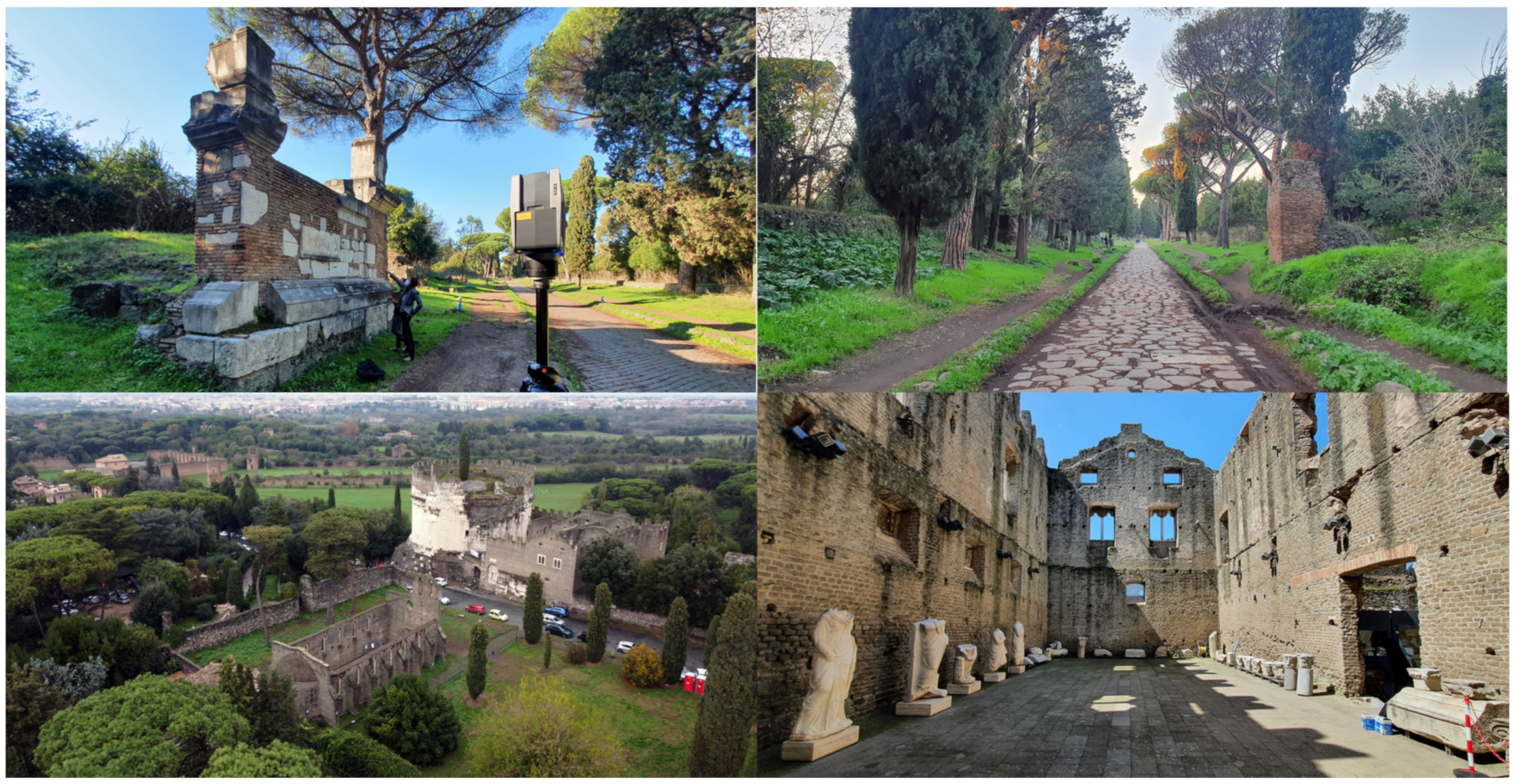
4. The Research Case Studies

4.1. The Appian Way and Its Tangible and Intangible Values: From the Roman Era to Piranesi, Canova, Valadier and Canina

The significant number of publications about the Appian Way traces its history thoroughly. For this paper, only some historical notes will be recalled. This paragraph will be focused on the similarities and differences in the approach of two important architects who dedicated part of their research to the Appian Way: Giovanni Battista Piranesi (1720–1778) and Luigi Canina (1795–1856). Despite the years that separate the two architects, they used similar drawing tools, but with different purposes. According to historical sources, the Appian Way was built by the Roman censor Appius Claudius Caecus around 312 BC. Although it was initially built for military reasons, the road became a vital commercial infrastructure over the century. It crosses four regions (Lazio, Campania, Basilicata, and Puglia) since it connected Rome with Brindisi to guarantee control of the south of Italy.
The construction of the Appian Way proceeded by sectors and many maintenance works have been carried out over the centuries. The pavement of the first mile, which is still partially visible today, was realised with polygonal blocks of mafic lava (Figure 3); some blocks still keep the groove of carts. Roman families built several funerary monuments on the sides of the Appian Way. However, in the Middle Ages, the road lost its funerary function, and many materials were taken from the monuments for other constructions. Many lands on the Appian Way sides became the Church’s property. At the end of the 9th and 11th centuries, some of them were sold by the Church to noble Roman families, such as the Caetani [32].
From the 16th century, Pope Paolo III tried to stop the ‘spoliation’ by creating an Institution of Antiquities to protect the monuments. Over the 18th century, the growing interest in Roman ruins of the ‘Campagna’ brought Italian and foreign architects to start the Grand Tour, together with the study of materials and construction techniques of the road, testified by the work of some of the most influential artists of the time, such as Giovanni Battista Piranesi.
In this great work, Piranesi published many drawings on the Appian Way, starting from the imaginary view of road and monuments, such as ‘Idea delle antiche vie Appia e Ardeatina’ (1750) [33] to the perspective view published in 1756 and collected in the Antichità Romane. The Antichità Romane [34], printed in Rome, is divided into four books. The first book shows the plan of ancient ruins and their topography, together with the marble inscription. The second and the third ones collect the ancient ruins in Rome and the Roman ‘Campagna’ with plans, sections and elevations. The fourth book shows the drawings of ancient bridges, theatres and other monuments. The second and third books collect many engravings about the Appian Way and its monuments. There are different types of drawings: from perspective views of the road to plan, section and elevation of monuments to the drawings regarding the construction techniques of the Appian Way through the representation of the polygonal blocks of mafic lava or the details about the construction techniques of the Cecilia Metella Mausoleum.
There are two engravings on the construction technique of the Appian Way [35]. The first one represents a bird’s eye view of the road realised with polygonal blocks (Figure 4). The road is delimited by giant rectangular stones (crepidines) since they are the same height as the person walking in the middle of the road, the only figure that can help understand the dimensions of the elements in the drawing. Wild vegetation characterised the sides of the Appian Way and only a wall with an arch is revealed in the top-right of the drawings. Other weeds are growing between the pavement and the crepidines of the road. The other engraving could be an inside view of the previous drawing. The engraving shows the stratifications of the different layers of the road. Under the picture, the following description: mortar bed and a layer of pozzolana and stone fragments (A), on top of it polygonal blocks are placed (B), other stones are placed to delimit the road (C), every 30 spans a stone is higher than the other, probably to help people to mount a horse.
The representation of the monuments along the Appian Way, such as the six plates regarding the Mausoleum of Caecilia Metella, is carried out by Piranesi using the common representation techniques: plan, section and elevations, together with perspective views and illustration of the methods used to build the construction and the tools to move the marble blocks of the façade [36].
Other engravings represent views of the Appian Way with a one-point (Figure 4) or two-point perspective. Piranesi used a one-point perspective to exalt the line of the road, to give more depth of field and show the landscape. By doing this, the vanishing point coincides with the end of the visuality of the Appian Way towards the horizon line. The two-point perspective is used to represent the ruins of the ancient monument. In both cases, the representation is not a freeze frame but almost a theatre scene with people playing a specific role [37]. The research on the perspective by Piranesi shows his early apprentice in Giuseppe and Domenico Valeriani’s studio, celebrated artists and scenographers. Piranesi’s perspective often makes an exception in the construction logic of a rigorous drawing by having more vanishing points and anticipating the ‘vertigo shot’ effect in cinema art [38].
However, over the 18th century, despite the growing interest in the Appian Way, it was still an area where many people rented the lands to find objects to be sold in the antique trade. Since people were more interested in Roman findings rather than buildings, monuments were often demolished.
After Canova and Valadier, Luigi Canina, Commissioner of the Antiquities for the Papal Government in 1839, carried out the first great restoration works of the Appian Way between 1851 and 1855 from the IV to the XI mile. Canina arrived in Rome around 1818 to deepen his knowledge of roman architecture. He restored the monuments and created spectacular architectural walls with findings already used by Canova and Valadier. He defined the borders of what was becoming the Appian Way Archaeological Park by realising the macère, the short walls on the sides of the road, built with the rubbles and stones found during the excavations.
Canina published in Rome two volumes called ‘La prima parte della Via Appia dalla Porta Capena a Boville’ (1853) [39], which show his work of documenting and interpreting the existing buildings through descriptions and drawings. Canina uses different scales and representation tools: territorial plan, Appian Way landscape perspective views and monument plan, sections and elevations. These representations give a synthesis and a general idea to the reader. He chose a vertical layout for the plate and on the top of the page a perspective view of the road with the existing ruins, on the bottom the same perspective view with a reconstruction of the monuments, while in the middle, the section of the road. Sometimes on the sides of the plan, construction details are placed. He chose a horizontal layout for the plate referring to the monuments. Canina made the engravings about hypothetical reconstructions, while his collaborators, Giovanni Montiroli and Pietro Rosa, drew monuments [36].
Canina’s drawings testify to the approach of a 19th-century restoration architect, where the study of antiques proceeds together with hypothesis and reconstruction. He uses a central perspective view for the reconstructions to give a general idea of the Appian Way and its landscape because he should be comparing it with Piranesi. However, the vanishing point does not correspond to the eye level of a possible visitor, but is higher up. This choice is a ruse dictated by the desire to show more of the road and the monuments. It would not have occurred if he had chosen a vanishing point and a horizon line at the level of a person’s eyes. Furthermore, these drawings give Canina a more precise idea than what could have been obtained from the description [39] (p. VIII).
The monuments in the engraving on the plate are represented with particular attention to their state of conservation, with vegetation and ruins. However, they are yet the result of the restoration carried out by the architect. Canina’s studies on classical architecture dated back to his arrival in Rome in 1818 and were solid to allow him to formulate reconstructive hypotheses. However, while the reconstruction hypothesis on monuments is corrected typologically, the need to realise elevations imposes simplifications. The monuments are indeed architectural walls where architectural elements and marble inscriptions have been placed. In his reconstructions, it has been pointed out that Canina does not differentiate between the evidence of the ancient ruins and the architectural elements realised for the restoration. However, the purpose of these drawings was oriented to study the design of the monument rather than finding evidence (Figure 5) [40].
Piranesi and Canina used perspective views as the primary tool for the representation of the Appian Way. Hundreds of years passed between the two architects. Their drawings show how the approach to the study of the Roman ruins changed over the years and the different purposes and visions of the architects, which mirror a different culture. Piranesi’s engravings have more pathos and create imaginary or daily life scenes, using the Appian Way as a dynamic scenic backdrop. The work by Canina is more technical and he investigates the way to represent the ruins and their reconstruction hypothesis. He uses a more standard tool, such as a general plan of the road, and the elevation of the monuments, while the perspective is more static.
In addition to the remarkable archaeological and architectural value of the Appian Way, another relevant aspect is the landscape (Figure 6). The landscape of the Appian Way and the Roman ‘Campagna’ is captured in the beautiful drawings and paintings of the 17–18th century, together with the photographs of the 19th century. Many artists, such as Carlo Labruzzi, depicted the Roman ‘Campagna’ landscape with a great variety of trees. Although the landscape we see today is a little different from the old drawings, it is still a natural heritage to be protected. During the restoration works carried out at the end of the 18th century, elms were planted in the Pontine Marshes. However, pines substituted elms at the end of the 1930s, which still characterised the landscape of the Appian Way [41]. In the 2000s, some studies focused on the natural heritage of the Appian Way [42] and trees were classified and plates were placed on the trunks.

4.2. Castrum Caetani: Cecilia Metella Mausoleum, Palace Caetani and S. Nicola church

At the third mile of the Appian Way stands the monumental complex of the Cecilia Metella Mausoleum and Castrum Caetani [43]. The Appian Way, which crosses a hollow at the level of the Massenzio Complex and S. Sebastiano Basilica, rises at the level of the Castrum Caetani, standing on a hill. The different terrain levels are due to the lava flow of Capo di Bove from the eruption of the Lazio volcano around 260 million years ago. Part of the lava flow is still visible at the underground level of the Caetani Palace. The Romans used the same lava flow to build the pavement of the Appian Way.
The mausoleum is one of the magnificent funerary monuments that characterised the Appian Way, built by noble roman families. Next to simple funerary tombs, such as columbariums on different levels for many corpses, and traditional funerary buildings, monuments sui generis stand out. This is the case of the Cecilia Metella Mausoleum, which refers to the Mausoleum of Augusto; although with different dimensions. The mausoleum was built between 20 and 30 BC and was dedicated to the noblewoman Cecilia Metella, daughter of Q. Metello Cretico and wife of Crasso, as can be seen from the inscription on the marble exterior façade of the monument.
The building stands on a square base and has a cylindrical shape. The circumference is about 28 m in diameter and 28 m in height if considering the merlons on the north-east side, while 24 m from the level of the Appian Way (considering merlons). The merlons attest to the change in the use of the mausoleum during the Middle Ages, which became the central defence tower of the Castrum Caetani (Figure 7).
The Mausoleum of Cecilia Metella was gradually transformed into an agricultural estate. Private or ecclesiastical institutions owned the lands around the monument. Cardinal Benedetto Caetani, who became Pope Bonifacio VIII between 1294 and 1303, made it possible to buy the land for his family. The mausoleum was embedded in the project of building a Castrum Caetani: a fortified village characterised by walls, constructions, the Caetani Palace and S. Nicola church. The complex was built between 1302 and 1303; although some scholars suppose there were previous constructions. The walls created a rectangular fence with small towers and closed a portion of the Appian Way. On the north side of the fence, there was the Cecilia Metella Mausoleum and Caetani Palace. In front of the palace, there was and still is the S. Nicola church. The palace is approximately 28 × 22 m and was built on the northeast side of the mausoleum and has five rooms at the ground level. Only the walls are still standing, while the slabs and roof are missing.
On the first floor, two rooms with a fireplace (one great hall and a second smaller room) and a room with a great balcony on the northeast side. When the complex was restored in the 19th century, Giuseppe Valadier built the wall with findings on the side of the entrance facing the Appian Way [44].
St. Nicola church has one single nave with a semi-circular apsis and a bell tower. Eight buttresses and single lancet windows characterised the exterior longitudinal sides. The marble structure of the single lancet windows as the mullioned windows are the results of the restoration carried out in the 20th century. The space was divided into seven bays by arches resting on tuff (peperino) corbels. The roof is missing. St. Nicola church is an example of gothic architecture and is an unusual building in the Roman architectural heritage. It refers to French and Anjou church models and European Cistercians abbeys.

5. 3D Survey Approach Based on Laser Scanning, Digital Photogrammetry and UAV Data Integration: From Point Clouds to High-Resolution Textured Models

This paragraph presents the 3D survey of St. Nicola Church in Castrum Caetani, the mausoleum of Caecilia Metella, Caetani Palace and the Appian way. The survey of St. Nicola Church was conducted with different sensors to cover all the church geometries and shapes and connect them with the survey of the mausoleum. For this reason, passive (terrestrial photogrammetry, aerial photogrammetry) and active sensors (SLAM) were used. The survey of the mausoleum was performed in a previous campaign using the same sensors. It was georeferenced in a global reference system taking advantage of a topographic network around the building. In particular, a geodetic network was established within the research case study to connect the different survey strategies (terrestrial and aerial photogrammetry and laser scanning) into a unique stable reference system. The geodetic network was measured with a Leica TPS1200 total station (TS), and a final least-squares adjustment provided an average precision of ±1.5 mm.
A static TLS survey was planned to capture the state of the monuments. The registration was performed using a target-based approach using a Faro Focus 3D X130. In addition, 20 targets were measured with the TS with an average precision on targets of about ±2.0 mm and 80 points were measured as Check Points and Ground Control Points for the photogrammetric project. In total, 37 scans acquired were registered with a target-based strategy with an average precision of the targets of ±3.0 mm. Those projects aimed to generate orthophotos of the different surveyed areas and the generation of textured models to be used both for 3D modelling and measured drawings. Differently, the survey of St. Nicola Church was connected to the previous one using some SLAM scans and performing a UAV flight over the two buildings. The sensors employed in this campaign are the ZEB Horizon, regarding the SLAM acquisition, a Canon EOS 5D Mark IV coupled with a 20 mm lens for the terrestrial photogrammetry and a DJI Mini 2 as UAV. Before starting the survey, the church’s walls and surroundings were disseminated with coded and not coded targets for laser and photogrammetry. Each target was measured with all the instruments to ensure a rigid connection between each survey. The architecture has a rectangular shape, whose sides measures, respectively, 16 m and 8.6 m; the highest point of the façade is almost 8 m; the roof is not in place. The survey operations began with the laser acquisition and started from a known point next to the mausoleum. This expedient helps the SLAM algorithm process the raw scan data into a point cloud using a method analogous to the traverse technique used in survey practice, in that a previously known position is used to determine its current position (Figure 8). This method can compound any error introduced, causing the measure position to “drift”. As a good practice, each scan was started and finished at the same point; namely, each loop was closed by re-surveying a known position so that the compounded error could be spread around the loop. Six closed loops were permitted to cover the church and the connection between San Nicola and the mausoleum in less than an hour.
Then, the terrestrial photogrammetric survey started. The photographic campaign comprises 358 images taken with a precise geometry: an external ring covering the outer walls, four stripes inside the church to include the internal walls, and four half-circles corresponding with door jabs. This approach ensures a rigid connection between the inside and outside. Considering that the images were acquired at a maximum distance of 5 m from the building, using the aforementioned full-frame camera equipped with a 20 mm lens permitted to obtain a theoretical GSD (ground sample distance) equal to 1 cm. Lastly, two different UAV flights were performed. The first one followed a regular scheme of parallel stripes with the camera pointing downwards perpendicular to the ground. During the second flight, the cameras were tilted by 45 degrees. The flight followed a circular path pointing at the walls. The geometry of acquisition was designed to cover the architecture and obtain in the images all of the targets, both on the ground and on the vertical walls. According to Italian law, the height of the flights stayed within the limit of 25 m. The photogrammetric project includes 245 images with a resolution of 4.000 × 2250 pixels. This integration permitted reaching the upper part of the walls and improving the quality of the 3D model; in these portions, the GSD calculated for the terrestrial acquisition degrades according to the distance.
Moreover, these images allow one to include the apse’s roof and the top of the walls in the main project. On the other hand, the UAV survey of the Appian Way, of mausoleums and archaeological sites, aimed to record the portions of the buildings unreachable from a terrestrial study. As mentioned before, regarding the overflight of St. Nicola Church, also in this area, the operations are allowed until a maximum height of 25 m. These limits are imposed by law to prevent interference with civil and military flights. In Italy, to obtain information about the restrictions, it is mandatory to check the D-Flight portal (Figure 9). D-Flight is a company belonging to ENAV GROUP. It pursues developing and providing low-altitude air traffic management services for all types of aircraft that fall into the UAV category and any activity connected to them. Thanks to the collaboration with ENAC, the only Authority for technical regulation, certification, supervision and control in the civil aviation sector in Italy, has developed the D-Flight services portal for the management of drones and their use, which makes it available to users: (i) the registration of drones in the Italian database and the assignment of a unique identification code for each of them; (ii) the retrieval of useful information to fly with drones safely and in compliance with current regulations.
As shown, the two objects of interest fall inside an orange area in the shape of a rectangle that itself contains a red rectangle. These zones have the same orientation as Ciampino Airport’s take-off and landing runways. In the red zone, the flight is prohibited to protect the aeroplanes while approaching and leaving the airport. Instead, the flight is allowed in the orange zone until a maximum height of 25 m. The yellow buffer means that the proper height reaches an altitude of 45 m. The survey of the Appian Way carried out later, was performed using a different UAV, namely the DJI Mini 3 PRO, which is an improved version of the DJI Mini 2. The DJI Mini’s latest version brings a series of updated and new features that make it the optimal device to be used in this situation. The weight of the two drones is the same, precisely 249 g; in Italy, there are ad hoc and more permissive laws if the weight of a UAV, including the payload, is lower than 250 g. The Appian Way area is in the A1 category (EASA). Accordingly, the Appian Way Archaeological Park authorised the flight and the operational restrictions followed to avoid flying over uninvolved people and assemblies of people.
The updated features regard the drone’s design, the sensors, the anti-collision system, and the battery life, meaning longer flights and more photos acquired. Thanks to the use of the DJI Mavic mini 3 Pro, the drone survey benefited from:
(1) The three-way obstacle detection: DJI Mini 3 Pro features dual front, rear and bottom sensors. Thanks to obstacle recognition, it was possible to increase the detection range, increasing flight safety between the various vertical elements, such as trees and street furniture, which prevent a traditional classic flight (Figure 10). The updated APAS 4.0 system (advanced pilot assistance system) has made it possible to take advantage of intelligent functions. DJI drones have single-shot, multi-shot, AEB, and time-lapse cameras, but there are also DJI drone models, such as the DJI Mavic Pro and DJI Spark that have new camera features, such as Pano mode and HDR Shot. In total, DJI drones offer six modes: (1) Single, (2) Multiple, (3) AEB, (4) HDR, (5) Timed Shot and (6) Pano. Methods 3, 4, and 5 are how the Castrum Caetani survey was tackled (St. Nicola Church, Mausoleum of Caecilia Metella and Caetani Palace). In particular, mode 5 (timed shot) made it possible to select time intervals between individual shots, automating image recovery. The minimum selectable interval between shots is 2 s for JPEG images and 5 s for RAW. With DJI cameras, a Timed Shot of 2, 3, 5, 7, 10, 15, 20, 30, and 60 s can be selected between the individual automatic shots. For the surveys of the Appian Way (IV mile) 3 and 5-timed shot options were used to allow a quick acquisition and position the drone appropriately concerning the subject to be filmed. Unfortunately, APAS 4.0 is not available while recording 4K/48fps, 4K/50fps, 4K/60fps, 2.7K/48fps, 2.7K/50fps, 2.7K/60fps, and 1080p/120fps video.
(2) Improved camera compared to previous versions: Despite the Mini format and low weight, the quadcopter integrates a quality camera with a large sensor. In particular, the 48-megapixel CMOS in 1/1.3” format, larger than the previous models, is coupled to an f/1.7 lens with an equivalent focal length of about 24 mm. For the survey of the mausoleums, the DJI Mavic Mini 3 Pro was preferred to previous versions because the quality of the shots is very high and the QuadBayer sensor is exploited to the fullest to expand the dynamic range (Table 1 and Figure 11). Moreover, the sensor offers access to the 4K/60p format. It has been found that if you choose to shoot in HDR or by activating the Active Track function, it is necessary to settle for 30 frames per second in 4K. The videos can be recorded in MP4 in MOV, with H.264 or H.265 codec and using the D-Cinelike profile to have more room for manoeuvring in post-production. Furthermore, the new version of the gimbal has made it possible to vary the inclination of the camera and photograph elements not detectable by previous versions, such as the DJI Mavic Mini 2. Thanks to the rotation on the camera’s vertical axis, reaching 90 degrees downwards and 60 degrees up, it was possible to photograph under arches, vaults and various architectural and structural elements from the bottom up, expanding the coverage of the photogrammetric survey with multiple angles.
(3) Battery life increased: DJI Mini 3 also offers a standard battery of 34 min of autonomy and an optional higher-capacity battery to go up to 47 min of autonomy. Unfortunately, using the increased battery raises the take-off weight above the 250 g limit, thus dropping DJI Mini 3 Pro into the segment of drones with more limitations and requiring a license. For the EASA regulation, the drone, weighing less than 250 g, but being equipped with a camera, does not require a pilot certificate to fly in the conditions of the Open A1 sub-category, but requires registration on the national D-Flight portal. As mentioned, in the presence of Plus batteries, the weight exceeds the 250 g limit and the drone falls under the rules of the Open A3 sub-category, requiring a license and a minimum distance of 150 m from urban agglomerations and the absolute ban on flying above or near people.
(4) New remote control: Thanks to the new remote control, DJI RC, it was possible to take advantage of the integrated 5.5 inch touchscreen with integrated DJI Fly app, high battery life and high brightness screen. This improvement has made it possible to avoid using the mobile phone and increase flight times, also avoiding depending on the latter’s battery. The connection to the drone was stable in driving and image transmission. The remote control also integrates a MicroSD slot for local recording of drone footage. Having the app already integrated has eliminated some of the ‘troubles’ afflicting remote controls that instead require a smartphone, facilitating a rapid survey and preventing the area from being closed for flight operations.
The elaboration started with the laser data. The photogrammetric process was developed using Agisoft Metashape, organising the images in two groups according to the sensor employed. The workflow followed these steps for each group image: alignment of the photos, positioning of the targets to optimise and place the project in the global reference system, using the coordinates coming from the laser campaign. Then, they were merged into a single block and the elaboration continued with the dense matching, the generation of the 3D mesh, and finally, building the high-resolution textured models (Figure 12).
The final 3D models and as-found drawings describe the whole architecture both from a geometrical and a qualitative point of view; the 5 million mesh has an accuracy of 1 mm and the texture gives information about the state of health of the building, highlighting the decay (Figure 13 and Figure 14).

6. Architectural Representation Scales: Digital Model Orientation for Archaeology, VR-AR and Preservation Purposes

UAV Data and Terrestrial Digital Photogrammetry for Augmented Reality: The Appian Way Case Study

The representation of architecture and environment is understood as a tool for analysing existing values of an expressive act. Visual communication has been oriented to different scaled dimensions, including the geometric descriptive foundations of drawing and digital modelling, based on the survey as an instrument of knowledge of the architectural, environmental and urban reality of the case studies in question. Through the integrated use of digital photogrammetry (terrestrial and aerial), and laser scanning, the adopted approach allows us toconver point clouds and meshes into an interactive environment capable of communicating with both AR devices and VR-featured projects, offering a greater level of interactivity and immersion.
The main phases applied are the following:
  • Digital survey (topographic, laser scanning, unique control geodetic network)
  • Terrestrial and aerial photogrammetric survey, post-processing (point clouds and mesh model orientation)
  • 3D drawing and NURBS modelling orientation for HBIM projects
  • Quality check of the model produced (by element)
  • HBIM conversion and data enrichment
  • Common data environment and cloud sharing (BIM-based project shared)
  • Real-time synchronisation between 3D models (NURBS-HBIM projects) and XR development platform
  • 3D Mapping calibration and texture generation
  • Virtual-visual storytelling definition and visual programming language
  • VR and AR outputs, 3D animation and multimedia data production.
Terrestrial and aerial photogrammetric survey, post-processing (point clouds and mesh model orientation): the UAV survey, integrated with terrestrial photogrammetry, was mainly focused on 50 m of the IV mile, regarding the Funerary temple with a columbarium, the Tomb of Tiberio Claudio Secondo and the Elliptical columbarium, witnesses of the different funerary monuments that can be seen along the Appian Way (Figure 15). Among other studies, the geometrical direct survey and drawings of the monuments (I-IV miles) by Italian and international students of the Università degli Studi Roma Tre published in 2017 were particularly interesting for understanding the three tombs at the IV mile [45].
The Funerary temple with columbarium has walls realised with the opus testaceum technique. The square chamber is covered by a barrel vault, partially preserved, plastered on the intrados. Six funerary niches are placed at the bottom of the northeast wall. Vegetation covers the extrados of the monument. Many stones were replaced, and some walls were made of bricks.
The tomb of Tiberio Claudio Secondo (plate XXI–XXII Canina) is the result of the restoration work carried out by Canina (1851-53), where inscriptions and marble and tuff stones are inserted in a brick wall, which serves as an architectural scene. The wall stands on a base with stones as a moulded pedestal. On the back of the wall, traces of the Roman funerary monument are still visible, covered by vegetation. After Canina, other restorations were carried out, as is visible from the stones, with a bush-hammering finishing that replaced the original ones. Two memorial stones are placed on the top of the wall, where a cocciopesto covering was realised to protect the monument from rainwater. The last restoration was by the Archaeological Superintendency of Rome in 1999.
The brick columbarium with a vault has a square fenced area facing the Appian Way and a square chamber accessible on the back. The chamber has a square plan on the outside, while on the inside, the southwest side has a rounded shape. The walls are made of bricks; some were restored, while on the outside are still visible fragments of plasters. Funerary niches are placed all along the inner walls.
3D drawing and NURBS modelling orientation for HBIM project: The 3D modelling involved the use of dense point clouds and high-resolution textured mesh models from digital photogrammetry (aerial and terrestrial) and laser scanning. For most of the included mausoleums and archaeological remains of the Appian Way, integrated modelling between NURBS mathematical models and textured mesh models was considered. The aim was to maintain high levels of detail (LOD), accuracy and 3D mapping as truthful as possible. High-resolution orthophotos and textures produced by the photogrammetric process avoided using generic textures of materials and allowed authors to obtain a high realism. NURBS modelling for archaeological and architectural elements was fundamental. Thanks to the analysis and interpretation of the data produced by the 3D survey and the deep analysis of the historical representation and archives, it was possible to define 3D drawings capable of going beyond the textured mesh models. The interpretation of 3D survey data and the semantic subdivision by elements of every single artefact has allowed for the identification of the elements’ main architectural and structural discontinuities, identifying their volumetric size, and subsequently drawing and modelling every single component. In this context, representation is understood in the widest meaning of the term as both the expressive and cognitive aspects of the formal structure. Drawing as a graphic, infographic and multimedia language has been declined in 2D and 3D dimensions, becoming a vital tool capable of governing the paradigms of the morphological and typological complexity of the case studies, analysing existing values and enhancing visual communication at different scalar dimensions (Figure 16). Finally, applying NURBS algorithms and specific export schemes has made it possible to model and import geometric models in Autodesk Revit and proceed with the next phase of parameterisation in BIM and building archaeology.
Quality check of the model produced (by element): The verification in geometric terms of the model concerning the data coming from the 3D survey envisaged the application of an automatic verification system (AVS) capable of communicating the value of the standard deviation between point clouds and the model. Starting from the assumption that the geometric reliability of each model derives not only from the precision of the survey but also from the pre-modelling interpretation phase of every single element, this study, in terms of accuracy, has reached very faithful values concerning the pre-established scale of representation. Each element was returned with a grade of accuracy (GOA) of about 4/5 mm, starting from an error value (m) of about 1/2 mm concerning the precision of the photogrammetric survey. The reliability in terms of accuracy was transmitted within the BIM project through the development of specific HBIM parameters [46]. Customising every element’s BIM parameters involved developing new HBIM parameters. The identification of each single data used and the relative GOA achieved were specified in the BIM properties windows. The GOA value was based on the standard deviation (or σ). It is a measure of how dispersed the point cloud is concerning the model. A low standard deviation means point clouds are clustered around the model, and a high standard deviation indicates point clouds are more spread out (Figure 17).
HBIM generation and data enrichment (connection of information to each BIM object): textured mesh models from digital photogrammetry do not allow professionals involved in the restoration, protection and preservation of mausoleums and archaeological remains to identify the various components. The parameterisation of geometric entities, such as primitives, surfaces, polysurfaces and solids is crucial for recognising these entities in the BIM environment. As known, BIM applications were born to manage new buildings in architectural, structural and MEP. The development of HBIM projects consequently required a flow able to interoperate between different modelling techniques to obtain an adequate interpretation and parameterisation of the NURBS models. The transformation process consequently excluded the (non-convertible) meshes and envisaged a phase of conversion of the digital models using the DWG format and 2007 Solids export scheme. Once the NURBS models from a scan-to-BIM process had been converted, it was then possible to recognise the entities imported into Autodesk Revit and proceed with the semi-automatic recognition and transformation of the various archaeological, architectural and structural elements into BIM objects.
Once the BIM objects were obtained, it was possible to enable the information mapping and computing functions. The latter, considered the main functions that distinguish BIM projects from mesh and NURBS models, had allowed the connection of information of a physical, mechanical, and historical nature and the drafting of abacuses capable of telling the current state of every single artefact detected. Figure 18 shows the process for the conversion of each area from the NURBS surface to the HBIM object for the material analysis and the area quantification (Figure 18).
Common data environment and cloud sharing (BIM-based project shared): In Italy, the BIM decree DM 56 of 12/1/2017 in articles 3, 4 and 5 explicitly provides for open formats and a data sharing environment to ensure interoperability. Furthermore, the UNI 113,377 Regulation, a fundamental reference in Italy, in its parts 5 and 6, defines the data sharing environment, called ACDat, corresponding to the English CDE (common data environment). The characteristics that the ACDat should have are related to accessibility based on rules, traceability of revisions, comprehensive support of formats and processing, access to the platform and use of open protocols, conservation and updating of data, confidentiality and guarantee of safety. BIM means collaborating and sharing any aspect of the project, from the initial conceptual stages to implementation, among all the professional figures involved in the process. The advantages are many: access to a multi-platform from a web browser without constraints on the operating system, access anywhere via an Internet connection, sharing identification in full compliance with procedures and safety standards, and continuous improvements and updates are detected immediately upon access.
The process applied to the various case studies inevitably implied the cooperation of different professional figures. The need to reach the multiple professionals involved in the protection, restoration and preservation process has led to an investigation into the primary forms of cloud sharing of BIM models applied to new buildings. The main BIM applications, such as Autodesk Revit and Graphisoft Archicad, offer various applications on the market.
The main modes are:
  • BIM 360 Docs: Environment, common to all the other modules, is where data and project sharing and collaboration occur.
  • BIM 360 Design: Design: Autodesk Collaboration for Revit allows one to work directly in Revit and collaborate simultaneously in the cloud.
  • BIM 360 Glue: Interference checking and site planning.
  • BIM 360 Build: Real construction site.
  • BIM 360 Ops: Management and maintenance of the built work.
In particular, to facilitate the protection process of both the ancient Appian Way and the mausoleum of Caecilia Metella and Caetani Castrum, BIM 360 Docs proved to be an adequate CDE capable of responding to the needs of the project team. Data sharing was simulated and viewable through an interactive interface that displays models and associated information in a single solution.
Real-time synchronisation between 3D models (NURBS-HBIM projects) and XR development platform: Recent developments in the XR field have made it possible to access platforms capable of developing interactive VR and AR environments without opting for advanced computer skills. As described later, the VPL is a tool you can switch between static models and interactive virtual objects (IVOs). Before creating digital objects capable of responding to user inputs, it was crucial to lay the foundations for an interactive digital representation capable of synchronising in real-time with the XR development phase. In this context, thanks to the introduction on the market of platforms, such as Unity, Twinmotion and Unreal Engine and related add-ins, it was possible to proceed with putting digital models (Mesh, NURBS and BIM) on the same level of development with the preparation of the scene ready to be implemented, customised and oriented towards VR and AR.
3D mapping calibration and texture generation: Synchronising the models with the XR development environment has allowed authors to optimise the 3D mapping phase. BIM models require the association of materials to each object. The wall stratigraphy’s editing and the typology definition are decisive for the parametric and bidirectional information–object association. The materials in Revit also allow you to associate information of a physical and mechanical nature directly and to expand each single BIM object with external content and resources. On the other hand, the Mesh and NURBS models can take advantage of high-resolution textures and orthophotos from digital photogrammetry (terrestrial and aerial). Thanks to the real-time synchronisation, it was, therefore, possible to transfer the richness of the digital models into the XR development application without opting for the second phase of remodelling and 3D mapping.
Virtual-visual storytelling definition and visual programming language: Once the scene was prepared, trying to represent and communicate the tangible values of every single element detected (materials, geometries), it was possible to define how the VR and AR environment was, in turn, oriented towards the end user (professional or tourist). Thanks to the VPL, it was possible to ‘give life’ to digital models, breaking them down into IVOs capable of communicating intangible values and specific information where, in on-site and visiting places, it is not possible to use or reach. Consequently, the collection and definition of ‘what ‘and ‘how’ to share through an interactive representation resulted in a necessary step for the subsequent planning phase associated with the IVOs.
VR and AR outputs, 3D animation and multimedia data production: The representation process ended with a step able to communicate the case studies as innovatively and interactively as possible, trying to reach different types of users on-site and remotely. In particular, Twinmotion and Unreal Engine have created a single environment capable of orienting itself according to the kind of use and device. As known, the main difference between AR and VR lies in the method of use and the device used. AR increases the informative value of the scene by framing the object of interest with the device’s camera. At the same time, VR creates a virtual environment capable of expanding the paradigms of interactivity and immersion through devices such as the Oculus Rift and Quest. Both methods have been implemented and investigated to provide a multi-scalar experience at the various levels of detail required (Figure 19). The next paragraph describes the results obtained, from a description of the VVS to the VR–AR experiences developed for the three studies of this research.

7. Design the Narrative Structure: Towards the Virtual-Visual Storytelling

In recent years, with the advent of social media, the various brands have begun to tell each other more and more often, through short moments, short stories characterised by a strong visual component. In the same way, users and tourists who visit a museum or archaeological site give life to their stories by publishing photos and short stories. These modalities have also spread among public bodies, archaeological sites and museums, trying to tell stories and events through images and multimedia files, such as video and audio. This process is nowadays defined with the term visual storytelling, which indicates the planning and organising of the “narration of a story” that uses images as an expressive means. These are multimedia contributions that do not remain ends in themselves, but have the purpose of creating and narrating a story in which the people who use them can immerse themselves, trying to convey emotions and involve users with characters and paths in which people can identify.
Consequently, visual storytelling can be considered a fundamental strategic asset for marketing and communication strategies, where the full value of representation through images is exploited to involve the public deeper to guarantee an immersive experience.
In the book “The Power of Visual Storytelling: How to Use Visuals, Videos, and Social Media to Market Your Brand”, the authors Ekaterina Walter and Jessica Gioglio [47] report that the human brain can process images 60,000 times faster than text. Visual contents work precisely because they are immediate, exciting, evocative, engaging and capable of moving the deepest part of the human being.
The immersive experience is the basis of visual storytelling: the combination of images and text can arouse attention, reinforcing the message and prolonging the memory of the experience itself. Consequently, visual storytelling requires the knowledge and application of specific operating rules to create visual stories.
In particular, five basic rules must be followed to achieve storytelling that can communicate appropriately:
-
Respecting the ‘5 W’ of journalism: linear and engaging story able to clarify who is the protagonist of the story, what happens in the story, where and when the story or period represented takes place, and finally, explicitly address the reason for which the story was created, explaining in the best possible way what are the factors that motivate the succession of the events of the narrated story;
-
Showing and not saying: indirectly communicate what you want to express, through the narration of events, ensuring that the target directly understands the message, thus reinforcing its authenticity and persuasive effectiveness;
-
Being original in narrating: the conservation of an overall organic nature of the narration to make it intelligible and credible for one’s reference audience;
-
Space for imagination and details: the attention and interest of the reference audience differentiate the story, characterising it as unique and inimitable.
In this context, the authors investigate the added value of the latest generation of representation techniques, where the paradigms of interactivity and immersion are the key elements for an all-encompassing virtual experience. The best way to communicate the details of a narrative is to immerse (more or less ideally) your target in a sensory experience: the distinctive elements of the story must emerge from perception through the various senses, in particular, sight, hearing and touch. For these reasons, visual storytelling can be transposed and oriented to the virtual, where the latest technological updates in the field of VR allow you to immerse yourself in a new experience, passing from a passive story to an engaging, interactive moment made up of interactive virtual objects (IVO) that respond to visitor input. Finally, another aspect not to be forgotten is that of the sources: to support the truthfulness, and, therefore, the credibility of the story narrated, it is advisable to use qualified and objective sources as much as possible that can confirm the assertions and promises made in the narration.
There are currently several applications on the market that can support the activity of a storyteller, such as Shorthand, Steller, Thinglink and many others. In most cases, the possible outputs of those applications are edited images, videos and audio. In the best circumstances, finding multiple multimedia files is possible. This study investigated the forms of programming, such as the VPL and recent XR platform developments to distinguish the contribution and research aimed at improving accessibility to knowledge and to the Appian Way site itself and its treasures, such as mausoleums, archaeological remains, parks and historic buildings attributable to the Roman era. Thanks to introducing an IT language based on the VPL, it has been possible to transform digital models into immersive experiences. On the other hand, thanks to the use of drones, it has been possible to inherit geometries that are difficult to represent and complete the modelling of complex scenarios, such as the Appian Way and the most important historical artefacts, which in a capillary way characterise not only the road asset but extend to the surrounding landscape. For this reason, it was necessary to transfer this historical, cultural and geometric richness into forms of representation capable of giving life to objects and information.
The VVS was based on editing content and behaviours related to the IVOs developed to make the experience as realistic as possible and rich in content and analysis. The visitor experience has been designed both in the first and third person to satisfy different types of users, pass from the expert user able to interact with the VR headset and less expert users who are content to interact with available mobile (tablet and mobile) or PC. In this way, it was possible to investigate the forms of interaction and the proxemics established between the user and the IVO.
The UAV survey, integrated with terrestrial photogrammetry, of the Cecilia Metella complex was mainly focused on understanding the different construction phases of the complex, especially of the Caetani Palace. The orthomosaics derived from the UAV survey were the basis for the building archaeology analysis. The level of the first floor is visible from the beam imprints and the signs of the floor on the walls, which correspond to the level of the doors and windows. Then, it needs to be made clear how the first floor’s roof or slab looked since big beam imprints are visible at the level of the square windows above the mullion windows. However, smaller beam imprints, which broke the walls, are visible under the level of the square windows. The small marble corbels, at 2.50 m ca from the first-floor level, at a steady pace on each wall of the rooms, were probably used to hang curtains, a common use in the Middle Ages. Aerial photogrammetry allowed intercepting all the construction elements in the upper part of the St. Nicola Church. Thanks to the implementation of an HBIM model, it was possible to outline a process capable of communicating specific information to the professionals involved in the building preservation process and guaranteeing a VVS to the visitors on-site and remotely. The HBIM has been obtained thanks to a deep analysis of historical archives, drawings and possible hypotheses of historical reconstructions of Leporini (1958). Figure 20 shows the restitutive hypothesis of both the interior and the exterior.
The church was consecrated on May 12, 1303 and dedicated to St Nicola di Bari. It is located inside the castrum, overlooking the palace. The building is a single hall with a semi-circular apse at the back and has a half-preserved bell gable on the façade, with two bells opening. A portal marks the entrance to the Via Appia Antica with a simple marble frame above an oculus. The masonry of the church is in tuff blocks, originally covered with plaster, of which some traces remain. The exterior is marked by eight buttresses on each side, which alternate with single-lancet windows, with marble frames partially restored at the beginning of the twentieth century. Six windows punctuate the interior on each side, between which are twelve peperino shelves decorated with chalices with leaves, above which the ribs of the pointed arches were set, dividing the space into seven bays. The imprints of the roof of the wooden gabled type, supported by the system of arches, remain on the internal elevation of the main façade. No traces of the pavement have been preserved. The light penetrated through the windows and helped expand the space in the width direction. The church, refined, albeit in the rigour of the style, which refers to the European environment of the Cistercian abbeys, is the only example of Cistercian Gothic architecture in Rome. When he was a cardinal, the prolonged presence in Paris of Boniface VII must have conditioned the architectural choices adopted for constructing this building. The church remained private until 1859 when the Papal States bought it from Mr. Jannetti to the Caetani Church and the surrounding area; from 1870 it became part of the state property. Today, the complex, recently restored, is under the jurisdiction of the Ministry of Cultural Heritage and Activities, Archaeological Superintendency of Rome and is open to the public. The HBIM model includes the state of the building and its material analysis. On the other hand, the VVS narrates the history of the heritage building and shows its historical reconstruction (Figure 21 and Figure 22).

8. Conclusions

The definition and application of digital survey and representation methods, such as the scan-to-BIM process, aerial and terrestrial photogrammetry, make it possible to lay the foundations for the creation of new digital worlds where the paradigm of interactivity can be investigated, analysed and applied in different disciplinary fields, from archaeology and restoration to new immersive forms of virtual museums. Thanks to aerial photogrammetry, it was possible to represent complex scenarios where portions of buildings or archaeological sites were difficult to detect. Integrating aerial photogrammetry has also made it possible to decline the representation at different scales, from archaeological and architectural to environmental.
In this context, the digital models that support different phases of the building life cycle have been oriented towards HBIM, VR and AR environments and tools where the information component becomes one of the added values. These environments’ semantic enrichment and interactivity determine the experience and the proxemics created between the user and the content. For that reason, this study outlines a method capable of optimising the use of digital models for the definition of virtual-visual storytelling (VVS), passing from static forms of representation to interactive forms capable of communicating tangible and intangible values of the built heritage.
The osmosis between digital environments and information consequently allows one to define new experiences where the user (professional or virtual tourist) can immerse himself and actively discover new digital worlds made up of interactive virtual objects (IVO) able to come to life and respond to user inputs. In this way, the representation becomes the driving force for transmitting knowledge, favouring the definition of educational experiences inherent in representing architecture, archaeology and the environment. In addition, the process proposes a digital transformation of reality into tools for analysing existing values through expressive acts and new forms of visual communication at different scalar dimensions. By studying the scientific foundations of drawing, 3D modelling and virtual representation, it was possible to transmit the historical and cultural values of three sites that have characterised the Appian Way since Roman times. Archival research, the study of the representation and the works of past masters, such as Canina, Canova, and Piranesi, have made it possible to understand the architectural, urban and environmental reality, the procedures and techniques of construction, restoration and graphic, morphological and thematic restitution.
On the other hand, information technology in recent years has become much more personal because we have moved from a desktop computer to have a complete product in the palm of our hand and with minimal dimensions. Desktop computing was mostly about information processing, and smartphones were mostly about communication. The next computing era could be ‘experiential’ and ‘interactive’. In this context, it could be helpful to investigate and understand the main differences between AR and VR future developments and their applications. Currently, AR can be added to physical reality through devices such as a smartphone, a tablet and a computer. On the other hand, VR is a total experience, an isolation of physical reality in a mask, which, when worn, cuts off communication with reality to enter a 360-degree virtual world. For those main differences, the most frequently asked question is whether AR and VR become real customisable technology platforms rather than simple accessories to be used from time to time. It is for these reasons future developments will be oriented to investigate how these two forms of representation can merge and create osmosis oriented to expand heterogeneous contents, becoming a real platform that can be customised and used in museum reality as an integrative tool and a useful tool to create and disseminate knowledge starting from one’s own home, school or work environment.
In conclusion, drawing, as a graphic infographic language, and architectural representation were investigated and transferred to digital, applied to the design process of a VVS, starting from the formation of the idea to its executive definition. The respect and application of specific rules were essential for designing and representing a VVS capable of encompassing historical and cultural values, moving from the tangible aspects of reality to forms of interactive representation capable of communicating intangible values from ancient Rome.

Author Contributions

Conceptualization, F.B.; methodology, F.B. and C.S.; software, F.B and A.M.; validation, F.B.; formal analysis, S.R. and C.S.; investigation, S.R.; resources, S.R. and C.S.; data curation, F.B.; writing—original draft preparation, F.B. and C.S.; writing—review and editing, F.B. and C.S.; visualization, F.B. and C.S.; supervision, F.B.; project administration, F.B. All authors have read and agreed to the published version of the manuscript.

Funding

This research received no external funding.

Data Availability Statement

Not applicable.

Conflicts of Interest

The authors declare no conflict of interest.

References

  1. Docci, M.; Maestri, D. Manuale di Rilevamento Architettonico e Urbano; GLF Editori Laterza: Bari, Italy, 2020. [Google Scholar]
  2. Fiz, J.I.; Martín, P.M.; Cuesta, R.; Subías, E.; Codina, D.; Cartes, A. Examples and Results of Aerial Photogrammetry in Archeology with UAV: Geometric Documentation, High Resolution Multispectral Analysis, Models and 3D Printing. Drones 2022, 6, 59. [Google Scholar] [CrossRef]
  3. Bianchini, C.; Ippolito, A.; Bartolomei, C. The surveying and representation process applied to architecture: Non-contact methods for the documentation of cultural heritage. In Handbook of Research on Emerging Digital Tools for Architectural Surveying, Modeling, and Representation; IGI Global: Hershey, PA, USA, 2015; pp. 44–93. [Google Scholar]
  4. Brusaporci, S. Handbook of Research on Emerging Digital Tools for Architectural Surveying, Modeling, and Representation; IGI Global: Hershey, PA, USA, 2015. [Google Scholar]
  5. Muchiri, G.N.; Kimathi, S. A review of applications and potential applications of UAV. In Proceedings of the Sustainable Research and Innovation Conference, Pretoria, South Africa, 20–24 June 2022; pp. 280–283. [Google Scholar]
  6. Shadiev, R.; Yi, S. A systematic review of UAV applications to education. Interact. Learn. Environ. 2022, 1–30. [Google Scholar] [CrossRef]
  7. Aabid, A.; Parveez, B.; Parveen, N.; Khan, S.A.; Zayan, J.M.; Shabbir, O. Reviews on Design and Development of Unmanned Aerial Vehicle (Drone) for Different Applications. J. Mech. Eng. Res. Dev. 2022, 2022 45, 53–69. [Google Scholar]
  8. Pepe, M.; Alfio, V.S.; Costantino, D. UAV Platforms and the SfM-MVS Approach in the 3D Surveys and Modelling: A Review in the Cultural Heritage Field. Appl. Sci. 2022, 12, 12886. [Google Scholar] [CrossRef]
  9. Barba, S.; Limongello, M.; Parrinello, S.; Dell’Amico, A.; di Filippo, A. D-SITE. Drones. Systems of Information on Cultural Heritage for A Spatial and Social Investigation; Pavia University Press: Pavia, Italy, 2020; Volume 1. [Google Scholar]
  10. Ulvi, A. Using UAV Photogrammetric Technique for Monitoring, Change Detection, and Analysis of Archeological Excavation Sites. J. Comput. Cult. Herit. 2022, 15, 1–19. [Google Scholar] [CrossRef]
  11. Whitford, B.; Boyadzhiev, K.; Ivanov, M.; Tyufekchiev, K.; Boyadzhiev, Y. A Photogrammetry-Assisted Methodology for the Documentation of Complex Stratigraphic Relationships. Adv. Archaeol. Pr. 2022, 10, 428–439. [Google Scholar] [CrossRef]
  12. Bevilacqua, M.G.; Russo, M.; Giordano, A.; Spallone, R. 3D Reconstruction, Digital Twinning, and Virtual Reality: Architectural Heritage Applications. In Proceedings of the 2022 IEEE Conference on Virtual Reality and 3D User Interfaces Abstracts and Workshops (VRW), Christchurch, New Zealand, 12–16 March 2022; pp. 92–96. [Google Scholar]
  13. Attenni, M.; Bianchini, C.; Griffo, M.; Senatore, L.J. HBIM Meta-Modelling: 50 (and More) Shades of Grey. ISPRS Int. J. Geo-Inf. 2022, 11, 468. [Google Scholar] [CrossRef]
  14. Yang, X.; Grussenmeyer, P.; Koehl, M.; Macher, H.; Murtiyoso, A.; Landes, T. Review of built heritage modelling: Integration of HBIM and other information techniques. J. Cult. Herit. 2020, 46, 350–360. [Google Scholar] [CrossRef]
  15. Russo, M. AR in the Architecture Domain: State of the Art. Appl. Sci. 2021, 15, 6800. [Google Scholar] [CrossRef]
  16. Shariq, M.H.; Hughes, B.R. Revolutionising building inspection techniques to meet large-scale energy demands: A review of the state-of-the-art. Renew. Sustain. Energy Rev. 2020, 130, 109979. [Google Scholar] [CrossRef]
  17. Colomina, I.; Molina, P. Unmanned aerial systems for photogrammetry and remote sensing: A review. ISPRS J. Photogramm. Remote Sens. 2014, 92, 79–97. [Google Scholar] [CrossRef] [Green Version]
  18. Rakha, T.; Gorodetsky, A. Review of Unmanned Aerial System (UAS) applications in the built environment: Towards automated building inspection procedures using drones. Autom. Constr. 2018, 93, 252–264. [Google Scholar] [CrossRef]
  19. Kangunde, V.; Jamisola, R.S.; Theophilus, E.K. A review on drones controlled in real-time. Int. J. Dyn. Control 2021, 9, 1832–1846. [Google Scholar] [CrossRef] [PubMed]
  20. Russo, M. Imaging for archaeology: An instrument of reading and interpretation complex architecture. In Redibujando el Futuro de la Expresión Gráfica Aplicada a la Edificación/Redrawing the Future of Graphic Expression Applied; Suàrez, R.P., Dorta, N.M., Eds.; Artes Graficas: Valencia, Spain, 2021; pp. 203–219. [Google Scholar]
  21. Diara, F.; Rinaudo, F. ARK-BIM: Open-Source Cloud-Based HBIM Platform for Archaeology. Appl. Sci. 2021, 11, 8770. [Google Scholar] [CrossRef]
  22. Noor, N.M.; Abdullah, A.; Hashim, M. Remote sensing UAV/drones and its applications for urban areas: A review. In IOP Conference Series: Earth and Environmental Science; IOP Publishing: Bristol, UK, 2018; Volume 169. [Google Scholar]
  23. Giovannini, E.C.; Lo Turco, M.; Tomalini, A. Digital practices to enhance intangible cultural heritage. Int. Arch. Photogramm. Remote Sens. Spat. Inf. Sci 2021, 46, 273–278. [Google Scholar] [CrossRef]
  24. Orihuela, J.L. eCommunication: The 10 paradigms of media in the digital age. In Towards New Media Paradigms. Content, Producers, Organisations and Audiences. II COST A20 International Conference Proceedings; Salaverría, R., Sádaba, C., Eds.; EUNATE: Pamplona, Spain, 2004; pp. 129–135. [Google Scholar]
  25. Hassanalian, M.; Abdelkefi, A. Classifications, applications, and design challenges of drones: A review. Prog. Aerosp. Sci. 2017, 91, 99–131. [Google Scholar] [CrossRef]
  26. Masiello, L.; Oreni, D.; Severi, M. Un modello HBIM per la catalogazione dei restauri e la gestione degli interventi: La Rocca estense di San Martino in Rio/A HBIM Model to Catalogue the Restorations and to Manage the Interventions: The Rocca Estense of San Martino in Rio. In Connettere. Un disegno per annodare e tessere. Linguaggi Distan- ze Tecnologie. Atti del 42° Convegno Internazionale dei Docenti delle Discipline della Rappresentazione/Connecting. Drawing for weaving relationship. Languages Distances Technologies. Proceedings of the 42nd International Conference of Representation Disciplines Teachers; Arena, A., Arena, M., Mediati, D., Raffa, P., Eds.; Franco Angeli: Milano, Italy, 2021; pp. 2455–2470. [Google Scholar]
  27. Lo Turco, M.; Giovannini, E.C.; Tomalini, A. Parametric and Visual Programming BIM Applied to Museums, Linking Container and Content. ISPRS Int. J. Geo-Inf. 2022, 11, 411. [Google Scholar] [CrossRef]
  28. Cocchiarella, L. BIM: Dimensions of space, thought, and education. Disegnarecon 2016, 9, 3.1–3.5. [Google Scholar]
  29. Buratti, G.; Costa, F.; Rossi, M. La gamifications incontra il BIM. Pudcad: Progressi nello sviluppo di un gioco per l’insegnamento dei principi dell’universal design/Gamifications meets BIM. Pudcad: Advances in development of a games to teach universal design principles. In 3D Modeling & BIM. Mìmodelli e Soluzioni per la Digitalizzazione; DEI srl: Ivrea, Italy, 2019; pp. 148–165. [Google Scholar]
  30. Thompson, G. International Competitiveness and Globalization: Framework for Analysis, Connections and Critiques. In International Competitiveness and Environmental Policies; Barker, T., Köhler, J., Eds.; Edward Elgar Publishing: Cheltenham, UK, 1998; pp. 13–31. [Google Scholar]
  31. Giordano, A.; Russo, M.; Spallone, R. Representation Challenges: Searching for New Frontiers of AR and AI Research. In Representation Challenges. New Frontiers of AR and AI Research for Cultural Heritage and Innovative Design; Giordano, A., Russo, M., Spallone, R., Eds.; Franco Angeli: Milano, Italy, 2022; pp. 9–18. [Google Scholar]
  32. Mazzotta, B. La via Appia antica: Da asse stradale a parco archeologico. In Patrimonium Appiae. Depositi Emersi; Paolillo, F., Pontisso, M., Roascio, S., Eds.; SAP Società Archeologica: Quingentole (Mn), Italy, 2022; pp. 59–75. [Google Scholar]
  33. Piranesi, G. Opere Varie di Architettura Prospettive Grotteschi Antichità Sul Gusto Degli Antichi Romani; Si Vendono Presso l’Autore: Roma, Italy, 1750. [Google Scholar]
  34. Piranesi, G. Le Antichità Romane; Stamperia di Angelo Rotilj: Roma, Italy, 1756. [Google Scholar]
  35. Bevilacqua, M. Piranesi e la Via Appia. In Oltre Roma. Nei Colli Albani e Prenestini al tempo del Grand Tour; Fratarcangeli, M., Silvagni, I., Eds.; De Luca: Roma, Italy, 2012; pp. 152–162. [Google Scholar]
  36. Segarra Lagunes, M.M. (Ed.) La via Appia descritta, disegnata, restaurata. In Via Appia. I Disegni Degli Architetti; Electa: Milano, Italy, 2017; pp. 35–67. [Google Scholar]
  37. Panza, P. Piranesi e la veduta performativa. Studi Di Estet. 2021, 3, 31–41. [Google Scholar]
  38. Menconero, S. Il superamento del limite nell’arte di Piranesi. Diségno 2021, 9, 121–132. [Google Scholar]
  39. Canina, L. La prima parte della Via Appia dalla Porta Capena a Boville: Monumenti; G. A. Bertinelli: Roma, Italy, 1853. [Google Scholar]
  40. Novello, G.; Bocconcino, M.M. Sulle facoltà del disegno: Potenziale informativo ed espressività nelle opere dedicate agli studi storico-archeologici dell’architetto Luigi Canina. Disegnare Con. 2017, 10, E2.1–E2.14. [Google Scholar]
  41. Quilici, S. Il parco archeologico dell’Appia Antica: Un paesaggio pluristratificato. In Patrimonium Appiae. Depositi Emersi; Paolillo, F., Pontisso, M., Roascio, S., Eds.; SAP Società Archeologica: Quingentole (Mn), Italy, 2022; pp. 91–101. [Google Scholar]
  42. Parco Regionale dell’Appia Antica, La flora. 2002. Available online: https://www.parcoappiaantica.it/wp-content/uploads/2021/04/13.LaFlora.pdf (accessed on 22 November 2022).
  43. Paris, R. Via Appia. Il mausoleo di Cecilia Metella e il Castrum Caetani; Electa: Milano, Italy, 2000. [Google Scholar]
  44. Filetici, M.G.; Paris, R. L’Appia: Progetti e realizzazioni. In Via Appia. I Disegni Degli Architetti; Segarra Lagunes, M.M., Ed.; Electa: Milano, Italy, 2017; pp. 35–67. [Google Scholar]
  45. Segarra Lagunes, M.M. (Ed.) Via Appia. I Disegni Degli Architetti; Electa: Milano, Italy, 2017. [Google Scholar]
  46. Banfi, F.; Roascio, S.; Paolillo, F.R.; Previtali, M.; Roncoroni, F.; Stanga, C. Diachronic and Synchronic Analysis for Knowledge Creation: Architectural Representation Geared to XR Building Archaeology (Claudius-Anio Novus Aqueduct in Tor Fiscale, the Appia Antica Archaeological Park). Energies 2022, 15, 4598. [Google Scholar] [CrossRef]
  47. Walter, E.; Gioglio, J. The Power of Visual Storytelling: How to Use Visuals, Videos, and Social Media to Market Your Brand; McGraw-Hill Education—Europe: New York, NY, USA, 2014. [Google Scholar]
Figure 1. The Research case studies: the Appian way and its mausoleums (top) and Castrum Caetani: San Nicola Church, (the Mausoleum of Caecilia Metella and Caetani Palace (bottom).
Drones 07 00051 g001
Figure 2. The proposed research method for multiple representation scales: from historical archives, UAV and LIDAR to AR, VR and HBIM projects.
Drones 07 00051 g002
Figure 3. The Appian way: the mausoleums, and the pavement realised with polygonal blocks of mafic lava (Top). Giovanni Battista Piranesi, the pavement and the crepidines (blocks that delimit the road) of the Appian Way towards Rome shortly after the city of Albano, engraving. The Appian Way pavement is engraving on the right (Antichità Romane, 1756—source: Europeana, https://www.europeana.eu/it, accessed on 22 November 2022) (Bottom).
Drones 07 00051 g003
Figure 4. On the left is Giovanni Battista Piranesi’s perspective view of the Appian Way: ruins of an ancient tomb (outside Albano). On the right: ruins of the monuments outside Porta S. Sebastiano (Antichità Romane, 1756—source: Europeana, https://www.europeana.eu/it, (accessed on 22 November 2022).
Drones 07 00051 g004
Figure 5. On the left: Luigi Canina, Monuments after the IV mile, plate XXI, La prima parte della Via Appia dalla Porta Capena a Boville, 1853. On the right: Monuments after the IV mile and detail of the Tomb of Tiberio Claudio Secondo, plate XXII, La prima parte della Via Appia dalla Porta Capena a Boville, 1853.
Drones 07 00051 g005
Figure 6. The landscape of the Appian Way: from archaeological and architectural scales to the aerial infrastructure views.
Drones 07 00051 g006
Figure 7. Drawings by Luigi Canina depicting the plan, the ruins of the mausoleum of Caecilia Metella and the reconstruction of the mausoleum. At the bottom right: aerial image of the Castrum Caetani composed by the Cecilia Metella Mausoleum (a); (b) Palace Caetani; and (c) St. Nicola Church.
Drones 07 00051 g007
Figure 8. Main 3D Survey instruments (from left to right: Leica TPS1200, ZEB Horizon and DJI Mavic Mini 3) and point clouds from laser scanning of St. Nicola Church and Castrum Caetani.
Drones 07 00051 g008
Figure 9. D-Flight Map, image centred on St. Nicola Church, including also the Appian Way, with restriction areas highlighted. Each colour refers to a height limit. (Source: www.d-flight.it/newportal, accessed on 1 December 2022).
Drones 07 00051 g009
Figure 10. The research case studies are characterised by elements that make acquisition difficult. The DJI Mavic Mini 3 was decisive for the three-way detection of obstacles and the acquisition of architectural and structural elements from multiple angles.
Drones 07 00051 g010
Figure 11. Drones and radio control comparison, DJI Mini 3 Pro on the left with its camera’s vertical axis, reaching 90 degrees and DJI Mini 2 on the right.
Drones 07 00051 g011
Figure 12. Terrestrial and Aerial acquisition: in blue nadiral and inclined images of St. Nicola Church, Mausoleum of Caecilia Metella and Caetani Palace, dense cloud, mesh and textured model.
Drones 07 00051 g012
Figure 13. Final measured drawings and cutaway textured 3D models of Caetani Palace.
Drones 07 00051 g013
Figure 14. Final measured drawings and high-resolution textured 3D models of St. Nicola Church.
Drones 07 00051 g014
Figure 15. The Appian Way’s mausoleums (IV mile): (a) the Funerary temple with a columbarium; (b) the Tomb of Tiberio Claudio Secondo; and (c) the brick columbarium with a vault.
Drones 07 00051 g015
Figure 16. Multilevel representation of the Appian Way: 3D models, plan (left) and the section (right): (a) Brick columbarium with a vault, (b) Tomb of Tiberio Claudio Secondo, (c) Funerary temple with colombarium.
Drones 07 00051 g016
Figure 17. Geometric reliability check of digital models: (a) the NURBS model of the Tomb of Tiberio Claudio Secondo; (b) dense point cloud; (c) standard deviation: the grade of accuracy (GOA) achieved is 0.01 m (d).
Drones 07 00051 g017
Figure 18. The HBIM project of the brick columbarium: (a) NURBS models; (b) material superficial analysis; (c) HBIM objects; (d) HBIM objects corresponding to each identified area; (e) automatic area quantification; (f) GOA; (g) measured drawings.
Drones 07 00051 g018
Figure 19. AR projects of the Appian Way (IV mile): the Tomb of Tiberio Claudio Secondo.
Drones 07 00051 g019
Figure 20. The restitutive hypothesis of both the interior and the exterior, Leporini (1958).
Drones 07 00051 g020
Figure 21. The 3D restitutive hypothesis of St. Nicola Church: (a) 3D drawings and NURBS model; (b) floor; (c) arches; (d) exterior walls; (e) timber framing system; (f) roof covering; and (g) cutaway 3D models.
Drones 07 00051 g021
Figure 22. The VR project of St. Nicola Church.
Drones 07 00051 g022
Table 1. Features comparison between the DJI Mini 2 and DJI Mini 3.
DJI MINI 3 PRODJI MINI 2
SensorTypeCMOSCMOS
Dimension1/1.3″1/2.3″
LensFOV82.1°83°
Aperturef/1.7f/2.8
ISOMin-Max100–6400100–3200
Resolution4:38064 × 60484000 × 3000
16:94032 × 22684000 × 2250
Battery lifeMinutes3431
Proximity sensorsYes/NoYesNo
Disclaimer/Publisher’s Note: The statements, opinions and data contained in all publications are solely those of the individual author(s) and contributor(s) and not of MDPI and/or the editor(s). MDPI and/or the editor(s) disclaim responsibility for any injury to people or property resulting from any ideas, methods, instructions or products referred to in the content.

