Article

Retrieval of Fractional Vegetation Cover from Remote Sensing Image of Unmanned Aerial Vehicle Based on Mixed Pixel Decomposition Method

1
College of Agricultural Equipment Engineering, Henan University of Science and Technology, Luoyang 471003, China
2
Key Laboratory of Smart Agriculture System Integration, Ministry of Education, China Agricultural University, Beijing 100083, China
3
Research Faculty of Agriculture, Hokkaido University, Sapporo 060-8589, Hokkaido, Japan
4
UBIPOS UK LTD, IDEALondon, 69 Wilson Street, London EC2A 2BB, UK
*
Author to whom correspondence should be addressed.
Drones 2023, 7(1), 43; https://doi.org/10.3390/drones7010043
Submission received: 6 December 2022 / Revised: 26 December 2022 / Accepted: 5 January 2023 / Published: 7 January 2023

Abstract

:
FVC (fractional vegetation cover) is highly correlated with wheat plant density in the reviving period, which is an important indicator for conducting variable-rate nitrogenous topdressing. In this study, with the objective of improving inversion accuracy of wheat plant density, an innovative approach of retrieval of FVC values from remote sensing images of a UAV (unmanned aerial vehicle) was proposed based on the mixed pixel decomposition method. Firstly, remote sensing images of an experimental wheat field were acquired by using a DJI Mini UAV and endmembers in the image were identified. Subsequently, a linear unmixing model was used to subdivide mixed pixels into components of vegetation and soil, and an abundance map of vegetation was acquired. Based on the abundance map of vegetation, FVC was calculated. Consequently, a linear regression model between the ground truth data of wheat plant density and FVC was established. The coefficient of determination (R2), RMSE (root mean square error), and RRMSE (Relative-RMSE) of the inversion model were calculated as 0.97, 1.86 plants/m2, and 0.677%, which indicates strong correlation between the FVC of mixed pixel decomposition method and wheat plant density. Therefore, we can conclude that the mixed pixel decomposition model of the remote sensing image of a UAV significantly improved the inversion accuracy of wheat plant density from FVC values, which provides method support and basic data for variable-rate nitrogenous fertilization in the wheat reviving period in the manner of precision agriculture.

1. Introduction

Wheat (Triticum aestivum) is the most widely produced cereal and main source of edible vegetal protein [1,2]. Wheat generally has poor growth potential when nitrogen supply is insufficient, but the goal of improving wheat yield cannot be achieved by solely increasing the application rate of nitrogen fertilizer, as excessive supplication of nitrogen will cause undesirable structures of wheat population that lead to a reducing rate of effective tillers and lodging [3,4,5,6]. Appropriate nitrogen fertilizing management is of vital importance for high and stable wheat yield and is separated into three treatments for a high-yield wheat field as basal fertilizers and topdressing fertilizers in the reviving period and heading period. The target yield fertilizing model on the basis of a soil nutrient test is widely used for determining the application rate of nitrogenous basal fertilizers in wheat production [7], while wheat plant density, i.e., the number of wheat seedlings per unit area, is often used as an important indicator for the reference of applicating rate of nitrogenous topdressing in the reviving period. For many years, an empirical seedling counting method via visual inspection has been exercised to roughly determine the rate of nitrogenous fertilization. Although the manual seedling counting method is feasible in the case of small-scaled wheat fields, it is not suitable for large farmlands due to time-consuming and laborious sampling operations. In addition, the point-source manual sampling data cannot provide site-specific information on within-field variations of wheat plant density for variable-rate nitrogenous topdressing in the precision agriculture domain.
In order to improve efficiency and reduce labor intensity, image processing techniques are utilized to quantify wheat plant density. Liu et al. investigated a wheat seedling quantity estimation model during the first–third leaf stages by using multivariate regression analysis on digital camera images, which were manually captured at the height of about 1.5 m above ground level [8]. Liu et al. estimated wheat plant density at the emergence stage by identifying green pixels from ultra-high-resolution images by mounting the camera on a monopod [9]. This research could provide new approaches of obtaining information on wheat plant density in an automatic and efficient manner, but the absent data of within-field variations of wheat plant density still remain an unsolved problem for variable-rate nitrogenous topdressing. On the other hand, widespread applications of UAV (unmanned aerial vehicle) remote sensing have been found as an effective alternative for field data collection at a large scale since the 2010s [10,11,12,13,14,15]. Jin et al. estimated wheat plant density at the emergence stage from UAV imagery at a very low altitude of about 3 m above ground level, and green pixels were separated from the background to train the wheat plant density inversion model [16]. However, this model expresses an insufficient capacity of quantifying wheat plant density in the reviving period, as wheat plants grow larger rapidly and leaves among neighboring plants heavily overlap with each other, making it enormously difficult to single out individual wheat plants by identifying pure green pixels accurately.
FVC (fractional vegetation cover) is often introduced as an intermediate variable to analyze the overall growth status of the wheat population at later growth stages, and refers to the fraction of the land surface covered by green foliage in the two-dimensional plane. The methods of acquiring FVC can be divided into the VI (vegetation index) method and image segmentation method [17]. The FVC of the VI method is quick to obtain but features have low accuracy on account of establishing a regression model between a certain VI, the NDVI (normalized difference vegetation index) in most cases, and the ground truth data of FVC [18]. The FVC of the image segmentation method is calculated by counting the proportion of pixels in the segmented image identified as vegetation to the total number of pixels in the area of interest [19]. The technical models of image segmentation method are various, and accuracy of the estimated FVC highly depends on the quality of vegetation extraction from the remote sensing image. In fact, in remote sensing images, pixels not only have spectral properties, but also represent the spatial distribution of ground objects [20]. Endmembers only contain one object, while mixed pixels include two or more kinds of objects [21,22,23]. The presence of mixed pixels in a UAV remote sensing image poses a pressing challenge for accurate feature detection and vegetation classification, especially in the case of heavily overlapping leaves of wheat plants in the reviving period, as, in addition to vegetation and soil endmembers, it is self-evident that a large number of mixed pixels can be found in UAV remote sensing images of a wheat field when the spatial resolution is low. In contrast, in images with high spatial resolution, the size of ground objects represented by each pixel is reduced and the total number of pixels representing the same region of ground objects dramatically increases, resulting in massive boundary pixels along the edges of crops, i.e., the mixed pixels. Thus, mixed pixels cannot be fundamentally eliminated by changing the spatial resolution of the UAV remote sensing image, which badly affects the accuracy of estimating FVC based on the image segmentation method.
Mixed pixel decomposition refers to the process of subdividing mixed pixels of remote sensing imagery into different components and analyzing the area proportion, i.e., the abundance of each component [24,25,26]. There are several mixed pixel decomposition models widely used in the analysis of low-resolution hyperspectral imagery and/or satellite imagery, including the linear spectral unmixing model, geometrical optical model, probability model, etc., in order to reduce the impact of mixed pixels and improve the accuracy of feature detection [27,28,29,30,31]. However, the existence of mixed pixels in a UAV remote sensing image and their influence on feature extraction is often neglected.
There are various methods applied to decomposing mixed pixels of a remote sensing image. Chang et al. used an orthogonal subspace projection approach based on a linear mixture model towards mixed pixel classification for hyperspectral images, which improved signature detection, discrimination, and classification with regard to airborne visible/infrared imaging spectrometer (AVIRIS) data [28]. Plaza et al. put forward an approach of analyzing mixed pixels of multi-scale hyperspectral imagery based on extended morphological profiles, which reveals that the classification results of the proposed technique are superior to those that use the spectral information alone [29]. Miao et al. applied a maximum entropy approach from a geometric point of view into the unsupervised mixed pixel decomposition, which demonstrated that when the endmember signatures are close to each other, the proposed method has the potential of providing more accurate estimates than the popular least squares methods [30]. Khodadadzadeh et al. proposed a method based on local and global probabilities for mixed pixel decomposition of hyperspectral data to conduct researches on spatial–temporal dynamical estimation of savanna biomass [31]. Nghiyalwa et al. presented a subspace-based multinomial logistic regression method and a pixel-based probabilistic support vector machine classifier to locally determine the number of components in each mixed pixel, and the results indicate that the proposed classifier leads to state-of-the-art performance in scenarios in which very limited training samples are available when compared with other approaches [23]. In summary, most research of mixed pixel decomposition technology focuses on satellite imagery with medium or low spatial resolution, which significantly improves the accuracies of subpixel object quantification, mineral identification, area estimation, etc. However, research and applications on mixed pixel decomposition of remote sensing images of UAVs are scarce, especially in the domain of precision agriculture.
Therefore, in order to improve inversion accuracy of wheat plant density in the reviving period by means of UAV remote sensing, this study utilized the mixed pixel decomposition model in calculating FVC from the remote sensing image of a UAV in order to establish a linear regression model between FVC and the ground truth data of wheat plant density. For comparative study, the corresponding FVC values were also calculated by using the conventional image thresholding method and a SVM (support vector machine) model. The research results could provide new methods of quantifying wheat plant density in the reviving period and basic data for variable-rate nitrogenous topdressing in the manner of precision agriculture.

2. Materials and Methods

2.1. Acquiring UAV Remote Sensing Image and Ground Truth Data

The UAV remote sensing image was captured at local noon time by using DJI Mini 2 with a CMOS (Complementary Metal Oxide Semiconductor) imaging sensor on 5 February 2022 in the reviving period of wheat, shown in Figure 1. The altitude of UAV flight was set to 80 m above ground level to acquire aerial images with high spatial resolution of about 2.5 cm, which provides a large field of view and detailed wheat plant features at the same time. The camera shutter speed and ISO value were set to 1/1000 s and 100. The parameters of the wheat field remote sensing experiment are listed in Table 1. Relative reflectance calibration was conducted by using 2 reference calibration panels with 2% and 83% reflectivity in order to convert digital numbers of the raw image from the UAV into reflectance values for analysis of mixed pixel decomposition.
The experimental wheat field was located in Kaifeng City, Henan province, shown in Figure 1. This region has a semi-arid continental monsoon climate, and the average annual precipitation, effective accumulated temperature, and frost-free period are about 670 mm, 4592 °C, and 219 days. The parental soil material is alluvium of the Yellow River, mainly composed of tidal soil with medium fertility. Alkali-hydrolysable nitrogen content, available phosphorus content, and available potassium content were measured as 53 mg/kg, 14 mg/kg, and 78 mg/kg, respectively, by using a portable soil nutrient meter. The experimental field was divided into 4 treatments as N1, N2, N3 and N4 according to different application rates of urea of 120, 150, 180, and 210 kg/ha. Ammonium phosphate and potassium chloride of 225 kg/ha were uniformly mixed with the above-mentioned rate of urea and used as basal fertilizers, which were manually sprayed prior to wheat seeding and buried via rotary tillage. The tested wheat variety was AK-58, and peanut was the previous crop. On 9 October 2021, wheat sowing was conducted under the volume of 165 kg/ha by using an eight-row seeder, of which the row spacing was set as 20 cm. For each treatment of N1, N2, N3 and N4, 8 plots were repeated with a size of about 3 m × 3 m, shown in Figure 1.
On completion of the remote sensing operation, the accurate positioning module of PPK-GNSS (post-processing kinematic global navigation satellite system) was used to measure the geographical coordinates of the corners of the field, and thus the UAV remote sensing image was georeferenced based on a first-order polynomial transformation model [32]. Subsequently, the ground truth data of wheat plant density, listed in Table 2, were calculated for each plot, according to Equation (1), by manually counting the number of wheat plants within the “1-m-double-row” areas around each plot center, as listed in Table 3.
  T d = T m ÷ 0.2
where Td and Tm denote the ground truth data of wheat plant density and the number of wheat plants that were manually counted within the “1-m-double-row” areas, and 0.2 (m) is the row spacing.

2.2. Decomposing Mixed Pixels of UAV Remote Sensing Image

Mixed pixel decomposition methods mainly include linear and nonlinear models. The linear mixed pixel decomposing model has been widely used, where the physical meaning of each mixed pixel value is expressed as the spectral mixture of different constituent components. On the other hand, the nonlinear mixed pixel decomposition model introduces cross-endmembers to indicate a multiple scattering effect between different ground objects, which has higher accuracy under complex circumstances. However, because of the cross-endmembers, collinearity risk and error also increase along with the complexity of remote sensing scenes. In the wheat reviving period, the height of the wheat stalk is low and the effect of multiple scattering among endmembers is negligible. Therefore, this study established a linear mixed pixel decomposition model of the UAV remote sensing image that divided the mixed pixels into two components, namely vegetation and soil, and calculated the abundance data of each component.
The linear mixed pixel decomposition model regards the spectral data of mixed pixels as a linear combination of reflectance of each endmember and their corresponding abundances [33,34], as shown in Equation (2).
S = k = 1 n f k × Ref k + ε
where S denotes the spectral data of mixed pixels, n is the number of categories of endmembers in each mixed pixel, fk is the abundance of each component, Refk is the reflectance of each endmember, and ε is the error term.
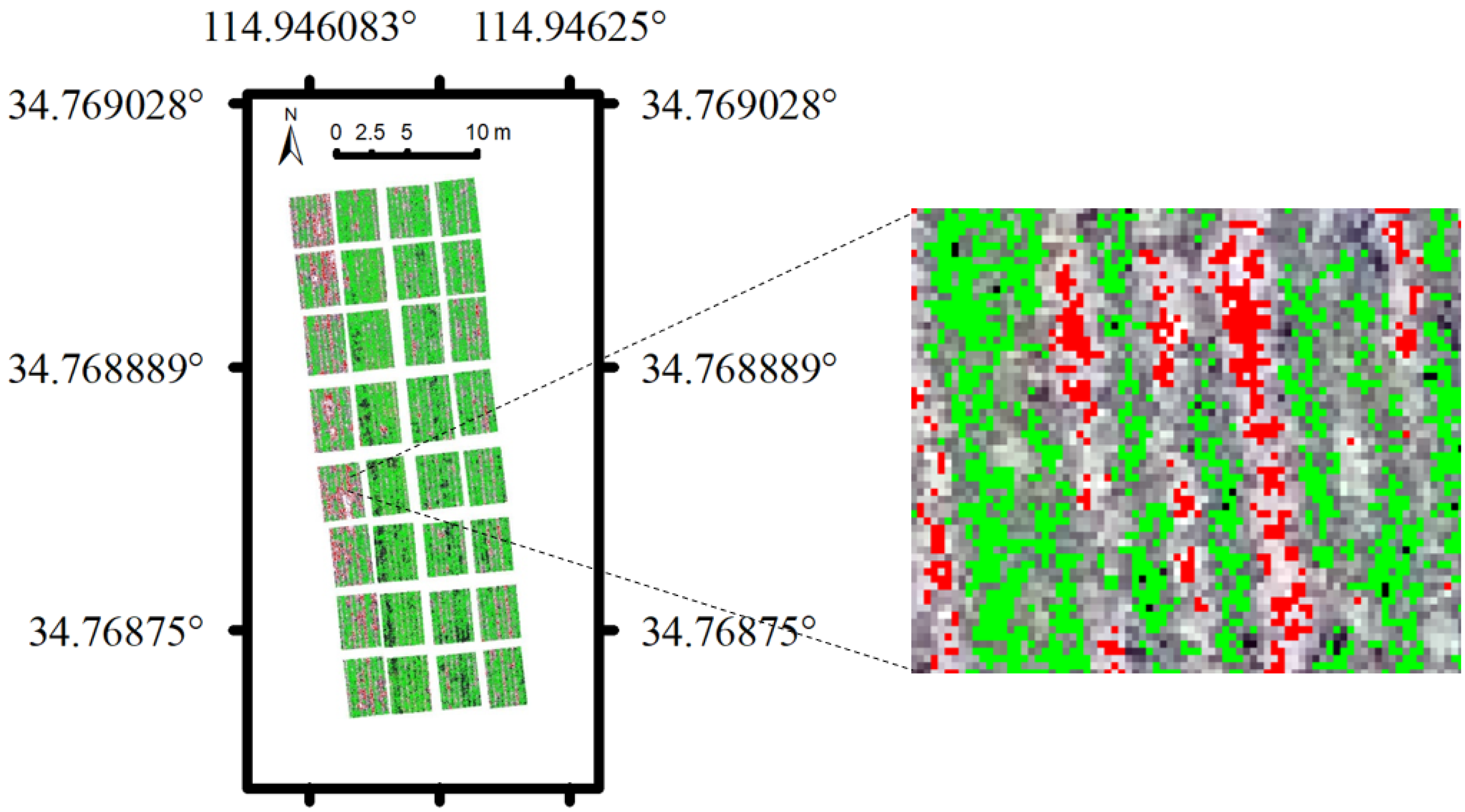
The first step of conducting linear mixed pixel decomposition is to extract endmembers from the UAV remote sensing imagery. Ridges between each plot were masked beforehand in order to eliminate the impacts of bare soil. According to the pure pixel index algorithm, each pixel is regarded as a 3-dimensional vector, corresponding to the reflectance values of the UAV remote sensing imagery’s blue, green, and red bands, and all pixels of the image construct a vector space [35]. By arbitrarily setting the basis of the vector space, all vectors can be expressed as the linear combination of the basis. Continuously and randomly redefining the basis of the vector space, 200 random vectors were generated. Finally, by projecting each pixel of the UAV remote sensing imagery onto these random vectors, endmembers of vegetation as well as soil were identified to be the pixels whose projection fell down to the edges of the random vectors over 20 times, which was set as the threshold value. As a result, 10,390 and 113,685 pixels were recognized as soil endmembers and vegetation endmembers, as shown in Figure 2 in red color and green color, and took up 3.2% and 34.9% of the wheat plots, respectively. All the other 61.9% of the pixels were considered as vegetationᯇ–soil mixed pixels of the UAV remote sensing imagery, which were decomposed using the linear unmixing method.
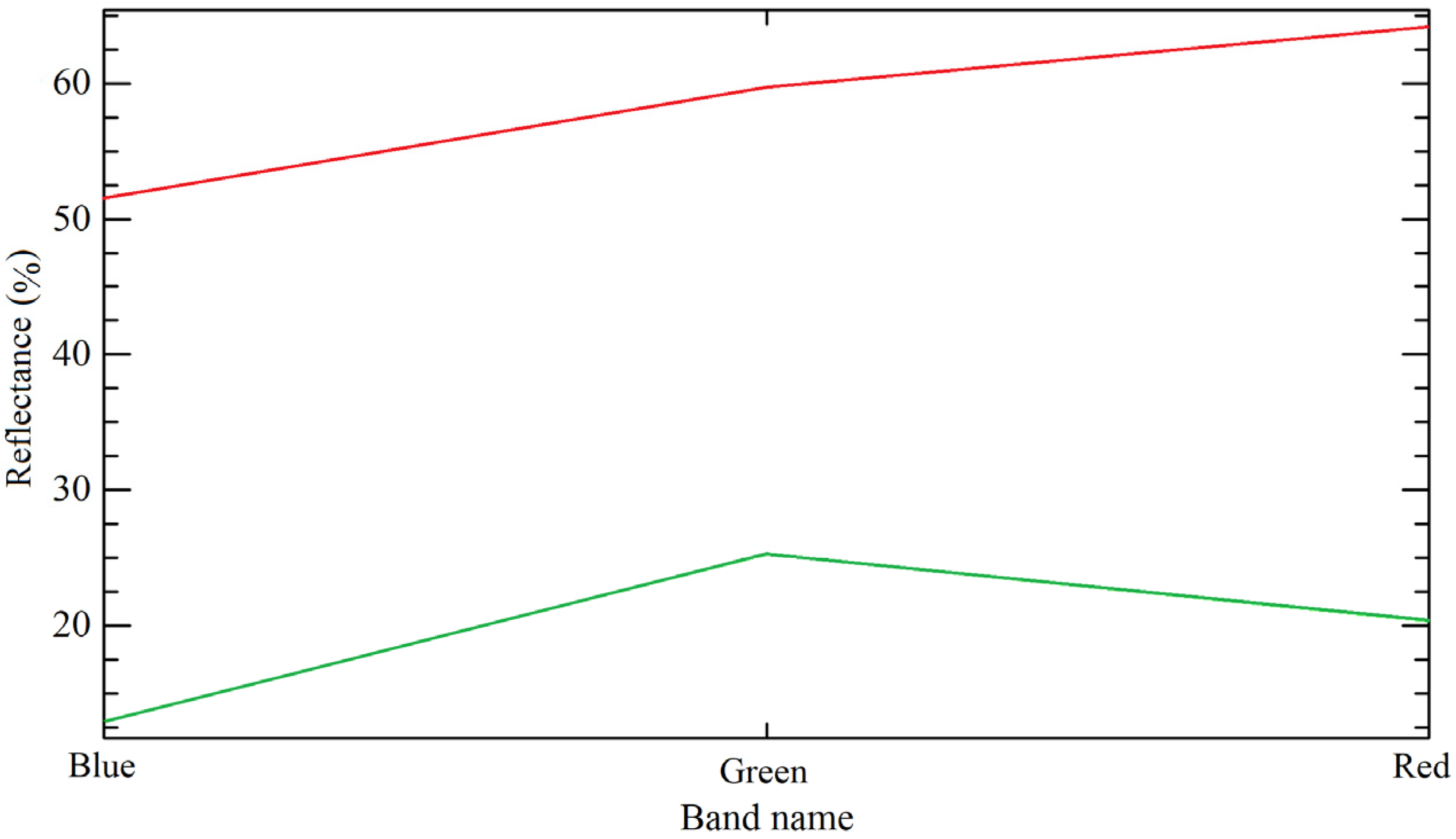
According to Figure 2, statistical data of reflectance of each endmember in the UAV remote sensing imagery were extracted, listed in Table 4. Spectral characteristics of vegetation endmembers as well as soil endmembers are shown in Figure 3.
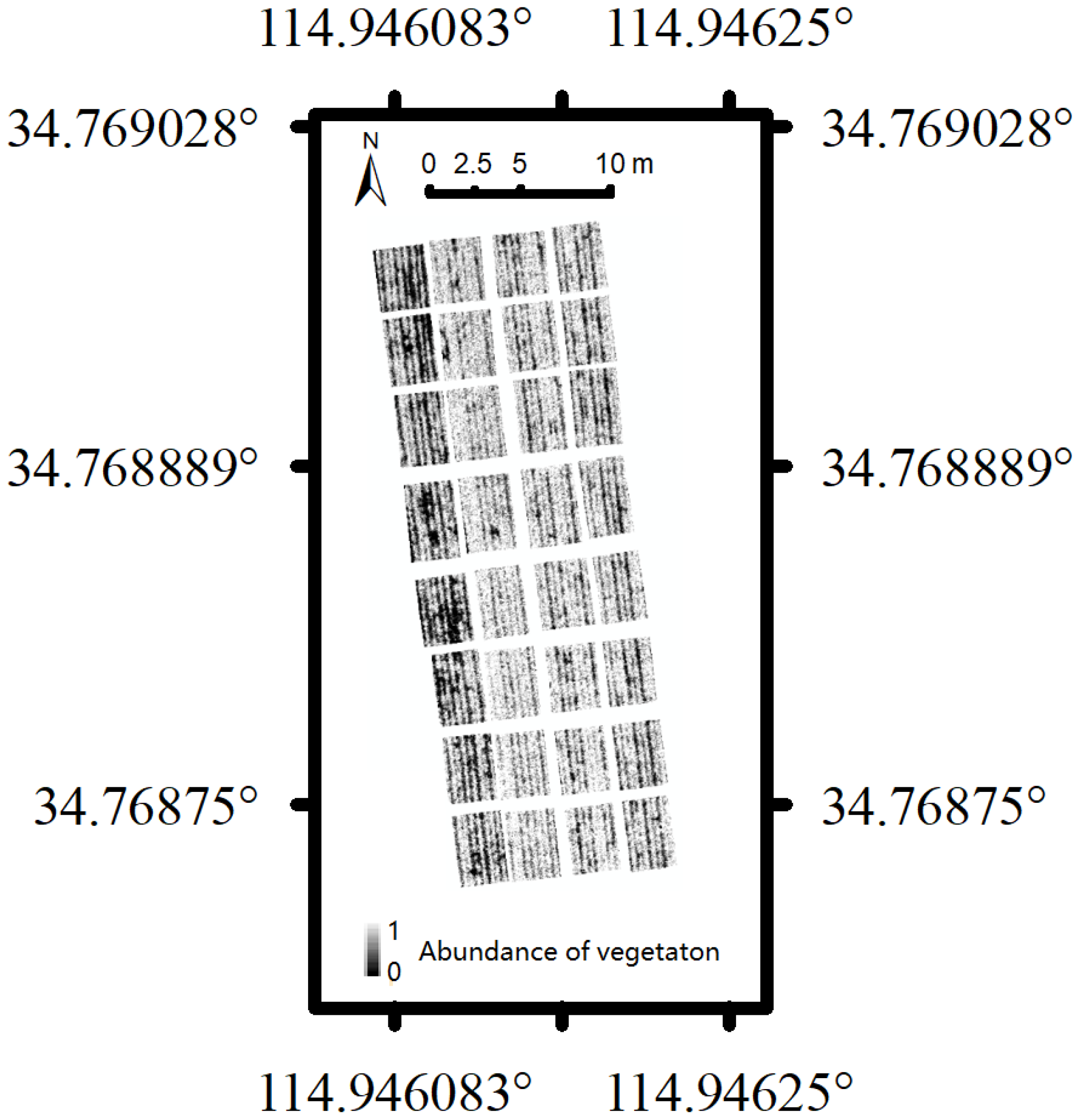
From Table 4 and Figure 3, it can be observed that the reflectance of vegetation endmembers is far less than that of the soil endmembers in each spectral band. In addition, the reflectance of vegetation endmembers increases from the blue band to the green band, but begins to decrease after reaching peak value in the green band. On the other hand, the reflectance of soil endmembers shows a steady growth trend with the increase of wavelength. Based on the statistical data of reflectance of the soil and vegetation endmembers, and according to the linear mixed pixel decomposition model expressed as Equation (2), mixed pixels of the UAV remote sensing image were finally decomposed with a unit sum constraint of 1. The abundance map of vegetation was obtained as Figure 4.
In Figure 4, soil endmembers were identified as dark pixels assigned with 0 and vegetation endmembers as white pixels with 1, while decimal fractions were given to the rest of the pixels as the abundance of vegetation, i.e., the proportion of the vegetation component in each mixed pixel. Therefore, the FVC of the corresponding “1-m-double-row” area of each plot was acquired based on the abundance map of vegetation according to Equation (3).
FVC   = N v   / N t
where Nv denotes the sum of the pixel number of vegetation endmembers and the vegetation abundances of the mixed pixels and Nt denotes the total number of pixels within the region of interest.

2.3. Image Segmentation

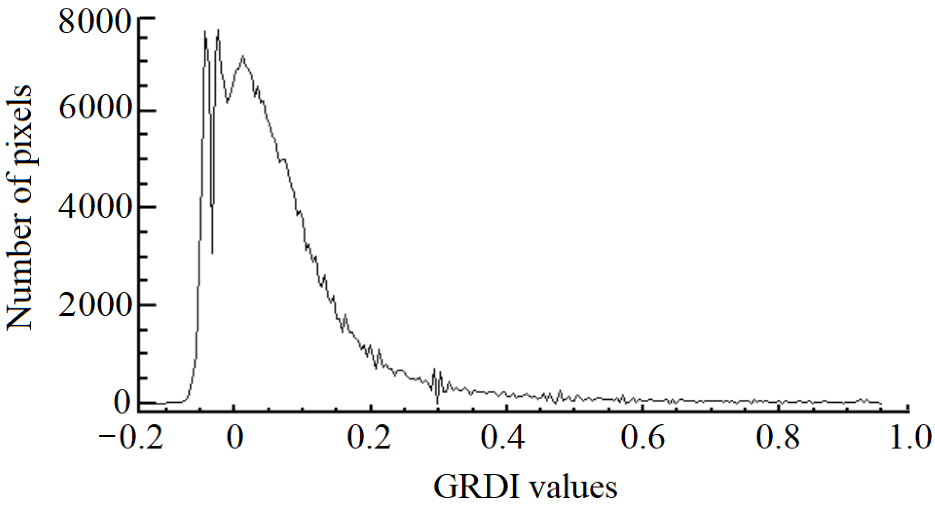
Image thresholding is the most straightforward and efficient method of segmenting grayscale images, and in this study a GRDI (green–red difference index) map was generated to enhance the distinction between vegetation and background (soil) of the UAV remote sensing image according to Equation (4) [36,37]. The bimodal characteristics of the GRDI map are shown in Figure 5, from which the thresholding value of image segmentation can be determined as −0.04.
GRDI   = Ref G Ref R /   Ref G + Ref R  
where RefG and RefR denote the reflectance of the green band and red band of the UAV remote sensing image, respectively.
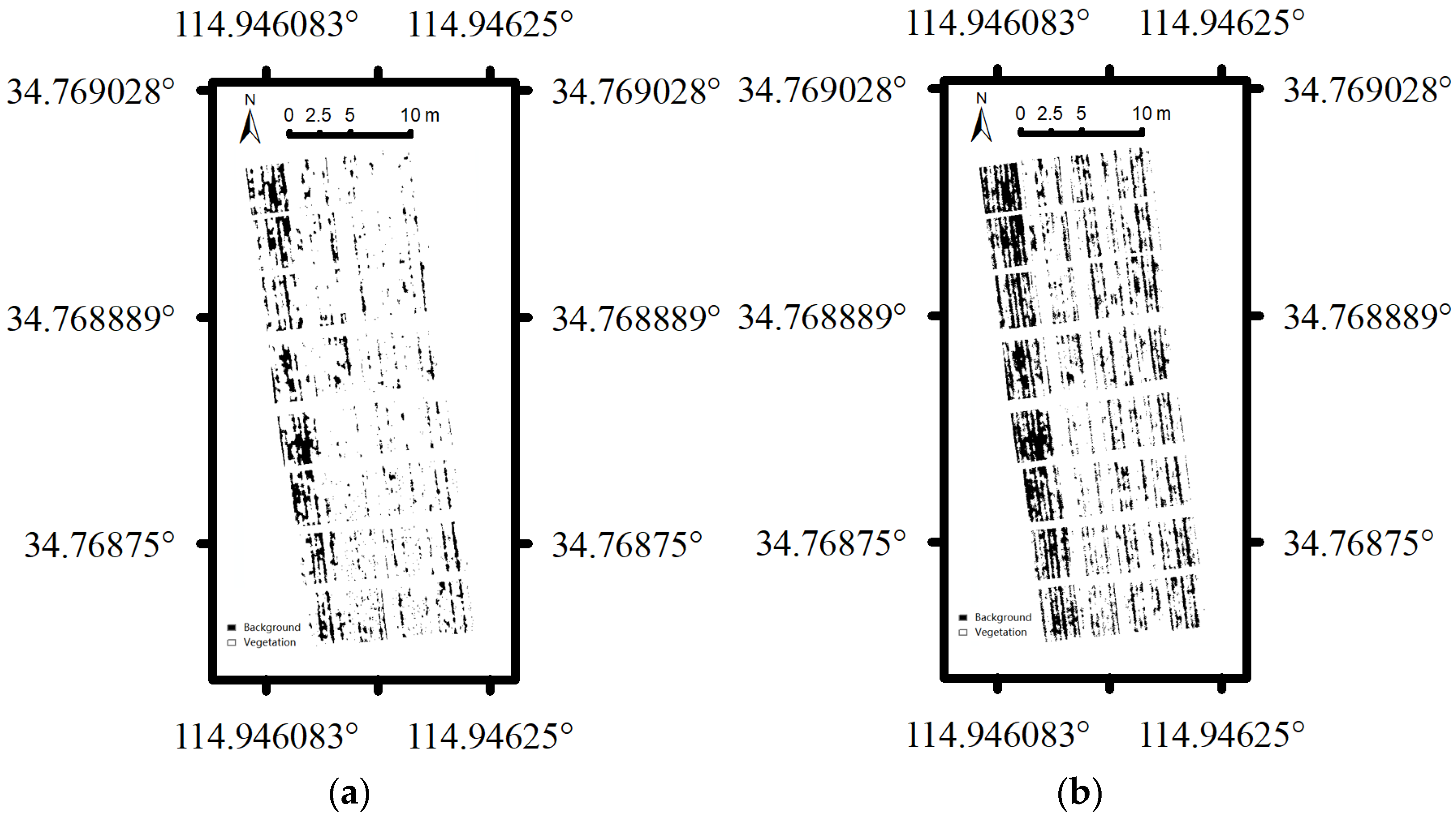
Consequently, 34,189 pixels in the UAV remote sensing image with GRDI value less than −0.04 were categorized as background, which accounted for 12.34% of the total pixels of the wheat field and are shown in Figure 6a in black color, while the other 87.66% of the pixels were considered as vegetation features and shown in white color.
A support vector machine (SVM) is a supervised machine learning model that is derived from statistical learning theory and used for building models of classification, regression, and outlier detection [38]. The SVM algorithm separates the classes of training data with a decision surface that maximizes the margin between each class from a local neighborhood point of view. Supervised image segmentation based on the SVM algorithm was conducted by manually annotating 800 pixels as vegetation and 800 pixels as background (soil) in the UAV remote sensing image. Thus, each pixel was categorized either to the class of vegetation or to the class of background according to the SVM classifier. The classification result is shown in Figure 6b. Background accounted for 62.21% of the total pixels of the wheat field, shown in black color, while the other 37.79% of the pixels are in white color, representing vegetation.

3. Results

3.1. FVC of Different Methods

The FVC values of the mixed pixel decomposition model, according to Equation (3), are listed in Table 5 as FVCMPD. It can be concluded that FVCMPD corresponding to different levels of wheat plant density varies from 0.389 to 0.871, which is evenly distributed within the theoretical range of 0 to 1.
In order to evaluate the accuracy of the FVCMPD, FVC based on the conventional image thresholding model and the machine learning SVM model was also acquired for comparative studies. By calculating the ratio of the number of pixels that were categorized as vegetation against the total number of pixels of the corresponding “1-m-double-row” area of each plot, FVCIT and FVCSVM are listed in Table 5 according to Figure 6a,b. From Table 5, the conclusion can be drawn that the FVCIT is distributed from 0.353 to 1, over two-thirds of which exceeds 0.9 and concentrates at the large end, indicating bad performance of distinguishing subtle differences among the areas of a high level of canopy coverage. The FVCSVM spread is from 0.289 to 0.998, which is uniformly distributed within the range of FVC.

3.2. Inverting Wheat Plant Density from FVC Values

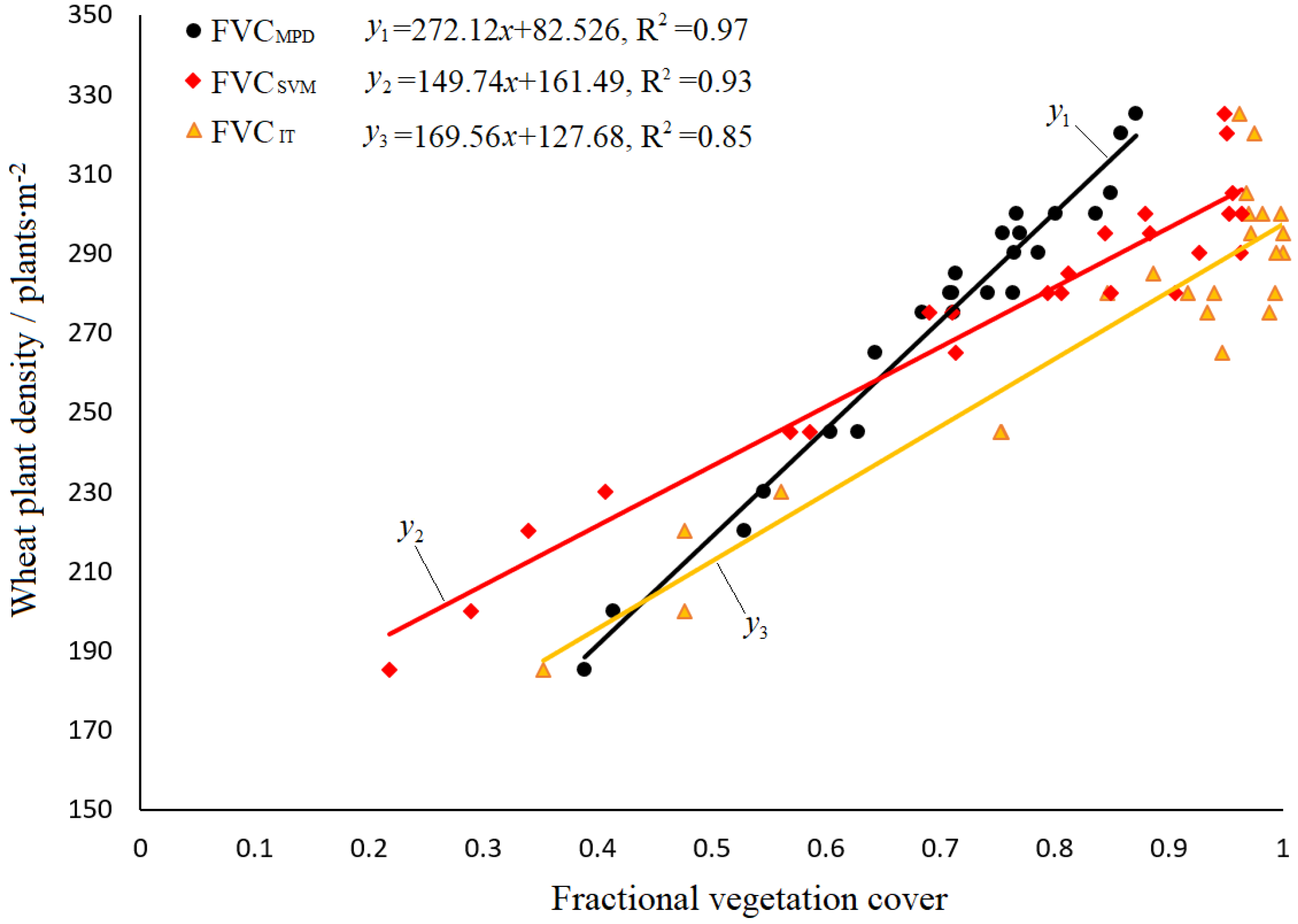
By using ground truth data of wheat plant density in Table 2 and FVC values based on the mixed pixel decomposition model, image thresholding model, and SVM model, linear regression models were established by randomly assigning 24 sets of training data, shown in Figure 7, while the other 8 sets (N1C, N2C, N3C, N4C, N1F, N2F, N3F, and N4F) were used as test data. The coefficient of determination (R2) of each linear regression model based on FVCMPD, FVCSVM, or FVCIT were determined to be 0.97, 0.93, and 0.85. Estimated wheat plant density for each test datum was calculated according to the linear regression models, listed in Table 6.
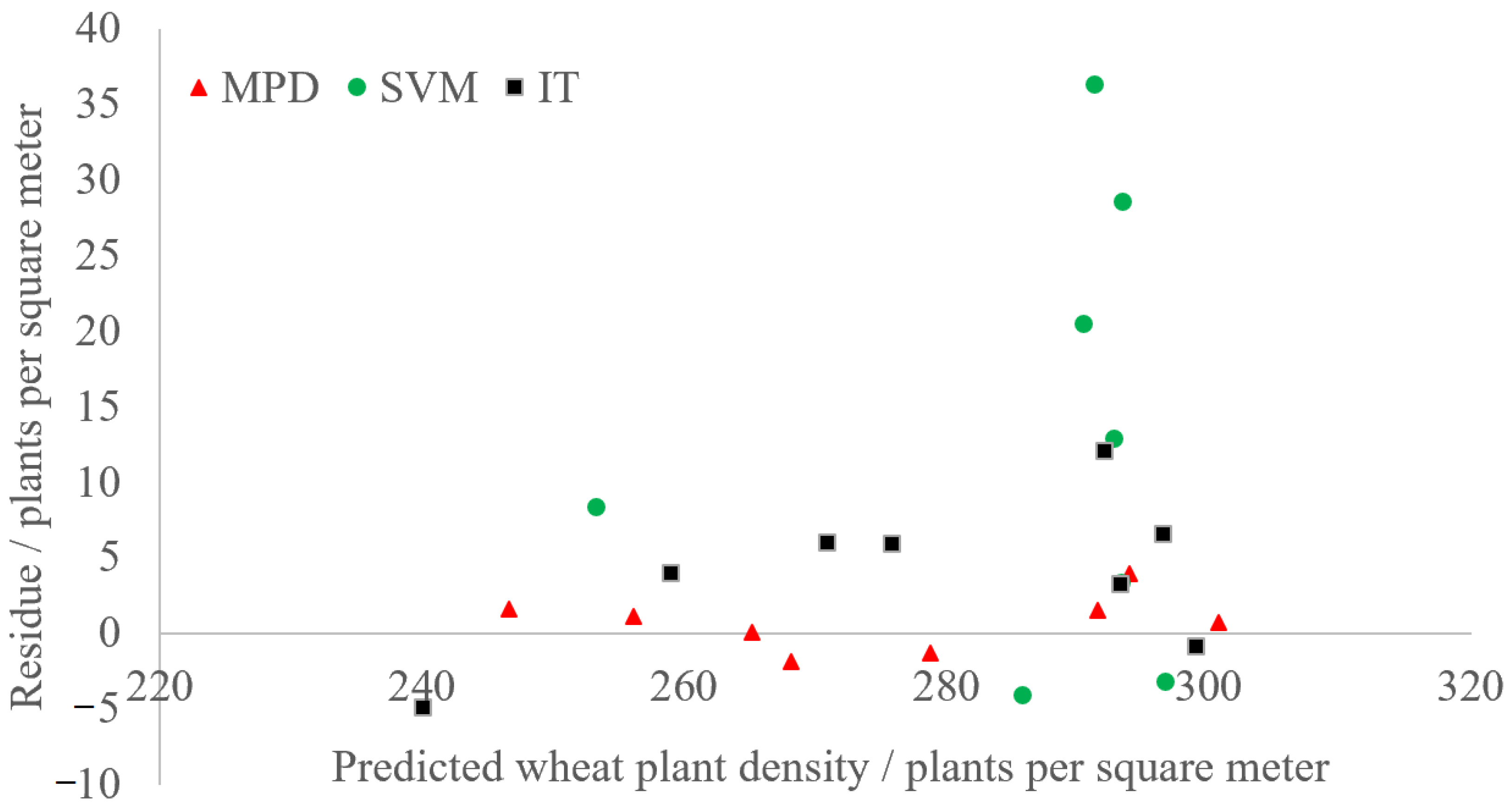
From Table 6, the residue plots of predicted wheat plant densities are drawn in Figure 8. It can be concluded that the predicted wheat plant density values based on FVCMPD are very close to each corresponding ground truth datum, while the ones based on FVCIT exhibited worst performance when compared with the ground truth data. Consequently, the RMSE (root mean square error) of the inversion models based on FVCMPD, FVCSVM, and FVCIT was calculated as 1.86, 6.22, and 18.78 plants/m2 according to Table 6. The RRMSE (relative RMSE) was calculated as 0.677%, 2.267%, and 6.844%, as the average wheat plant density of the ground truth data was calculated as 274.375 plants/m2. As a result, the conclusion was drawn that the FVCMPD based on the mixed pixel decomposition method has the best correlation with the ground truth data of wheat plant density. The accuracy of the wheat plant density inversion model with FVCMPD is less than the sampling error of the ground truth data (5 plants/m2), which indicates a significant advantage over FVCSVM and FVCIT.
Subsequently, a local sliding window of 40 pixels was applied to the abundance map of vegetation so that the experimental field was meshed into 1 m × 1 m grids. The FVCMPD of each grid was then calculated according to Equation (3). Finally, wheat plant density of each grid was estimated by using the linear regression model (y1 = 272.12x + 82.526). The map of estimated wheat plant density was generated as Figure 9, and statistical information of the minimum, maximum, and average of the estimated wheat plant density was calculated as 92.881, 384.406 and 271.657 plants/m2, which can be used as a prescription map for variable-rate nitrogenous topdressing in the wheat reviving period. The comparison of the enlarged map of estimated wheat plant density with the corresponding actual field image clearly indicates that the map can precisely describe the spatial variations in wheat plant density.

4. Discussion

4.1. Mixed Pixel Decomposition of UAV Remote Sensing Image

The increasing applications of UAV remote sensing technology provide a new way of obtaining field information both time- and cost-efficiently for precision agriculture. When UAV remote sensing images are applied to quantitative inversion research, special attention should be paid to mixed pixels, as the mixed pixel effect induces inconsistent findings in land surface phenology [21]. In our preliminary experiment, we established an inversion model of wheat plant density based on vegetation indices and overlooked mixed pixels of the UAV remote sensing images. The results indicate that the inversion accuracy was about 19 plants/m2, which provides new methods of quantifying wheat plant density in an open field environment but cannot meet the requirements for high precision of variable-rate nitrogenous topdressing [17]. The derivation of constituent endmembers and their abundances of mixed pixels has attracted our attention for improving the inversion accuracy of wheat plant density. In this study, as the constituent components of the UAV remote sensing image of the wheat field in the reviving period are simple, and the multi-scattering effect between vegetation and soil is negligible due to the short height of wheat stalks, the linear mixed pixel decomposition model was applied by using least square methods. Based on the spectral unmixing results, an abundance map of vegetation was obtained and FVC was accordingly calculated.

4.2. Inversion of Wheat Plant Density and Retrieval of FVC

Wheat plant density is a key agronomical indicator used to manage wheat crops. The information on wheat plant density is often acquired via manual counting and image processing. The coverage of manual counting is very small. Additionally, it is laborious and time consuming. On the other hand, estimating wheat plant density by means of image processing is attracting increasing attention. Liu et al. conducted near-ground remote sensing experiments on estimating wheat plant density for different sowing densities [9]. The camera was fixed on a ground platform at the distance of about 1.5 m above ground level, and the spatial resolution of the images was very high to 0.2 mm. By applying the Otsu automatic thresholding method, green pixels corresponding to the emerged plants were detected. As the result, wheat plant density was estimated with an average of 12% relative error. Jin et al. fixed a SONY ILCE α 5100 camera upon a hexacopter at the altitude of about 7 m above ground level and estimated wheat plant density at the emergence stage from the UAV (unmanned aerial vehicle) images by separating green pixels from the background [16]. The results show that the accuracy varied from 2.59 to 15.9 plants/m2 according to different cultivars. This research provided methods with good accuracy of estimating wheat plant density, but the ground-based platform or low altitude of the UAV restricted coverage and thus affected efficiency, which cannot be put into applications for large fields. In order to further improve the accuracy of inversion of wheat plant density, this study introduced FVC as the intermediate variable and discussed the mixed pixel decomposition method, SVM, and image thresholding method in the applications of estimating wheat plant density.
FVC is widely used as a quantitative indicator to describe the growth status of field crops [39] and is, in general, divided into the VI method and the image segmentation method in the remote sensing manner. Existing research has shown that correlation between the normalized difference vegetation index (NDVI) and FVC is significant [40], while the inversion accuracy of FVC based on the image segmentation method highly depends upon the applicability of image classification models. As remote sensing images of the consumer-level cameras of UAVs exclude the near-infrared band, NDVI is not available for accurate inversion of FVC. The accuracy of estimating FVC based on visible-band VI such as the visible-band difference vegetation index, green–red difference index, and green–red ratio index is too low to be used in quantifying wheat plant density in the reviving period, according to our preliminary experiment [17]. Therefore, this study put forward a new methodology of estimating FVC based on a mixed pixel decomposition model of the UAV remote sensing images, and an abundance map that indicated the proportion of vegetation in each mixed pixel was acquired to calculate the FVC values. The accuracy of FVC based on mixed pixel decomposition was evaluated by using ground truth data of wheat plant density, and the result was significantly improved to 1.86 plants/m2. However, due to significant diversities in phenotypic parameters among different wheat cultivars, the universality of the inversion models of wheat plant density remains to be further studied by taking parameters such as stalk height and length and width of wheat leaves into consideration.

5. Conclusions

In order to reduce the impact of mixed pixels on inverting wheat plant density in the reviving period, this study introduced a mixed pixel decomposition model to process the UAV remote sensing image, and an abundance map of the vegetation was acquired. Subsequently, FVC (fractional vegetation cover) was calculated and a linear regression model was obtained to estimate wheat plant density from FVC. The coefficient of determination (R2), RMSE (root mean square error) and RRMSE (Relative-RMSE) of the inversion model of wheat plant density were calculated as 0.97, 1.86 plants/m2, and 0.677%, which indicates that the FVC based on the mixed pixel decomposition method is highly correlated with wheat plant density in the reviving period.
For comparative study, this research also established linear regression models between the ground truth data of wheat plants and the FVC acquired by using a SVM (support vector machine) method as well as the image thresholding method. The R2, RMSE, and RRMSE of each inversion model were calculated as 0.93, 6.22 plants/m2, 2.267% and 0.85, 18.78 plants/m2, and 6.844%. Therefore, we can conclude that the mixed pixel decomposition model of the UAV remote sensing image significantly improves the inversion accuracy of wheat plant density from FVC values, and the inversion accuracy is less than the sampling error of the ground truth data (5 plants/m2), which provides method support and basic data for variable-rate nitrogenous fertilization in the wheat reviving period.

Author Contributions

Conceptualization, M.D., M.L., N.N. and J.J.; methodology, M.D.; validation, M.D.; formal analysis, M.D.; investigation, M.D.; resources, M.D.; data curation, M.D.; writing—original draft preparation, M.D.; writing—review and editing, M.D. and M.(G.)Y.; project administration, M.D. and J.J.; funding acquisition, M.D. and M.L. All authors have read and agreed to the published version of the manuscript.

Funding

This research was funded by National Key Research & Development Program of China, grant number 2019YFE0125500.

Institutional Review Board Statement

Not applicable.

Informed Consent Statement

Not applicable.

Data Availability Statement

Not applicable.

Conflicts of Interest

The authors declare no conflict of interest. The funders had no role in the design of the study; in the collection, analyses, or interpretation of data; in the writing of the manuscript; or in the decision to publish the results.

References

  1. Shewry, R.; Hey, J. The Contribution of Wheat to Human Diet and Health. Food Energy Secur. 2015, 4, 178–202. [Google Scholar] [CrossRef] [PubMed]
  2. Maik, R.; Eduardo, C.; Ricardo, L.; Zielinski, A.; Granato, D.; Demiate, I. Wheat Technological Quality as Affected by Nitrogen Fertilization under a no-till System. Acta. Sci. Technol. 2015, 37, 175–181. [Google Scholar]
  3. Sasaki, R.; Toriyama, K. Nitrogen Content of Leaves Affects the Nodal Position of the Last Visible Primary Tiller on Main Stems of Rice Plants Grown at Various Plant Densities. Plant Prod. Sci. 2006, 9, 242–248. [Google Scholar] [CrossRef]
  4. Wang, R.; Wang, H.; Jiang, G.; Yin, H.; Che, Z. Effects of Nitrogen Application Strategy on Nitrogen Enzyme Activities and Protein Content in Spring Wheat Grain. Agriculture 2022, 12, 1891. [Google Scholar] [CrossRef]
  5. Walsh, O.; Klatt, A.; Solie, J.; Godsey, B.; Raun, R. Use of Soil Moisture Data for Refined GreenSeeker Sensor Based Nitrogen Recommendations in Winter Wheat (Triticum Aestivum L.). Precis. Agric. 2013, 14, 343–356. [Google Scholar] [CrossRef] [Green Version]
  6. Schwerz, F.; Caron, B.; Schmidt, D.; de Oliveira, M.; Elli, F.; Eloy, E.; Rockenbach, P. Growth Retardant and Nitrogen Levels in Wheat Agronomic Characteristics. Cientifica 2015, 43, 93–100. [Google Scholar] [CrossRef] [Green Version]
  7. Sellamuthu, M.; Santhi, R.; Maragatham, S.; Dey, P. Validation of Soil Test and Yield Target Based Fertilizer Prescription Model for Wheat on Inceptisol. Res. Crops 2015, 16, 53–58. [Google Scholar] [CrossRef]
  8. Liu, T.; Yang, T.; Li, C.; Li, R.; Wu, W.; Zhong, X.; Guo, W. A Method to Calculate the Number of Wheat Seedlings in the 1st to the 3rd Leaf Growth Stages. Plant Methods 2018, 14, 101. [Google Scholar] [CrossRef]
  9. Liu, S.; Baret, F.; Andrieu, B.; Burger, P.; Hemmerlé, M. Estimation of Wheat Plant Density at Early Stages Using High Resolution Imagery. Front. Plant Sci. 2017, 8, 739. [Google Scholar]
  10. Shi, G.; Du, X.; Du, M.; Li, Q.; Tian, X.; Ren, Y.; Wang, H. Cotton Yield Estimation Using the Remote sensing Cotton Boll Index from UAV Images. Drones 2022, 6, 254. [Google Scholar] [CrossRef]
  11. Clement, A. Advances in Remote Sensing of Agriculture: Context Description, Existing Operational Monitoring Systems and Major Information Needs. Remote Sens. 2013, 5, 949–981. [Google Scholar]
  12. Kedia, A.C.; Kapos, B.; Liao, S.; Draper, J.; Eddinger, J.; Updike, C.; Frazier, E. An Integrated Spectral–Structural Workflow for Invasive Vegetation Mapping in an Arid Region Using Drones. Drones 2021, 5, 19. [Google Scholar] [CrossRef]
  13. Wu, Q.; Wang, C.; Fang, J.; Jianwei, J. Field Monitoring of Wheat Seedling Stage with Hyperspectral Imaging. Int. J. Agric. Biol. Eng. 2016, 9, 143–148. [Google Scholar]
  14. Du, M.; Noguchi, N. Monitoring of Wheat Growth Status and Mapping of Wheat Yield’s within-Field Spatial Variations Using Color Images Acquired from UAV-Camera System. Remote Sens. 2017, 9, 289. [Google Scholar] [CrossRef]
  15. Montgomery, K.; Henry, J.B.; Vann, M.C.; Whipker, B.E.; Huseth, A.S.; Mitasova, H. Measures of Canopy Structure from Low-Cost UAS for Monitoring Crop Nutrient Status. Drones 2020, 4, 36. [Google Scholar] [CrossRef]
  16. Jin, X.; Liu, S.; Frederic, B.; Hemerlé, M.; Comar, A. Estimates of Plant Density of Wheat Crops at Emergence from Very Low Altitude UAV Imagery. Remote Sens. Environ. 2017, 198, 105–114. [Google Scholar] [CrossRef] [Green Version]
  17. Du, M.; Ali, R.; Liu, Y. Inversion of Wheat Tiller Density Based on Visible-Band Images of Drone. Spectrosc. Spectr. Anal. 2021, 41, 3828–3836. [Google Scholar]
  18. Carlson, N.; Ripley, A. On the Relation between NDVI, Fractional Vegetation Cover, and Leaf Area Index. Remote Sens. Environ. 1997, 62, 241–252. [Google Scholar] [CrossRef]
  19. Yue, J.; Guo, W.; Yang, G.; Zhou, C.; Feng, H.; Qiao, H. Method for Accurate Multi-Growth-Stage Estimation of Fractional Vegetation Cover Using Unmanned Aerial Vehicle Remote Sensing. Plant Methods 2021, 17, 51. [Google Scholar] [CrossRef]
  20. Evans, A.D.; Gardner, K.H.; Greenwood, S.; Still, B. UAV and Structure-From-Motion Photogrammetry Enhance River Restoration Monitoring: A Dam Removal Study. Drones 2022, 6, 100. [Google Scholar] [CrossRef]
  21. Chen, X.; Wang, D.; Chen, J.; Wang, C.; Shen, M. The Mixed Pixel Effect in Land Surface Phenology: A Simulation Study. Remote Sens. Environ. 2018, 211, 338–344. [Google Scholar] [CrossRef]
  22. Jones, G.; Sirault, R. Scaling of Thermal Images at Different Spatial Resolution: The Mixed Pixel Problem. Agronomy 2014, 4, 380–396. [Google Scholar] [CrossRef] [Green Version]
  23. Nghiyalwa, S.; Urban, M.; Baade, J.; Smit, I.P.; Ramoelo, A.; Mogonong, B.; Schmullius, C. Spatio-Temporal Mixed Pixel Analysis of Savanna Ecosystems: A Review. Remote Sens. 2021, 13, 3870. [Google Scholar] [CrossRef]
  24. Sivanandam, P.; Lucieer, A. Tree Detection and Species Classification in a Mixed Species Forest Using Unoccupied Aircraft System (UAS) RGB and Multispectral Imagery. Remote Sens. 2022, 14, 4963. [Google Scholar] [CrossRef]
  25. Mani, P.; Rajendiran, S.; Aruldoss, K.; Elanchezhian, G. Mixed Pixel Removal in North Tamil Nadu Region for Accurate Area Measurement. Comput. Intell. 2021, 37, 975–994. [Google Scholar] [CrossRef]
  26. Wu, S.; Ren, J.; Chen, Z.; Jin, W.; Liu, X.; Li, H.; Guo, W. Influence of Reconstruction Scale, Spatial Resolution and Pixel Spatial Relationships on the Sub-pixel Mapping Accuracy of a Double-Calculated Spatial Attraction Model. Remote Sens. Environ. 2018, 210, 345–361. [Google Scholar] [CrossRef]
  27. Rauf, U.; Qureshi, S.; Jabbar, H.; Zeb, A.; Mirza, A.; Alanazi, E.; Rashid, N. A New Method for Pixel Classification for Rice Variety Identification Using Spectral and Time Series Data from Sentinel-2 Satellite Imagery. Comput. Electron. Agric. 2022, 193, 106731. [Google Scholar] [CrossRef]
  28. Chang, I.; Zhao, L.; Althouse, L.; Pan, J.J. Least Squares Subspace Projection Approach to Mixed Pixel Classification for Hyperspectral Images. IEEE Trans. Geosci. Remote Sens. 1998, 36, 898–912. [Google Scholar] [CrossRef] [Green Version]
  29. Plaza, A.; Martinez, P.; Perez, R.; Plaza, J. A New Approach to Mixed Pixel Classification of Hyperspectral Imagery Based on Extended Morphological Profiles. Pattern Recognit. 2004, 37, 1097–1116. [Google Scholar] [CrossRef]
  30. Miao, L.; Qi, H.; Harold, S. A Maximum Entropy Approach to Unsupervised Mixed-Pixel Decomposition. IEEE Trans. Image Process. 2007, 16, 1008–1021. [Google Scholar] [CrossRef]
  31. Khodadadzadeh, J.; Plaza, A.; Ghassemian, H.; Ghassemian, H.; Bioucas-Dias, J.M.; Li, X. Spectral–Spatial Classification of Hyperspectral Data Using Local and Global Probabilities for Mixed Pixel Characterization. IEEE Trans. Geosci. Remote Sens. 2014, 52, 6298–6314. [Google Scholar] [CrossRef]
  32. Kim, S.; Miller, C.; Bethel, J. Automated Georeferencing of Historic Aerial Photography. J. Terr. Obs. 2010, 2, 6. [Google Scholar]
  33. Doelling, R.; Morstad, D.; Scarino, R.; Bhatt, R.; Gopalan, A. The Characterization of Deep Convective Clouds as an Invariant Calibration Target and as a Visible Calibration Technique. IEEE Trans. Geosci. Remote Sens. 2012, 51, 1147–1159. [Google Scholar] [CrossRef]
  34. He, Q.; Zhang, Y.; Liang, L. Application of Linear Spectral Mixed Pixel Decomposition Technology in Extracting the Spatial Distribution of Illicit Opium Poppy Cultivation. Optik 2022, 271, 170104. [Google Scholar] [CrossRef]
  35. Hsueh, M.; Chang, I. Field Programmable Gate Arrays (FPGA) for Pixel Purity Index Using Blocks of Skewers for Endmember Extraction in Hyperspectral Imagery. Int. J. High Perform. Comput. Appl. 2008, 22, 408–423. [Google Scholar] [CrossRef]
  36. Kaushalya, G.; Bhujel, A.; Kim, E.; Kim, H.T. Measurement of Overlapping Leaf Area of Ice Plants Using Digital Image Processing Technique. Agriculture 2022, 12, 1321. [Google Scholar] [CrossRef]
  37. Zamani-Noor, N.; Feistkorn, D. Monitoring Growth Status of Winter Oilseed Rape by NDVI and NDYI Derived from UAV-Based Red–Green–Blue Imagery. Agronomy 2022, 12, 2212. [Google Scholar] [CrossRef]
  38. Ziyaee, P.; Ahmadi, V.F.; Bazyar, P.; Cavallo, E. Comparison of Different Image Processing Methods for Segregation of Peanut (Arachis hypogaea L.) Seeds Infected by Aflatoxin-Producing Fungi. Agronomy 2021, 11, 873. [Google Scholar] [CrossRef]
  39. Tang, L.; He, M.; Li, X. Verification of Fractional Vegetation Coverage and NDVI of Desert Vegetation via UAVRS Technology. Remote Sens. 2020, 12, 1742. [Google Scholar] [CrossRef]
  40. Gutman, G.; Ignatov, A. The Derivation of the Green Vegetation Fraction from NOAA/AVHRR Data for Use in Numerical Weather Prediction Models. Int. J. Remote Sens. 1998, 19, 1533–1543. [Google Scholar] [CrossRef]
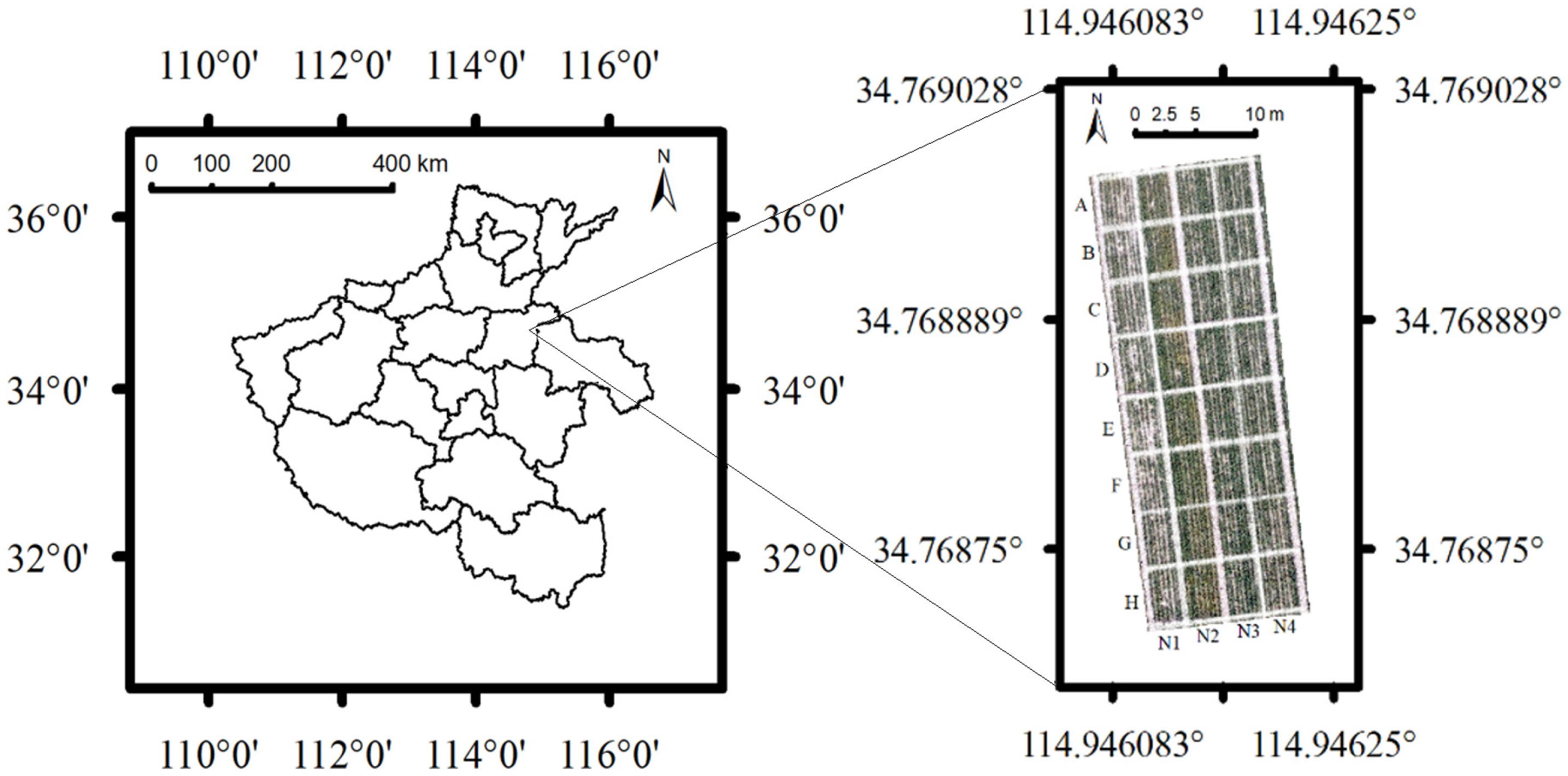
Figure 1. Plots of experimental wheat field.
Drones 07 00043 g001
Figure 2. Identification of vegetation endmembers (pixels in green color) and soil endmembers (pixels in red color).
Drones 07 00043 g002
Figure 3. Spectral characteristics of vegetation endmembers (in green color) and soil endmembers (in red color).
Drones 07 00043 g003
Figure 4. Abundance map of vegetation.
Drones 07 00043 g004
Figure 5. Bimodal characteristics of the green–red difference index map.
Drones 07 00043 g005
Figure 6. Image segmentation results:(a) image thresholding method; (b) support vector machine method.
Drones 07 00043 g006
Figure 7. Wheat plant density inversion models based on FVC values calculated by using different methods. Note: FVCMPD, FVCSVM, and FVCIT indicate the FVC (fractional vegetation cover) calculated by using mixed pixel decomposition, image thresholding, and the SVM method. y1, y2, and y3 indicate the predicted wheat plant density from FVCMPD, FVCSVM, and FVCIT, respectively.
Drones 07 00043 g007
Figure 8. Residue plots of predicted wheat plant densities by using different inversion models. Note: MPD, SVM, and IT indicate the methods of mixed pixel decomposition, support vector machine, and image thresholding.
Drones 07 00043 g008
Figure 9. Map of estimated wheat plant density.
Drones 07 00043 g009
Table 1. Equipment of wheat field remote sensing experiment.
EquipmentItemsValues
UAV Overall size (mm)245 × 289 × 56
Net weight (g) 249
Altitude (m/s)80
Ground sampling distance (cm)2.5
Imaging SensorAngle of view (°)83
Type of imagerCMOS
Effective pixels2250 × 4000
Equivalent focal length (mm)24
Exposure time (s)1/1000
ISO sensitivity100
Spectral bandRGB
Table 2. Ground truth data of wheat plant density.
Nitrogen TreatmentWheat Plant Density of Each Plot (Plants/m2)
ABCDEFGH
N1230200255245185245220245
N2285280280290295290280300
N3265295300305300290320325
N4280300265275290270275280
Table 3. Wheat plant number within the “1-m-double-row” areas.
Nitrogen TreatmentWheat Plants Number of Each Plot
ABCDEFGH
N14640514937494449
N25756565859585660
N35359606160586465
N45660535558545556
Table 4. Statistical data of reflectance of vegetation endmembers and soil endmembers.
Endmember CategorySpectral BandAverage of ReflectanceStandard Deviation of Reflectance
Blue0.1180.055
VegetationGreen0.2410.056
Red0.1910.065
Blue0.520.032
SoilGreen0.6020.027
Red0.6450.029
Table 5. FVC of different methods of the “1-m-double-row” area of each plot.
PlotFVCPlotFVC
FVCMPDFVCITFVCSVMFVCMPDFVCITFVCSVM
N1A0.5460.5610.407N3A0.6430.9470.714
N1B0.4140.4760.289N3B0.7550.9720.844
N1C0.6380.9650.651N3C0.8020.9970.919
N1D0.6040.7540.569N3D0.8490.9680.956
N1E0.3890.3530.218N3E0.8360.9820.953
N1F0.6030.7410.525N3F0.7770.9770.902
N1G0.5290.4760.339N3G0.8580.9750.951
N1H0.6280.7530.586N3H0.8710.9620.949
N2A0.7140.8860.812N4A0.7420.9930.906
N2B0.7090.9170.794N4B0.8010.9980.964
N2C0.7210.9740.872N4C0.6710.9780.731
N2D0.76510.963N4D0.6840.9820.69
N2E0.7710.883N4E0.7860.9940.927
N2F0.7680.9330.88N4F0.6820.960.764
N2G0.7110.8460.806N4G0.7120.9340.711
N2H0.7670.970.879N4H0.7640.940.849
Note: FVCMPD,FVCIT, and FVCSVM indicate the FVC based on mixed pixel decomposition, image thresholding, and support vector machine method, respectively.
Table 6. Estimated wheat plant density from FVC values.
PlotEstimated Wheat Plant Density from FVC Values (Plants/m2)Ground Truth of Test Data
(Plants/m2)
FVCMPDFVCITFVCSVM
N1C256.138291.305258.970255
N2C278.724292.831292.063280
N3C300.766296.731299.101300
N4C265.118293.509270.949265
N1F246.614253.323240.103245
N2F291.514285.879293.261290
N3F293.963293.340296.555290
N4F268.111290.457275.891270
Disclaimer/Publisher’s Note: The statements, opinions and data contained in all publications are solely those of the individual author(s) and contributor(s) and not of MDPI and/or the editor(s). MDPI and/or the editor(s) disclaim responsibility for any injury to people or property resulting from any ideas, methods, instructions or products referred to in the content.