Article

A Real-Time and Multi-Sensor-Based Landing Area Recognition System for UAVs

1
Faculty of Robot Science and Engineering, Northeastern University, Shenyang 110819, China
2
Science and Technology on Near-Surface Detection Laboratory, Wuxi 214000, China
*
Author to whom correspondence should be addressed.
These authors contributed equally to this work.
Drones 2022, 6(5), 118; https://doi.org/10.3390/drones6050118
Submission received: 4 April 2022 / Revised: 28 April 2022 / Accepted: 2 May 2022 / Published: 7 May 2022
(This article belongs to the Section Drone Design and Development)

Abstract

:
This paper presents a real-time and multi-sensor-based landing area recognition system for UAVs, which aims to enable UAVs to land safely on open and flat terrain and is suitable for comprehensive unmanned autonomous operation. The landing area recognition system for UAVs is built on the combination of a camera and a 3D LiDAR. The problem is how to fuse the image and point cloud information and realize the landing area recognition to guide the UAV landing autonomously and safely. To solve this problem, firstly, we use a deep learning method to realize the landing area recognition and tracking from images. After that, we project 3D LiDAR point cloud data into camera coordinates to obtain the semantic label of each point. Finally, we use the 3D LiDAR point cloud data with the semantic label to build the 3D environment map and calculate the most suitable area for UAV landing. Experiments show that the proposed method can achieve accurate and robust recognition of landing area for UAVs.

1. Introduction

Generally speaking, existing UAVs have high requirements for the terrain of the landing area. If the landing area is uneven, it may cause the UAV to overturn, which will not only seriously damage the UAV and destroy the ground facilities but can also cause harm to pedestrians on the ground. For existing autonomous UAV landing systems, it is usually necessary to set a fixed safe landing area and ensure that the landing area is relatively open and flat. Image or LiDAR sensors can be used to guide the UAV to achieve safe and autonomous landing. However, in most cases, the UAV does not have a priori information about the terrain of the landing area, such as disaster relief, geographic information survey and express delivery. In this kind of task, it is necessary for the people to monitor the landing situation or use manual remote control to land UAVs, which seriously affects the efficiency of the overall unmanned autonomous operation. In addition, in some emergencies, such as fuel shortage, signal loss and weather change, the UAV needs to land autonomously in unknown terrain areas. However, existing UAV systems do not have corresponding emergency response strategies.
Therefore, the autonomous recognition of a landing area is very important for UAVs. It can realize the comprehensive unmanned autonomous operation of UAVs, benefit the development of related applications, and avoid unnecessary risks and losses. The existing similar research is mainly divided into two streams: The first one pays attention to the mechanical structure design and control strategy of the UAV landing gear and does not actively acquire the terrain information of the landing area. For example, Sarkisov [1] designed a landing gear that can automatically adapt to the terrain of the landing point and automatically adjust the length of the landing gear and the contact angle with the ground according to the feedback of sensors during landing. For the second one, the UAV is equipped with sensors to obtain the terrain information of the landing area in real-time and is guided to land autonomously and safely based on the acquired terrain information. There have been various recent research efforts for the successful landing of UAVs, and most of them have used vision sensors [2,3,4,5,6,7].
The goal of this paper is to propose an autonomous and safe landing solution. The existing methods for autonomous landing are mainly based on a single sensor to realize the recognition and tracking of the landing area and guide the UAV to achieve safe and autonomous landing. According to the different sensors used, these studies can be divided into three categories: landing area recognition based on a monocular camera [8,9,10,11,12,13,14,15,16,17,18], landing area recognition based on a stereo camera [19,20,21,22,23,24], and landing area recognition based on 3D LiDAR [25,26,27,28,29,30]. Although these methods have good performance in some specific scenes, it is difficult to identify the landing area accurately and stably in some more complex scenes or with poor illumination.
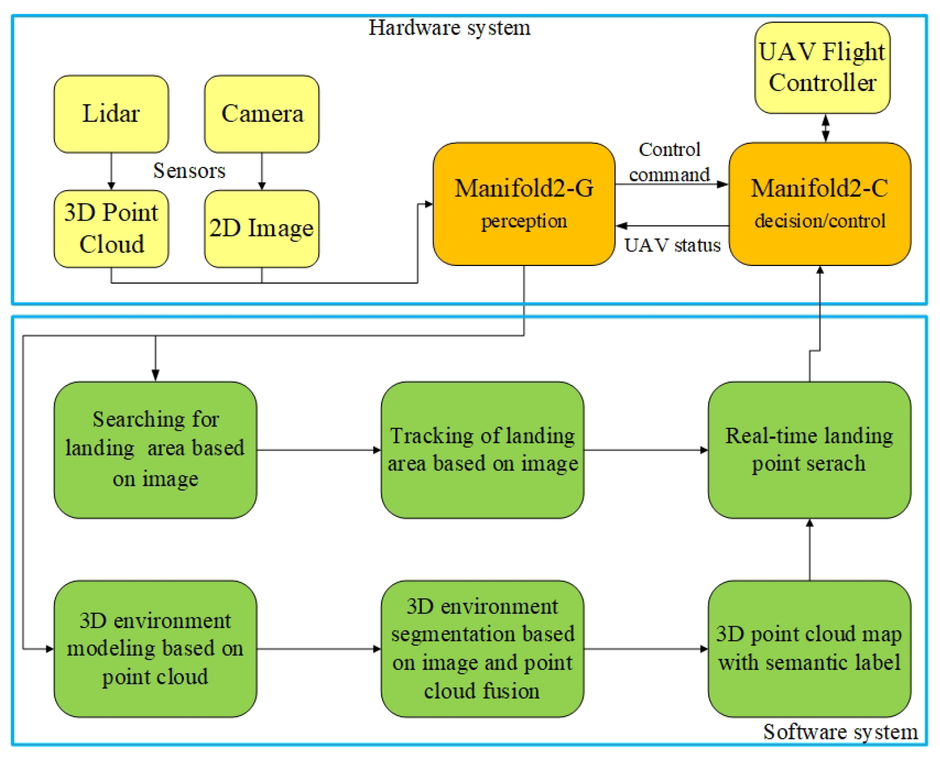
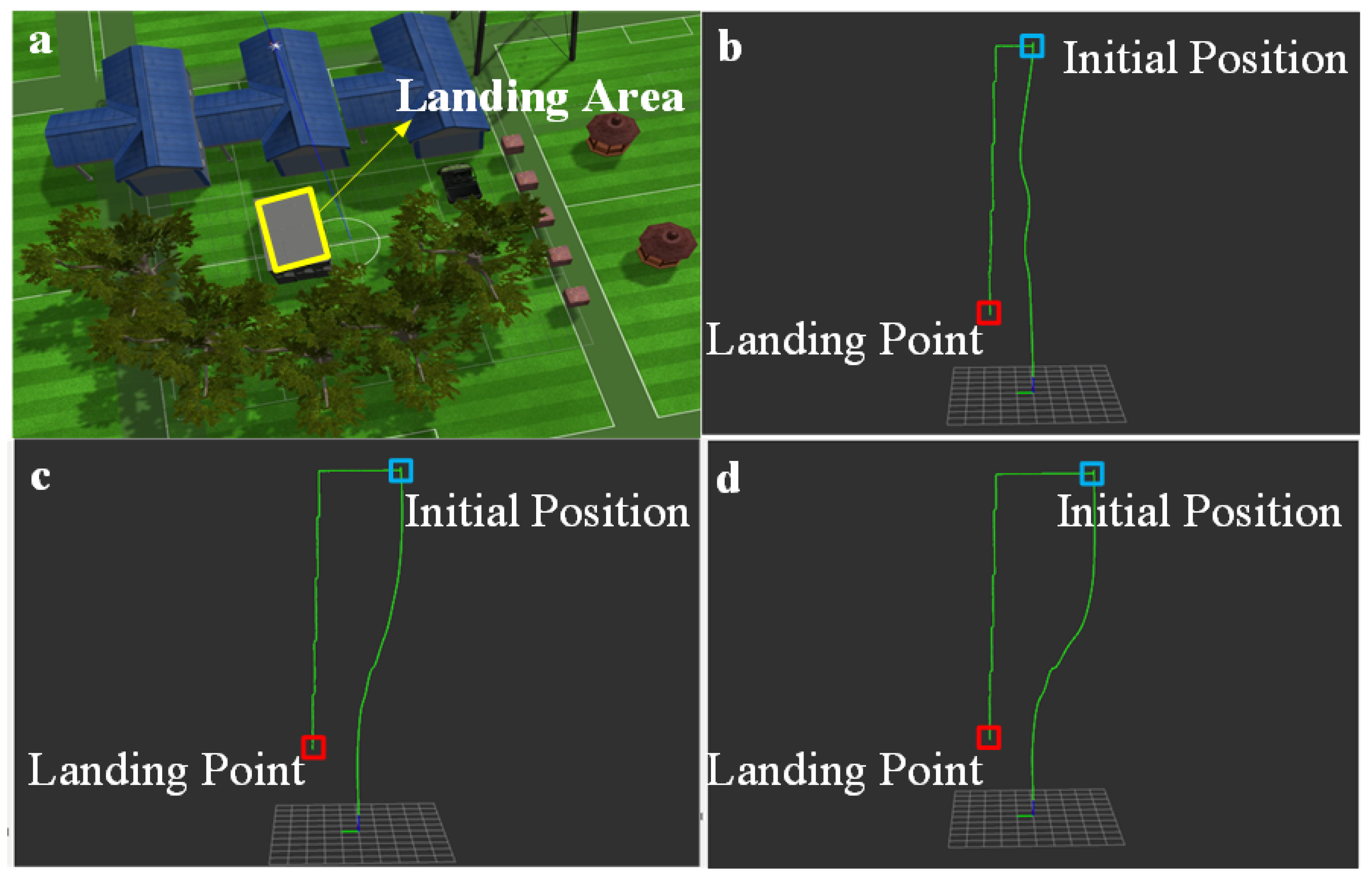
Therefore, in order to solve this problem, this paper proposes a UAV landing area recognition system based on multi-sensor fusion. This system firstly uses the method based on image semantic segmentation to identify the landing area below the UAV, uses image target tracking to guide the UAV to fly towards the landing area, and finally uses the fusion data of the image and point cloud to realize safe and autonomous landing. From simulation and real experimental tests, it is shown that the system can realize a robust recognition of the landing area and guide the UAV to land safely.

2. Related Works

2.1. Methods Based on Monocular Camera

Some researchers pay attention to the study on the recognition method of landing area. Some early methods are based on the known landing areas to realize the recognition of UAV’s landing areas. Barber et al. [8] proposed a method for using vision-based feedback to land a miniature air vehicle accurately on a visually identifiable target of approximately known location. Millet et al. [9] presented a method to perform precision landings of a tailsitter unmanned air vehicle (UAV) using an onboard camera, the UAV’s orientation, and its altitude above ground level (AGL). Recently, some methods select the area suitable for UAV landing by extracting the features of the area under the UAV. Desaraju et al. [10] employed an active perception strategy utilizing Gaussian processes to estimate feasible rooftop landing sites along with the landing site uncertainty as assessed by the vision system. Silva et al. [11] used Viola-Jones technique to extract features from the camera images. Cheng et al. [12] presented a vision-based motion estimation as an aid to improve landing performance. Lee et al. [13] proposed landing area localization and obstruction detection for UAVs that were based on deep learning faster R-CNN and a feature matching algorithm. Other methods use maps and artificial landmarks to help identify landing areas. Forster et al. [14] proposed an approach that built a 2D probabilistic robot-centric elevation map from which landing spots were detected over regions where the surface of the terrain was flat. Wubben et al. [15] presented a solution for high-precision landing based on the use of ArUco markers.
Other researchers are concerned with the study of recognition systems of landing areas. Templeton et al. [16] presented a terrain-mapping and landing system for autonomous helicopters. Lin et al. [17] presented a vision system designed for autonomously landing an unmanned aerial vehicle on a ship’s flight deck. Garciapulido et al. [18] proposed an automatic expert system based on image segmentation procedures, which assisted safe landing through the recognition and relative orientation of the UAV and the platform.
Those methods based on monocular cameras usually require multi-frame image information to calculate the 3D space position of the landing area, which not only has poor accuracy but also has low real-time performance and has certain risks in guiding the UAV landing.

2.2. Methods Based on Stereo Camera

We can use stereo cameras to obtain 3D geometric information by calculating the position deviation between corresponding points in the image. In the early stage study, Theodore et al. [19] generated the depth topography map by combining the pixel difference between the left and right images in the stereo camera and selected the optimal landing site. Afterwards some researchers made some improvements on this basis. Firstly, Garg et al. [20] used the stereo image of the stereo camera to calculate the depth information of the ground image to find a suitable landing area. Jongho et al. [21] presented a stereovision-based landing site search algorithm, in which a performance index for landing was computed considering the depth, flatness, and energy required to reach a specific site. Furthermore, Mittal et al. [22] used the stereo image of a stereo camera to calculate the depth information of the ground image, and then the appropriate landing area was selected according to the evaluation scores. In recent years, researchers had paid more attention to some algorithm frameworks. Jiang [23] presented stereo vision intelligent control common framework for the landing position of quadrotor UAV based on fuzzy control. Cui et al. [24] proposed a precise landing algorithm for quadrotor Unmanned Aerial Vehicles (UAV) based on improved the stereo visual SLAM system.
However, the accuracy of the depth measurement of the stereo camera is poor compared with the LiDAR sensors. On the other hand, the stereo camera is more sensitive to environmental illumination, and it is difficult to accurately estimate the depth in the scene with insufficient illumination.

2.3. Methods Based on 3D LiDAR

With the gradual maturity of 3D LiDAR technology, more and more researchers are using LiDAR as the sensor for landing area recognition because 3D LiDAR can provide more accurate pose information. In the initial research, Maturana [25] determined the more suitable landing area according to the different reflection results when the LiDAR irradiated rigid ground (such as concrete ground) and sparse porous ground (such as grass). Aferwards, some researchers made some improvements on this basis. Firstly, Mango et al. [26] presented an original approach for hazard detection and landing site selection, exploiting LIDAR measurements, to be used in the framework of autonomous planetary exploration scenarios. Furthermore, Ikura et al. [27] proposed a real-time landing gear control system with adaptive 3D sensing for safe landing on an unknown ground. In recent years, Ikura et al. [28] improved the previous algorithm and proposed a real-time landing gear control system based on adaptive and high-speed 3D sensing to enable the safe landing of UAVs on rough ground. In addition, Kalinov et al. [29] presented a novel high-precision UAV localization system. Tsintotas et al. [30] proposed a low-complexity algorithm for recognizing the suitability of the ground surface based on three laser range-finders.
In addition to the methods based on monocular camera, stereo camera and 3D LiDAR, there are also the methods of camera and LiDAR fusion. Chen et al. [31] constructed a UAV system equipped with low-cost LiDAR and stereo cameras to realize autonomous landing in non-co-operative environments by detecting the flat and safe ground area. However, these methods can simply identify the geological information of the landing area. They have limited types of geological information, lower accuracy, and slower speed compared with image-based recognition and are also difficult to be applied to complex scenes.

3. System Description

In this section, we give a detailed description of the hardware and software of our system. We first describe the hardware system, then present the architecture of the software system.

3.1. Hardware System

The hardware system is mainly composed of a Manifold2-C and a Manifold2-G onboard processor, a Robosense Bpearl 3D LiDAR, and a Realsense D435i camera. The hardware system is shown in Figure 1. The weight of the hardware system is 2.3 kg, and the dimensions are 180 × 180 × 110 mm in length, width, and height. Because the hardware system weighs 2.3 kg, it is suitable for slightly larger drones, such as DJI Matrice 600 Pro or unmanned helicopters.
The hardware system uses robosense bpearl 3D LiDAR as the acquisition module to detect the terrain of the landing area and the realsense D435i camera as the recognition module to recognize and track the landing area. The robosense bpearl 3D liDAR sensor has a vertical viewing angle of 90 and a horizontal viewing angle of 360, a measuring distance of 0.1 m to 100 m, and an accuracy of 3 cm. When the UAV lands, it needs to sense the environment directly below and around it, and the vertical and horizontal viewing angles of the robosense bpearl 3D LiDAR sensor are more suitable for this application scenario. Therefore, the robosense bpearl 3D LiDAR is selected for capturing 3D environment data. The Manifold2-C is used as an intermediate processing unit module for the onboard computing and trajectory control of the UAV. The Manifold2-G is used as a processing unit for recognizing and tracking the landing area.

3.2. Software System

The system mainly consists of modules of searching and tracking the landing area based on image, 3D environment modeling based on the point cloud, 3D environment segmentation based on the fusion of image and point cloud, and real-time landing point search. The main structure block diagram of the system is shown in the Figure 2. Section 4 describes the implementation details of each module.

4. System Implementation

4.1. Searching for Landing Area Based on Image

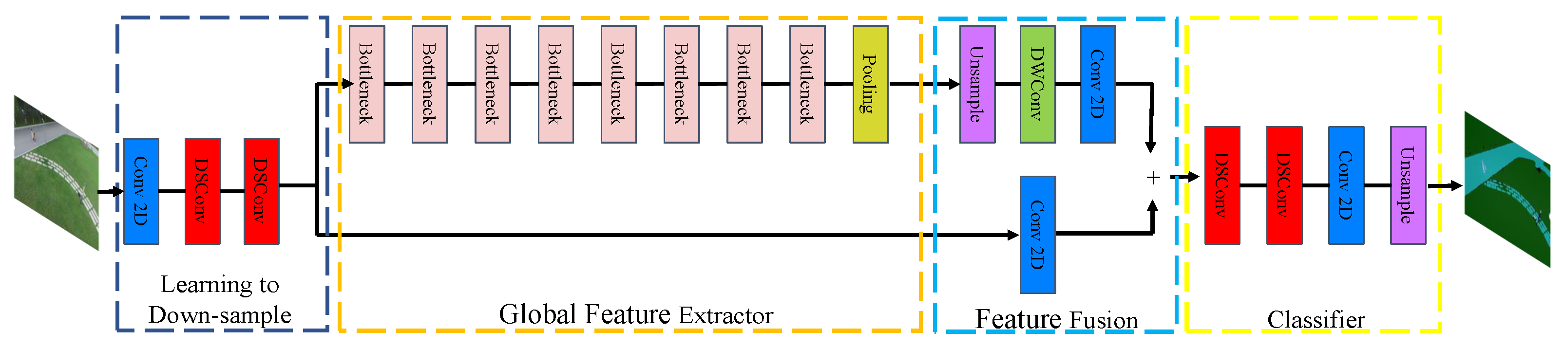
The purpose of image semantic segmentation is to assign every pixel of a picture or video stream taken by a camera with a corresponding category label. When the drone is at a high altitude, the point cloud captured by the LiDAR sensor is sparse, so it is impossible to identify the landing area. Fortunately, the camera can obtain high-resolution images to identify interesting areas. Therefore, through image feature extraction and semantic segmentation of the image data, the position of the landing area in the picture or video stream can be determined, which provides a preliminary recognition for the next step of tracking the landing target area. Since this system needs to process the input images in real-time on the UAV, the real-time performance of the semantic segmentation network should be considered firstly. In our system, we use a lightweight image extraction network to improve the running speed of the network. The model structure of the network is shown in Figure 3, the network model parameters are shown in Table 1, and the specific algorithm flow is as follows.
Firstly, the input image is downsampled by a convolution neural network, and three convolution layers are used to ensure that the low-level features can be effectively shared and used. The first layer is a standard convolution layer, and the other two layers are depthwise separable convolution (DSConv) layers. Different from the standard convolution, in the depth-separable convolution layer, one convolution kernel is only responsible for one channel, and one channel is convolved by only one convolution kernel, so the parameters required for its operation are greatly reduced compared with standard convolution. Although the DSConv has high computational efficiency, there are only three channels in the input image, which makes the advantage of DSConv’s computational speed not reflected at this stage. Therefore, a convolution layer is added before the DSConv layer to improve the input channel of the DSConv. These three layers of networks use a step size of 2 with a batch normalization layer and a Relu activation layer. The convolution kernel of the standard convolution layer and the kernel size of the DSConv layer are both 3 × 3.
Then, the down-sampled image features are input to the global feature extraction module, which aims to capture the global environment information needed for image segmentation. Different from the common semantic segmentation network, it takes a low-resolution tensor as input, that is, the output of the learning down-sampling module as input, and its resolution is one-eighth of the original input image. In order to further speed up the running of the network, we use an efficient bottleneck residual block to build a feature extraction network. This module uses an efficient deep separable convolution, which improves computational efficiency and reduces the number of network parameters and the memory burden. We use the residual connection layer in the bottleneck residual module to fuse the information of each layer. Finally, we add a pyramid pooling module (PPM) at the end of the global feature extraction module. This PPM module can fully aggregate the local information of different sizes obtained under different receptive fields and improve the accuracy and robustness of the network.
The high-level image features extracted by the global feature extraction module are input to the feature fusion module, which processes the features obtained by learning down-sampling through the convolution layer and adds them directly with the high-level features obtained by the global feature extraction module. This fusion method can reduce the computation as much as possible and improve the computation speed of the model without losing the original features and depth features.
The features fused by the feature fusion module are input into the classifier module. This classifier module uses two depth-separable convolution layers and a standard convolution layer. It can output the obtained tensor into a picture with the semantic category label so that the input picture information can be classified to find the preliminary landing area, which provides a basis for the UAV to identify the accurate landing area at low altitude.
We conduct experiments on the PyTorch platform using Python, and our experiments are executed on a workstation with Nvidia 2080 T i GPU with CUDA 11.4 and CuDNN v 8 . We use stochastic gradient decent (SGD) with momentum 0.9 , batchsize 16, and learning rate 0.001 . Because the training data for semantic segmentation are limited, we apply various data augmentation techniques: random resizing between 0.5 and 2, translation/crop, horizontal flip, color channels noise, and brightness. Our model is trained with cross-entropy loss. We train our model for 150 epochs using the Aeroscapes dataset. Our model can achieve 68.88 % mIoU.

4.2. Tracking of Landing Area Based on Image

After the UAV identifies the landing area, it needs to track the landing area in the subsequent image frames, so we design an image-based tracking algorithm for the landing area.
In this system, the output of the landing area search algorithm is used as the input of the landing area tracking algorithm. Four coordinates ( X , Y , W , H ) are used to represent a rectangular frame, where X, Y represent the center pixel coordinates of the rectangular frame, and W, H represent the width and length of the rectangular frame. The rectangular frame contains the area to be tracked. The output of this algorithm is the UAV flight control quantity, and the expression form is the UAV flight target control quantity mapped by coordinate difference (target pixel coordinate–actual pixel coordinate).
Considering the performance of the processor on the UAV and the demand of the whole system for deep learning computing power, the tracking algorithm should be as lightweight as possible. In order to ensure real-time and high accuracy, we build the Siamese network structure to track the image target. In addition, the algorithm also segments the foreground and background of the tracking target area, and the final output results are presented in the form of a mask. The matrix frame is also obtained by rotating rectangle fitting through the mask, which has a good performance for the situation that the geometric shape of the landing area might be irregular.
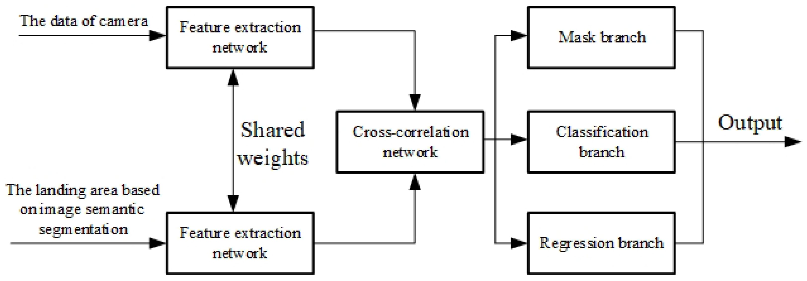
The image-based landing area tracking algorithm uses the Siamese network as the basic architecture of the whole network. The network structure of the Siamese network consists of two identical branches, as shown in the 
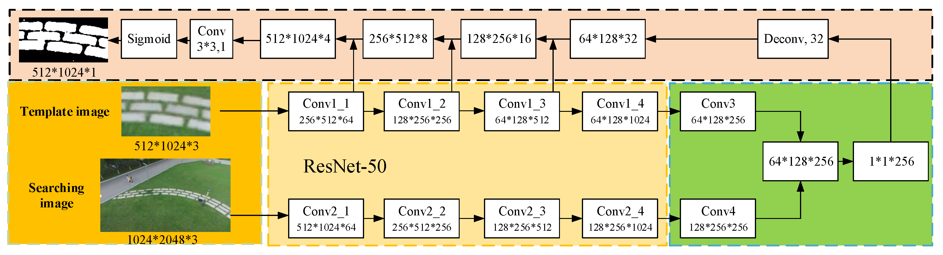
Figure 4. The two branches receive different inputs and then pass through the same feature extraction network to extract high-dimensional image features. In feature extraction, the two branch networks share weights. After that, the high-dimensional features obtained by the branches can be combined with the ground-truth data to construct a loss function. The network can be trained in the way of minimizing the loss so that the network can learn the most similar features of the two branches. The model structure of the network is shown in the Figure 5, and the specific algorithm flow is as follows.
Firstly, the image information of the target region to be tracked is obtained by using the results of the image-based landing region search algorithm through the initial frame to define the target region to be tracked. This part of the image is then input to the ResNet50 backbone network for feature extraction, and the high-dimensional features of the target area to be tracked are generated as the tracking template area. The subsequent image frame input is clipped through the template area range of the first frame to obtain the initial search area. This part is input as a tracking search branch to the ResNet50 branch network with the same parameters as the backbone network for feature extraction, and high-dimensional search area features are obtained.
After obtaining the high-dimensional features of the template branch and the search branch, we carry out cross-correlation between them to obtain the feature map representing the similarity information.
Finally, we use the RPN network to map the similarity feature information map to the original map. There are two branches in the RPN network, namely, the classification branch and regression branch. In addition, a mask branch is added based on these two branches, and the mask of the segmentation field is introduced into the expression of tracking results so that the final result is expressed as the accuracy of the pixel sector, which greatly improves the accuracy of the tracking results. We judge which part of the area has the largest response from the response degree of the network output, which corresponds to the area that best matches the template, that is, the most likely position of the landing area in the next frame.
We conduct experiments on the PyTorch platform using Python, and our experiments are executed on a workstation with Nvidia 2080 T i GPU with CUDA 11.4 and CuDNN v 8 . We train our model for 120 epochs using the VOT-2018 dataset. The loss function is as follows:
L ( θ , ϕ ) = n 1 + y n 2 w h i j log 1 + e c n i j m n i j
where y n ± 1 is the ground-truth binary label, c n is a pixel-wise ground-truth mask whose size is w × h , and c n i j ± 1 is the label corresponding to pixel ( i , j ) of the object mask in the n-th candidate.

4.3. 3D Environment Modeling Based on Point Cloud

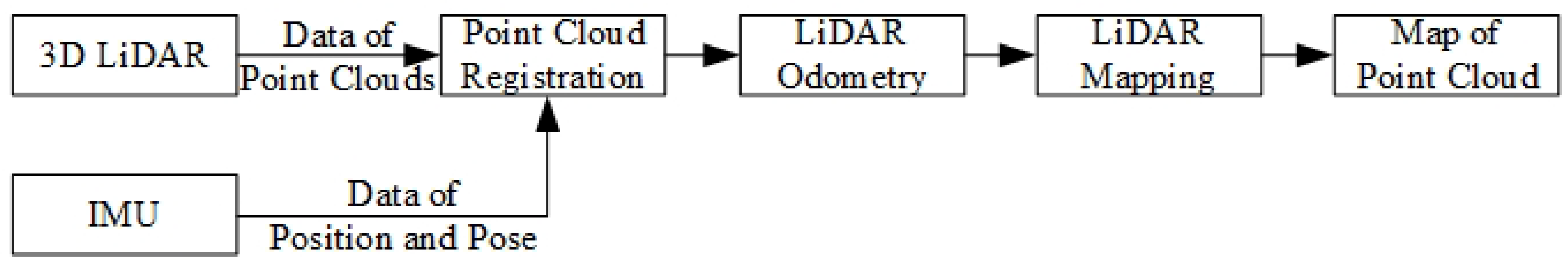
When the UAV identifies the approximate landing area, we guide the UAV towards the landing area, and then map the environment of the candidate landing area by 3D LiDAR carried by the UAV to obtain the terrain information of the landing area. Because the UAV needs accurate spatial information and needs to establish an accurate 3D map for landing point calculation, we use 3D LiDAR as the main sensor to create a 3D point cloud map of the environment. Considering that the landing environment of the UAV is an outdoor open area, there may be insufficient environmental features in the surrounding environment, which makes the motion estimation only by LiDAR fail. Therefore, the algorithm combines LiDAR odometer and IMU data to provide the spatial position information of the UAV motion, enhancing the robustness and accuracy of the UAV motion estimation. The algorithm framework of 3D environment modeling is shown in Figure 6.
Because the LiDAR sensor scans the surrounding environment all the time, when the UAV moves, the laser point itself has a certain motion state, which makes the point cloud of one frame of LiDAR distort, caused by motion. In order to obtain the correct environmental point cloud information, it is necessary to dedistort the LiDAR point cloud. To remove the motion distortion of LiDAR point clouds, it is necessary to compensate for the motion change in LiDAR point clouds relative to the beginning of the laser frame. In this system, the motion change obtained by IMU is used to compensate for the motion of the LiDAR point clouds to obtain the point cloud data without motion distortion.
In order to calculate the motion pose of the UAV, we need to obtain the attitude transformation relationship between consecutive frames, so as to estimate the motion state. Considering the real-time requirement of the system, we use the feature points of the point cloud instead of the whole frame point cloud to solve the pose estimation. In order to improve the accuracy of pose estimation, for point cloud feature extraction, we extract the plane features of point clouds. The plane features in the point cloud are extracted, and the curvature of the local point cloud is calculated by using the surrounding points of the current point. The calculation method is as follows:
c = 1 | M | × X ( k , i ) L j M , j i X ( k , i ) L X ( k , j ) L
where X ( k , i ) L is the i point in the laser coordinate system in the k frame point cloud, M is the surrounding point set corresponding to this point, and X ( k , j ) L is the J point in the surrounding point set M. The large curvature points are considered as edge points, and the small curvature points are considered as plane points, so the local point clouds with small curvature are selected as plane features.
After extracting the features of point clouds in each frame, we need to match the features of point clouds between different frames, so as to find the pose transformation between the two frames of point clouds. We transform the feature points of the previous frame point cloud into the current frame coordinate system and find the nearest three points in the previous frame point cloud: X ( k , j ) , X ( k , l ) , and X ( k , m ) . The three points form a planar block, thus completing the feature matching between the current frame and the previous frame. Then, according to the matched surface blocks, we find the corresponding point–plane distance, and the calculation method is as follows:
d = X i L X j L × X j L X k L × X j L X m L X j L X k L × X j L X m L
According to the calculated point–plane distance d, the point–plane distance constraint is constructed. Based on this, the least square problem of point cloud feature point matching is established, which optimizes the relative pose change between laser frames and outputs the motion state of the UAV.
After the laser odometer is obtained, the point clouds can be spliced according to the position and orientation relationship of the point cloud frames. However, due to the interframe motion, the estimated odometer will have accumulated errors, which makes the error of point cloud mosaic increase only by using the odometer. Therefore, it is necessary to register the current frame point cloud with the global point cloud map, so as to eliminate the accumulated errors of the odometer and establish a globally consistent point cloud map. In order to reduce the amount of point cloud data, point cloud space is divided into voxels: only point clouds within a certain voxel space are considered, and unimportant point clouds in the environment are ignored. Then, a local voxel map is established according to odometer information by registering the plane features in the local voxel map with the global voxel map, accurate pose changes are obtained, and the accumulated errors existing in the front-end odometer are eliminated. According to the optimized pose, point clouds are spliced to obtain an accurate and globally consistent 3D environmental point cloud map.

4.4. 3D Environment Segmentation Based on Image and Point Cloud Fusion

Although the method based on semantic features of 2D images can estimate the position of the landing area roughly, the results of feature extraction may have some errors, and it is often difficult to accurately estimate the accurate 3D position of the landing area. If the UAV wants to complete the autonomous landing task more stably and safely, it needs to obtain accurate 3D position information of the landing area, so this system needs to realize 3D environment segmentation through point cloud information. The current 3D environment segmentation method based on point cloud needs high memory and computing power; however, our UAV has a limited onboard payload and cannot carry a GPU with stronger computing power. Therefore, this system does not use the deep learning method to directly extract semantic features of point clouds but indirectly obtains point cloud data with semantic tags through the image semantic segmentation method.
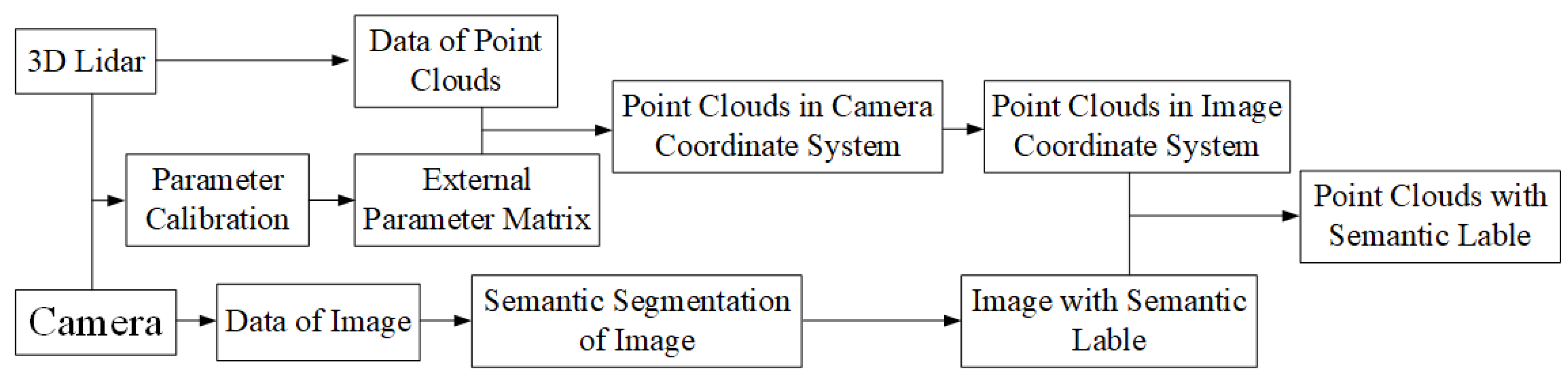
As shown in Figure 7, firstly, the image semantic segmentation method proposed in the aforementioned section is used to segment the image semantically. Then, the point cloud data of LiDAR are projected into the camera coordinate system through the transformation matrix between the camera and LiDAR, and then they are projected into the image coordinate system of the camera through the internal reference coordinate system of the camera. Since we have obtained the camera image with pixel-by-pixel semantic category labels, the projected point cloud also has the semantic information from the image, and the semantic category label corresponding to the image pixel is the semantic label of the point. Finally, the point cloud data with semantic labels are obtained by transforming the point cloud back to the LiDAR coordinate system.

4.5. Real-Time Landing Point Search

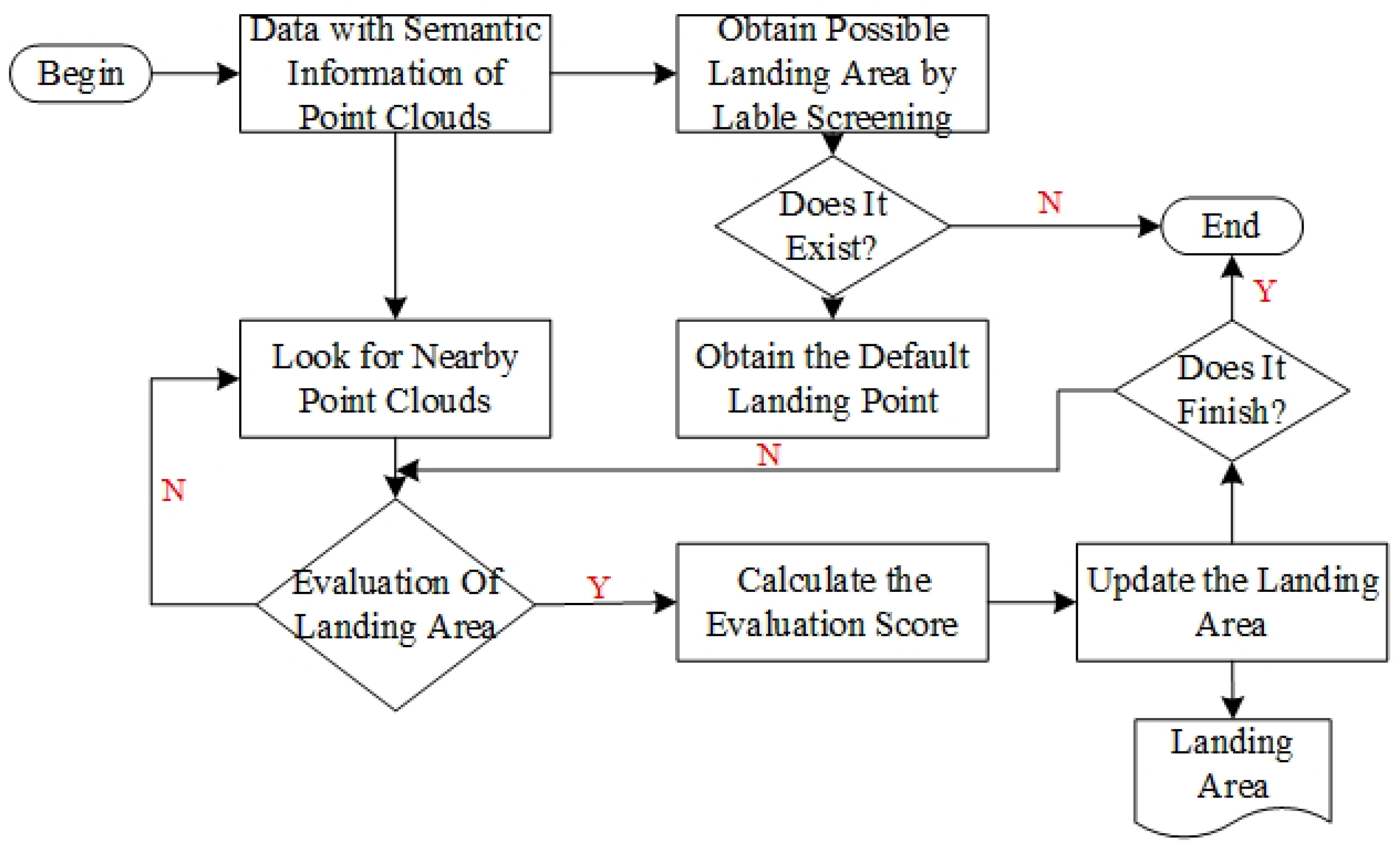
We can obtain the candidate landing area by screening the semantic tags of the point cloud. However, considering the robustness of semantic feature extraction and other factors, not all the candidate landing areas can be used as landing areas for the UAV. The area suitable for the UAV landing should also have the following characteristics: Firstly, the landing area should be flat enough without large bumps or depressions. Secondly, the landing area should be horizontal enough. If it lands on a slope, the drone may not stop smoothly. Thirdly, the re-landing area should be large enough for the UAV to land and far enough from the boundary of the area. Because our UAV is a vertical take-off and landing drone, there should be no obstacles above the landing area to avoid possible collision during landing. Finally, because the UAV makes contact with the ground through the landing gear, the terrain structure of the landing area should remain stable when the landing gear of the UAV makes contact with it. In order to ensure the correctness and stability of the algorithm, we add the geometric features of the point cloud as constraints based on semantic features to achieve accurate detection and recognition of the landing area.
The structure of the algorithm is shown in Figure 8. First, we search the terrain on the ground in the point cloud map with semantic labels, select the area where the most suitable terrain is located as the possible landing area, and extract the corresponding point cloud in this area. According to the difficulty of the UAV landing in different terrain environments, the priority of the terrain is usually paved ground, hard land, grass land, and sand. However, even in suitable terrain, not every position is suitable for landing the UAV. There may also be slopes, bulges, depressions, etc., in the actual landable environment, such as paved ground, which are often not conducive to the UAV landing. However, the above-mentioned methods based on deep learning have difficulty identifying these conditions accurately and stably, so we use the geometric features of point clouds as constraints to select the most suitable landing site. Firstly, we down-sample the point cloud and obtain a sparse point cloud map of the possible landing areas. We assume that the final landing area of the UAV is circular, and each point in the point cloud is set as the center point of the possible candidate landing area of the UAV. For each possible center point, we extract the nearest point cloud corresponding to the point in the original point cloud. The point cloud can reflect the terrain of the candidate landing area. We use geometric methods to calculate the attributes of this part of the point cloud to estimate the terrain of the candidate landing area. First of all, we count the number of points in the point cloud of the candidate landing area. If the number of point clouds is not enough, it means that this part of the area has not been fully detected or there are terrains such as water surface that are not suitable for landing. Then, we calculate the standard deviation of the zcoordinate value of each point in the point cloud. If the standard deviation is too large, it means that the candidate landing area may be inclined or uneven, which is also unsuitable for the landing area. Finally, in order to further determine whether the candidate landing area is a horizontal plane, we try to use the RANSAC algorithm [32] to fit the plane from the point cloud. If the plane cannot be fitted or the slope of the fitted plane is too large, it means that the candidate landing area is not suitable as the landing area. We use the angle between the plane normal and the z coordinate axis to calculate the slope of the plane, namely:
α = arccos v u p T n
where v u p T = ( 0 , 0 , 1 ) is the vector of the z axis, n is the vector of the plane normal fitted by the RANSAC algorithm, and α is the slope of the plane.
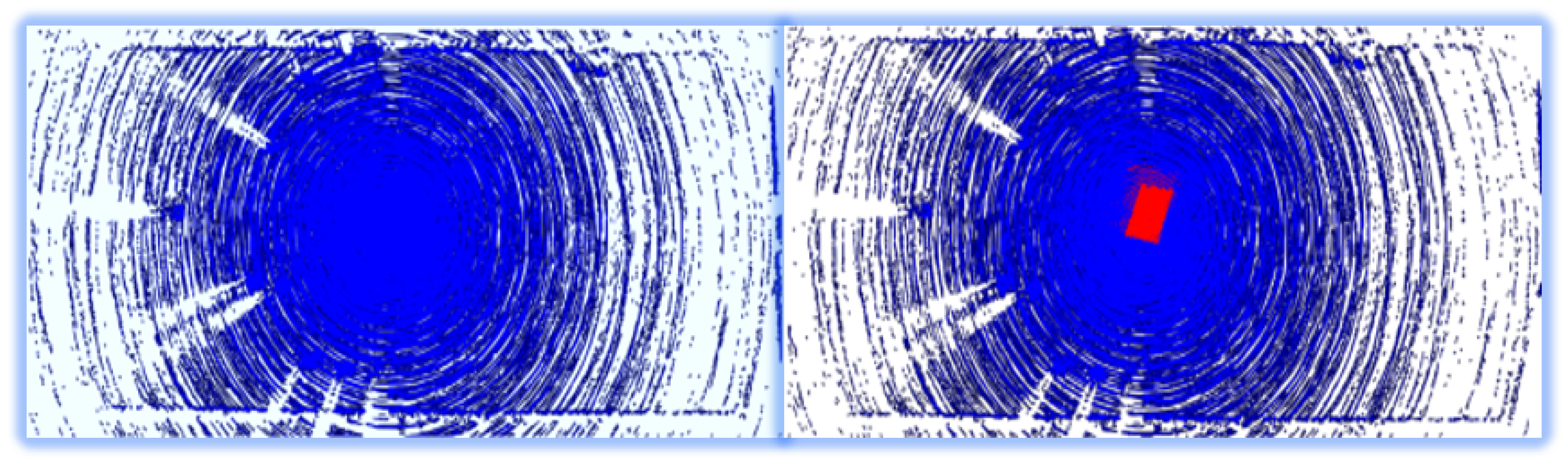
Because the UAV makes contact with the ground through the landing gear during take-off and landing, the contact between the ground and the landing gear is an important factor for the UAV to maintain stability when landing. On the premise that the central landing site is determined, we assume that there are eight possible landing directions for the UAV. Therefore, there are four possible contact situations between the landing gear of the UAV and the ground. For each possible case, we can calculate the contact point between the landing gear of the UAV and the ground, and then calculate the torque of the UAV when landing. The smaller the T, the more stable the UAV when landing. In order to calculate the best landing site for the UAV landing, we calculate a score for each candidate landing area by quantitative calculation. The score calculation formula is:
S c o r e = 1 σ z α T
where σ z is the standard deviation of the z coordinate value of each point in the landing area, α is the slope of the fitting plane of the landing area, and T is the stability of the UAV when landing. For all candidate landing sites, we choose the point with the largest score as the best landing area to provide landing area position information for autonomous landing of the UAV.

5. Experiment

5.1. Experiment in Simulation Environment

In order to verify the effectiveness of each part of the system, we build a virtual simulation scene and a UAV simulation platform equipped with virtual sensors by using gazebo simulation tools. The simulation environment is shown in Figure 9.
After we build the simulation environment, we can perform a qualitative test on the effectiveness of the system algorithm in the simulation environment. The Figure 10 shows the experimental results of semantic segmentation and tracking of the landing area based on images during the UAV landing from high altitude to low altitude. The Figure 11 shows the results of 3D environment modeling based on point cloud and semantic segmentation of 3D point cloud fused with image semantic information in the descending process of the UAV. In the simulation environment, we also conducted 30 automatic landing tests. As shown in Figure 12, the first figure (a) shows the 5 m high landing area platform built in the gazebo simulation environment. The remaining three figures (b, c, d) show the autonomous landing trajectories of the UAV at three different initial positions. In the tests, the absolute value of the distance between the actual landing point of the drone and the center point of the landing area was measured. The statistical data of the average and variance are shown in Table 2. In the process of simulation test, the UAV can obtain the recognition and tracking results of the landing area in real-time and can be guided to realize autonomous landing.

5.2. Experiment in Real Environment

After we verify the whole system in the simulation environment, we test it in the real environment. We perform experiments of image-based descent area searching and tracking, point cloud-based 3D environment modeling, and point cloud-based 3D environment segmentation. The average speed of the whole algorithm is 10 Hz, which can satisfy a real-time system.
For the landing area searching of the image, we test our algorithm on a M600 Pro UAV in a real environment. The UAV performs real-time semantic segmentation to identify the landing area and send the pixel coordinates corresponding to the 3D environment semantic segmentation based on point clouds. It is easy to obtain the category information of each 3D laser point through the image and the external parameter between the LiDAR and the camera. According to the semantic segmentation results of the high-altitude images from the UAV, the target tracking based on images is realized in the landing area, which makes the UAV land slowly from high altitude to low altitude. The results of searching and tracking the landing area based on the image are shown in the Figure 13, which shows that the landing area can be tracked well.
For the 3D environment modeling of the point cloud, we collect the actual environment data on M600 Pro UAV, and then process the collected LiDAR point cloud data to establish the 3D model of the actual environment. The actual environment model is shown in Figure 14. In this figure, we can see that the surrounding environment is modeled by the landing area recognition system.
The accurate recognition results of the landing area based on the 3D semantic environment model of landing area are shown in Figure 15. From the figure, it can be seen that the landing area recognition algorithm gives the position of the landing area (red part). The area is located in the suitable landing area with a slope of 3.4 and a roughness of 0.29 , which meet the requirements of the UAV for a landing site. Therefore, the algorithm proposed in this paper can also accurately identify the landing site according to the 3D semantic environment model of the landing area in a real environment.
In order to further verify the effectiveness of the recognition system, we attach the terrain recognition system module to a middle-size unmanned helicopter for practical verification. As shown in Figure 16, the top figure shows the location where the landing area recognition system is installed in the unmanned helicopter, and the bottom figure shows the process from take-off to landing of the unmanned helicopter. The red trajectory in the bottom figure shows the flight trajectory of the unmanned helicopter and the yellow area shows the location of the landing area of the unmanned helicopter. From the bottom figure, it can be seen that our proposed method can accurately identify the landing area on different UAV platforms in a real environment.

6. Conclusions

In this paper, a multi-sensor UAV landing area recognition system is designed to realize the robust and accurate recognition and estimation of suitable landing area. Firstly, we determine the approximate position of the possible landing area by semantic segmentation of the image data taken by the camera. Then, the image tracking algorithm continuously tracks the area and guides the UAV to fly to the possible landing area, and then fuses the data of LiDAR, IMU, and camera sensors to obtain the accurate 3D position information of the landing area. We also combine the point cloud semantic features with the point cloud features extracted by traditional geometric methods to further improve the accuracy and robustness of the algorithm. Both simulation and real experiments demonstrated the effectiveness of the proposed method. In the future, we will carry out more experiments in much more challenging environments.

Author Contributions

Conceptualization, Z.F.; methodology, F.L. and J.S.; software, F.L., J.S. and B.X.; validation, F.L.; formal analysis, F.L.; investigation, F.L.; writing—original draft preparation, F.L. and Z.F.; writing—review and editing, F.L. and Z.F.; visualization, F.L.; supervision, Z.F.; project administration, Z.F. All authors have read and agreed to the published version of the manuscript.

Funding

This work was supported by National Natural Science Foundation of China (62073066, U20A20197), Science and Technology on Near-Surface Detection Laboratory (6142414200208), the Fundamental Research Funds for the Central Universities (N2226001), and Major Special Science and Technology Project of Liaoning Province (No.2019JH1/10100026), and Aeronautical Science Foundation of China (No. 201941050001).

Institutional Review Board Statement

Not applicable.

Informed Consent Statement

Not applicable.

Data Availability Statement

Not applicable.

Conflicts of Interest

The authors declare no conflict of interest. The funders had no role in the design of the study.

References

  1. Sarkisov, Y.S.; Yashin, G.A.; Tsykunov, E.V.; Tsetserukou, D. DroneGear: A Novel Robotic Landing Gear With Embedded Optical Torque Sensors for Safe Multicopter Landing on an Uneven Surface. IEEE Robot. Autom. Lett. (RAL) 2018, 3, 1912–1917. [Google Scholar] [CrossRef]
  2. Saripalli, S. Vision-based autonomous landing of an helicopter on a moving target. In Proceedings of the AIAA Guidance, Navigation, and Control Conference, Chicago, IL, USA, 10–13 August 2009; p. 5660. [Google Scholar]
  3. Majji, M.; Davis, J.; Doebbler, J.; Junkins, J.; Macomber, B.; Vavrina, M.; Vian, J. Terrain mapping and landing operations using vision based navigation systems. In Proceedings of the AIAA Guidance, Navigation, and Control Conference, Portland, OR, USA, 8–11 August 2011; p. 6581. [Google Scholar]
  4. Weiss, S.; Achtelik, M.; Kneip, L.; Scaramuzza, D.; Siegwart, R. Intuitive 3D maps for MAV terrain exploration and obstacle avoidance. J. Intell. Robot. Syst. 2011, 61, 473–493. [Google Scholar] [CrossRef] [Green Version]
  5. Wendel, A.; Maurer, M.; Graber, G.; Pock, T.; Bischof, H. Dense reconstruction onthe-fly. In Proceedings of the Computer Vision and Pattern Recognition (CVPR), Providence, RI, USA, 16–21 June 2012; pp. 1450–1457. [Google Scholar]
  6. Pizzoli, M.; Forster, C.; Scaramuzza, D. REMODE: Probabilistic, monocular dense reconstruction in real time. In Proceedings of the 2014 IEEE International Conference on Robotics and Automation (ICRA), Hong Kong, China, 31 May–5 June 2014; pp. 2609–2616. [Google Scholar]
  7. Faessler, M.; Fontana, F.; Forster, C.; Mueggler, E.; Pizzoli, M.; Scaramuzza, D. Autonomous, vision-based flight and live dense 3D mapping with a quadrotor micro aerial vehicle. J. Field Robot. 2016, 33, 431–450. [Google Scholar] [CrossRef]
  8. Barber, B.; McLain, T.; Edwards, B. Vision-based landing of fixed-wing miniature air vehicles. J. Aerosp. Comput. Inf. Commun. 2009, 6, 207–226. [Google Scholar] [CrossRef]
  9. Millet, P.; Ready, B.; McLain, T. Vision-based precision landings of a tailsitter UAV. In Proceedings of the AIAA Guidance, Navigation, and Control Conference, Chicago, IL, USA, 10–13 August 2009; p. 5680. [Google Scholar]
  10. Desaraju, V.R.; Michael, N.; Humenberger, M.; Brockers, R.; Weiss, S.; Nash, J.; Matthies, L. Vision-based landing site evaluation and informed optimal trajectory generation toward autonomous rooftop landing. Auton. Robot. 2015, 39, 445–463. [Google Scholar] [CrossRef]
  11. Silva, M.F.; Cerqueira, A.S.; Vidal, V.F.; Honório, L.M.; Santos, M.F.; Oliveira, E.J. Landing area recognition by image applied to an autonomous control landing of VTOL aircraft. In Proceedings of the 2017 18th International Carpathian Control Conference (ICCC), Sinaia, Romania, 28–31 May 2017; pp. 240–245. [Google Scholar]
  12. Cheng, H.W.; Chen, T.L.; Tien, C.H. Motion Estimation by Hybrid Optical Flow Technology for UAV Landing in an Unvisited Area. Sensors 2019, 19, 1380. [Google Scholar] [CrossRef] [PubMed] [Green Version]
  13. Lee, M.F.R.; Nugroho, A.; Le, T.T.; Bahrudin; Bastida, S.N. Landing area recognition using deep learning for unammaned aerial vehicles. In Proceedings of the 2020 International Conference on Advanced Robotics and Intelligent Systems (ARIS), Taipei, Taiwan, 19–21 August 2020; pp. 1–6. [Google Scholar]
  14. Forster, C.; Faessler, M.; Fontana, F.; Werlberger, M.; Scaramuzza, D. Continuous on-board monocular-vision-based elevation mapping applied to autonomous landing of micro aerial vehicles. In Proceedings of the IEEE International Conference on Robotics and Automation (ICRA), Seattle, WA, USA, 26–30 May 2015; pp. 111–118. [Google Scholar]
  15. Wubben, J.; Fabra, F.; Calafate, C.T.; Krzeszowski, T.; Marquez-Barja, J.M.; Cano, J.C.; Manzoni, P. Accurate landing of unmanned aerial vehicles using ground pattern recognition. Electronics 2019, 8, 1532. [Google Scholar] [CrossRef] [Green Version]
  16. Templeton, T.; Shim, D.H.; Geyer, C.; Sastry, S.S. Autonomous Vision-based Landing and Terrain Mapping Using an MPC-controlled Unmanned Rotorcraft. In Proceedings of the IEEE International Conference on Robotics and Automation (ICRA), Roma, Italy, 10–14 April 2007; pp. 1349–1356. [Google Scholar]
  17. Shanggang Lin, M.A.G.; Lambert, A.J. Monocular vision-based real-time target recognition and tracking for autonomously landing an UAV in a cluttered shipboard environment. Auton. Robot. 2017, 41, 881–901. [Google Scholar]
  18. García-Pulido, J.; Pajares, G.; Dormido, S.; de la Cruz, J. Recognition of a landing platform for unmanned aerial vehicles by using computer vision-based techniques. Expert Syst. Appl. 2017, 76, 152–165. [Google Scholar] [CrossRef]
  19. Theodore, C.; Rowley, D.; Ansar, A.; Matthies, L.; Goldberg, S.; Hubbard, D.; Whalley, M. Flight trials of a rotorcraft unmanned aerial vehicle landing autonomously at unprepared sites. In Proceedings of the Annual Forum Proceedings-American Helicopter Society, Phoenix, AZ, USA, 9–11 May 2006; p. 1250. [Google Scholar]
  20. Garg, M.; Kumar, A.; Sujit, P. Terrain-based landing site selection and path planning for fixed-wing UAVs. In Proceedings of the International Conference on Unmanned Aircraft Systems (ICUAS), Denver, CO, USA, 9–12 June 2015; pp. 246–251. [Google Scholar]
  21. Park, J.; Kim, Y.; Kim, S. Landing Site Searching and Selection Algorithm Development Using Vision System and its Application to Quadrotor. IEEE Trans. Control Syst. Technol. 2015, 23, 488–503. [Google Scholar] [CrossRef]
  22. Mittal, M.; Valada, A.; Burgard, W. Vision-based autonomous landing in catastrophe-struck environments. In Proceedings of the International Symposium on Safety (SSRR), Philadelphia, PA, USA, 6–8 August 2018. [Google Scholar]
  23. Jiang, M. Binocular Stereo Vision Intelligent Control Framework for the Landing Position of Quadrotor UAV Based on Fuzzy Control. In Proceedings of the 2021 6th International Conference on Communication and Electronics Systems (ICCES), Coimbatore, India, 8–10 July 2021; pp. 1348–1352. [Google Scholar]
  24. Cui, T.; Guo, C.; Liu, Y.; Tian, Z. Precise Landing Control of UAV Based on Binocular Visual SLAM. In Proceedings of the 2021 4th International Conference on Intelligent Autonomous Systems (ICoIAS), Wuhan, China, 14–16 May 2021; pp. 312–317. [Google Scholar]
  25. Maturana, D.; Scherer, S. 3D Convolutional Neural Networks for landing zone detection from LiDAR. In Proceedings of the IEEE International Conference on Robotics and Automation (ICRA), Seattle, WA, USA, 26–30 May 2015; pp. 3471–3478. [Google Scholar]
  26. Mango, D.; Opromolla, R.; Schmitt, C. Hazard detection and landing site selection for planetary exploration using LIDAR. In Proceedings of the 2020 IEEE 7th International Workshop on Metrology for AeroSpace (MetroAeroSpace), Pisa, Italy, 22–24 June 2020; pp. 392–397. [Google Scholar]
  27. Ikura, M.; Miyashita, L.; Ishikawa, M. Real-time Landing Gear Control System Based on Adaptive 3D Sensing for Safe Landing of UAV. In Proceedings of the 2020 IEEE/SICE International Symposium on System Integration (SII), Honolulu, HI, USA, 12–15 January 2020; pp. 759–764. [Google Scholar]
  28. Ikura, M.; Miyashita, L.; Ishikawa, M. Stabilization System for UAV Landing on Rough Ground by Adaptive 3D Sensing and High-Speed Landing Gear Adjustment. J. Robot. Mechatron. 2021, 33, 108–118. [Google Scholar] [CrossRef]
  29. Kalinov, I.; Safronov, E.; Agishev, R.; Kurenkov, M.; Tsetserukou, D. High-precision UAV localization system for landing on a mobile collaborative robot based on an IR marker pattern recognition. In Proceedings of the 2019 IEEE 89th Vehicular Technology Conference (VTC2019-Spring), Kuala Lumpur, Malaysia, 28 April–1 May 2019; pp. 1–6. [Google Scholar]
  30. Tsintotas, K.A.; Bampis, L.; Taitzoglou, A.; Kansizoglou, I.; Gasteratos, A. Safe UAV landing: A low-complexity pipeline for surface conditions recognition. In Proceedings of the 2021 IEEE International Conference on Imaging Systems and Techniques (IST), New York, NY, USA, 24–26 August 2021; pp. 1–6. [Google Scholar]
  31. Chen, L.; Yuan, X.; Xiao, Y.; Zhang, Y.; Zhu, J. Robust Autonomous Landing of UAV in Non-Cooperative Environments based on Dynamic Time Camera-LiDAR Fusion. arXiv 2020, arXiv:abs/2011.13761. [Google Scholar]
  32. Fischler, M.A.; Bolles, R.C. Random sample consensus: A paradigm for model fitting with applications to image analysis and automated cartography. Commun. ACM 1981, 24, 381–395. [Google Scholar] [CrossRef]
Figure 1. The hardware system.
Drones 06 00118 g001
Figure 2. The main structure block diagram of the system.
Drones 06 00118 g002
Figure 3. The model structure of the image semantic segmentation network.
Drones 06 00118 g003
Figure 4. The model structure of the Siamese network.
Drones 06 00118 g004
Figure 5. The model structure of the image tracking network.
Drones 06 00118 g005
Figure 6. The algorithm framework of 3D environment modeling.
Drones 06 00118 g006
Figure 7. The algorithm framework of 3D environment semantic segmentation.
Drones 06 00118 g007
Figure 8. The algorithm framework of 3D environment modeling.
Drones 06 00118 g008
Figure 9. The simulation environment. The picture on the left is the UAV simulation platform equipped with virtual sensors, and the picture on the right is the virtual simulation scene.
Drones 06 00118 g009
Figure 10. The experimental results of semantic segmentation and tracking of the landing area based on images during the UAV landing from high altitude to low altitude.
Drones 06 00118 g010
Figure 11. The raw point cloud data (Left). The results of 3D environment modeling based on point cloud and semantic segmentation of 3D point cloud fused with image semantic information (Right).The red bounding box represents the tracking result of the landing area.
Drones 06 00118 g011
Figure 12. The landing area in the simulation environment (a) and the autonomous landing trajectory of the UAV (bd). The yellow box is the landing area. The blue box is the initial position and the red box is the landing point.
Drones 06 00118 g012
Figure 13. The results of searching and tracking the landing area based on the image. The landing area is a square whose side length is 1 m.
Drones 06 00118 g013
Figure 14. The actual environment model.The red bounding box in the figure is the paved ground which we preset. We use the paved ground to verify the effectiveness of the algorithm, and the picture shows the paved ground in different states across different sensors and stages.
Drones 06 00118 g014
Figure 15. The accurate recognition results of landing site based on the 3D semantic environment model of landing area.
Drones 06 00118 g015
Figure 16. The orange areas are the results of recognition of the landing area, and the green lines are the results of the tracking of the landing area (Left). The red box represents the location of the landing area recognition system in the unmanned helicopter (Right-Top). The red trajectory represents the process from take-off to landing of the unmanned helicopter and the yellow area represents the landing area (Right-Bottom).
Drones 06 00118 g016
Table 1. The semantic segmentation network uses standard convolution (Conv2D), depthwise separable convolution (DSConv), residual bottleneck blocks (bottleneck), a pyramid pooling module (PPM), and a feature fusion module block (FFM). Parameters channels, stride, and n represent number of output channels, stride parameter, and number of times block, respectively.
InputBlockChannelsStriden
1024 × 2048 × 3Conv2D3221
512 × 1024 × 32DSConv4821
256 × 512 × 48DSConv6421
128 × 256 × 64bottleneck6423
64 × 128 × 64bottleneck9623
32 × 64 × 96bottleneck12813
32 × 64 × 128PPM128--
32 × 64 × 128FFM128--
128 × 256 × 128DSConv12812
128 × 256 × 11Conv2D12811
Table 2. The distance between the actual landing point of the drone and the center point of the landing area (30 times).
Average Value (/m)Variance (/m2)
The distance between the two0.02200.02369
Publisher’s Note: MDPI stays neutral with regard to jurisdictional claims in published maps and institutional affiliations.

