


RF Source Localization Using Multiple UAVs through a Novel Geometrical RSSI Approach

Abstract
:1. Introduction
2. Related Work
- Ability to do localization in GPS-denied environments.
- Ability to do localization without knowing the output power of the target and without the need for time synchronization between the transceiver and receiver antennas
- For environments with weak GPS signals, a novel geometry-based localization method has been developed.
- Since the receiving antennas are on the UAVs, a method has been developed that will make it possible to detect the target location more precisely by increasing the distances between the UAVs.
- An augmented point on the sphere is calculated where the line passing through this point and sphere center also passes through the target position.
3. Materials and Method
- There is no prior information on the target’s location.
- Signal strength is all that is measured by UAVs; there is no time stamp or other useful information in the signal. There is no direction-finding hardware on board.
- There is always a clear line of sight between the UAVs and the target.
- There are no communication limitations; UAVs may send and receive data without losing information.
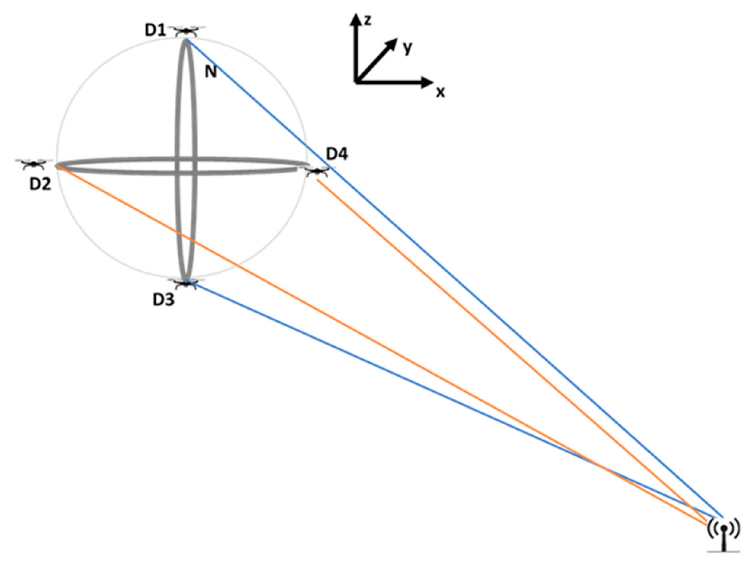
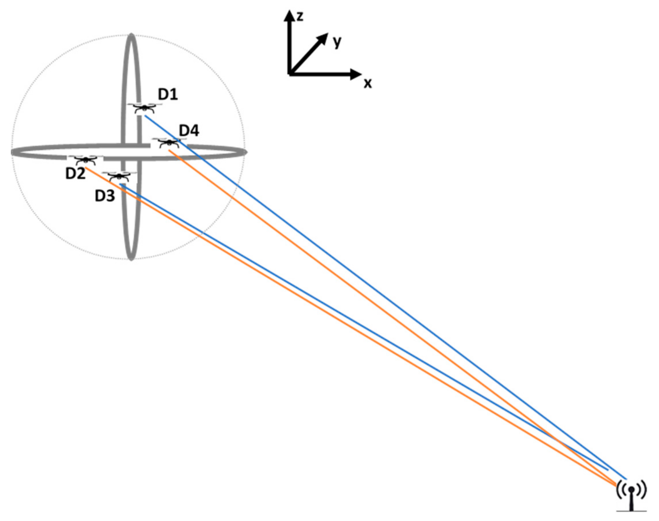
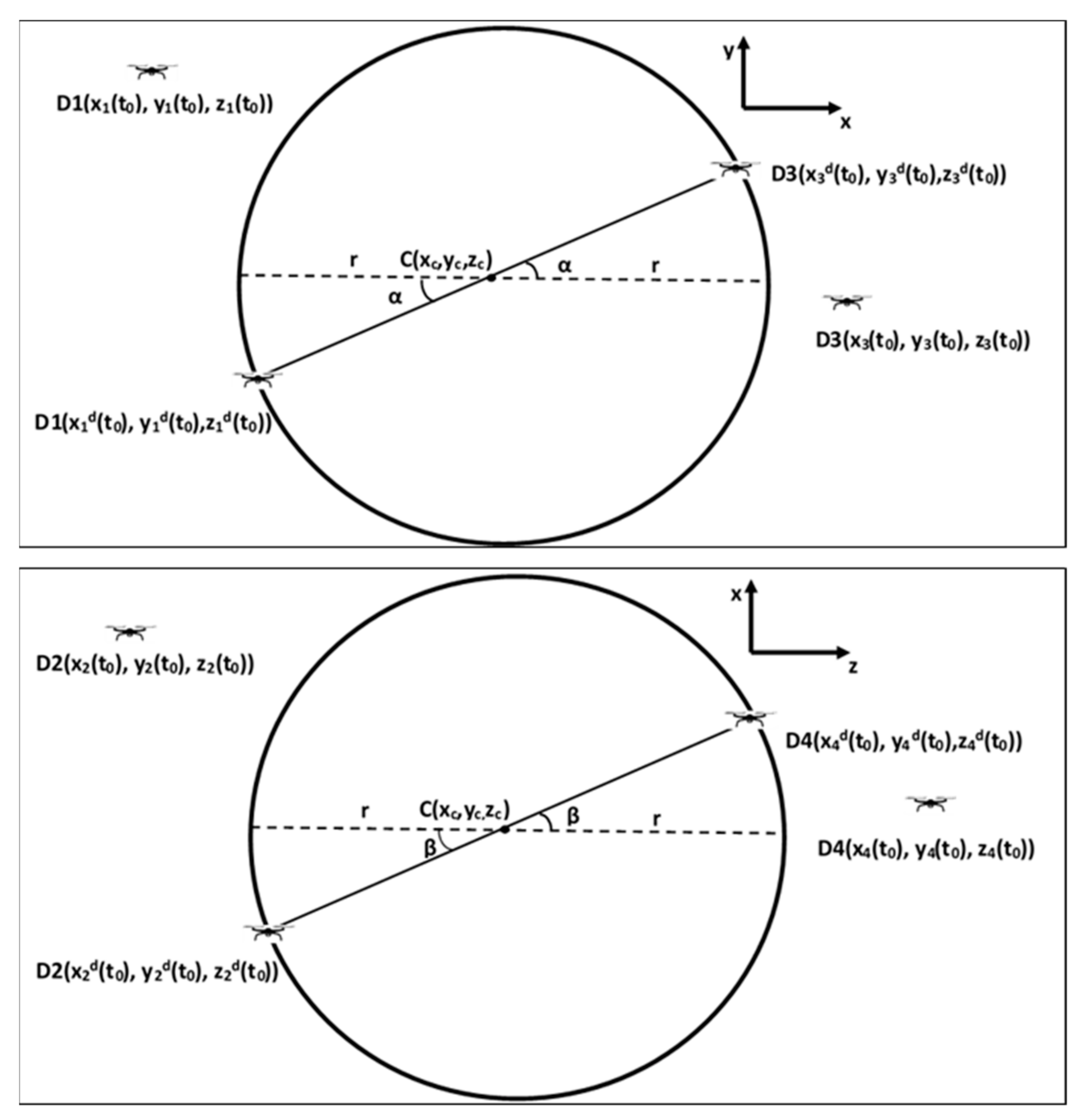
3.1. Desired Initial Posture Derivation of Four UAVs
3.2. Rotating Angle Calculation
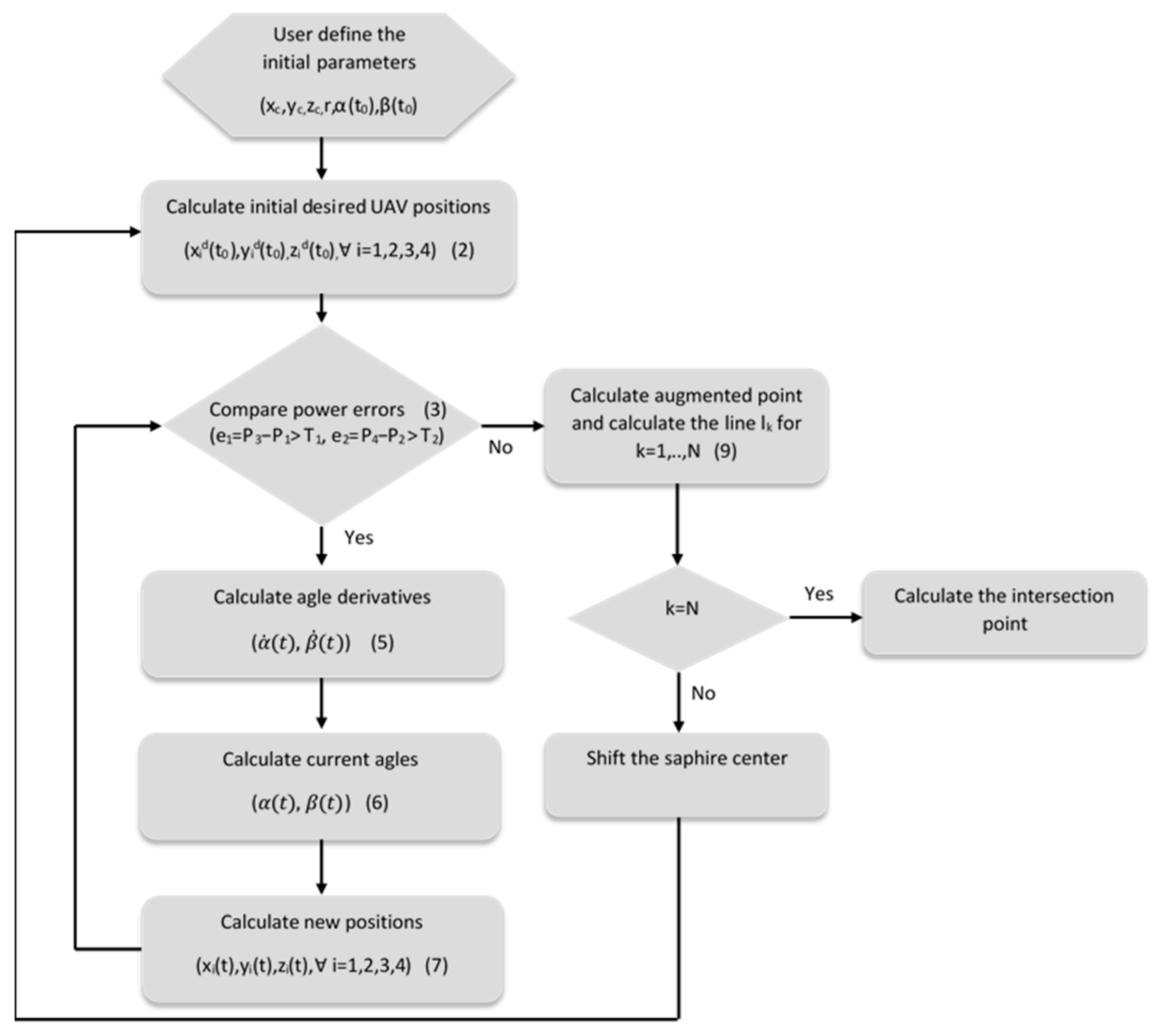
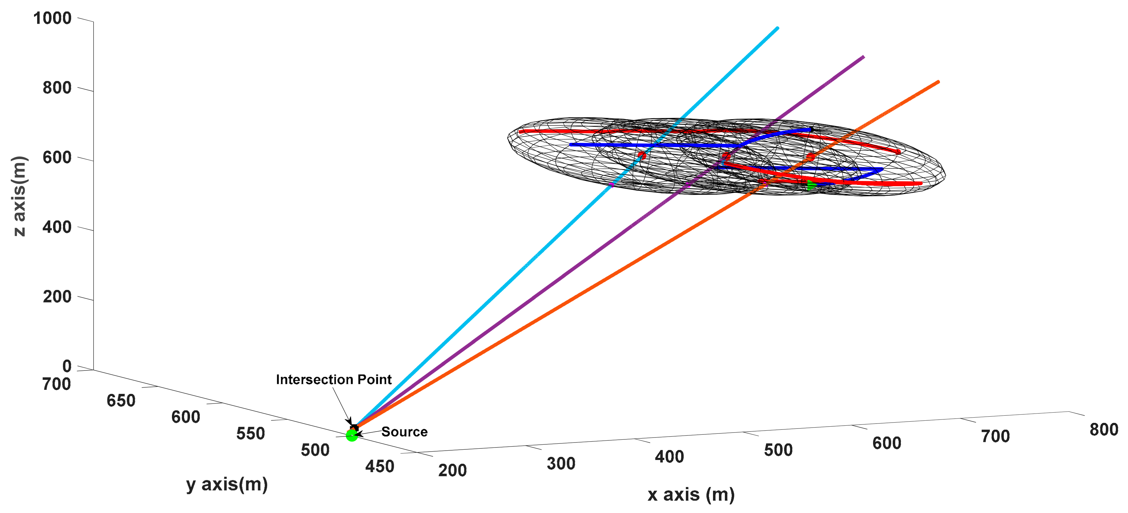
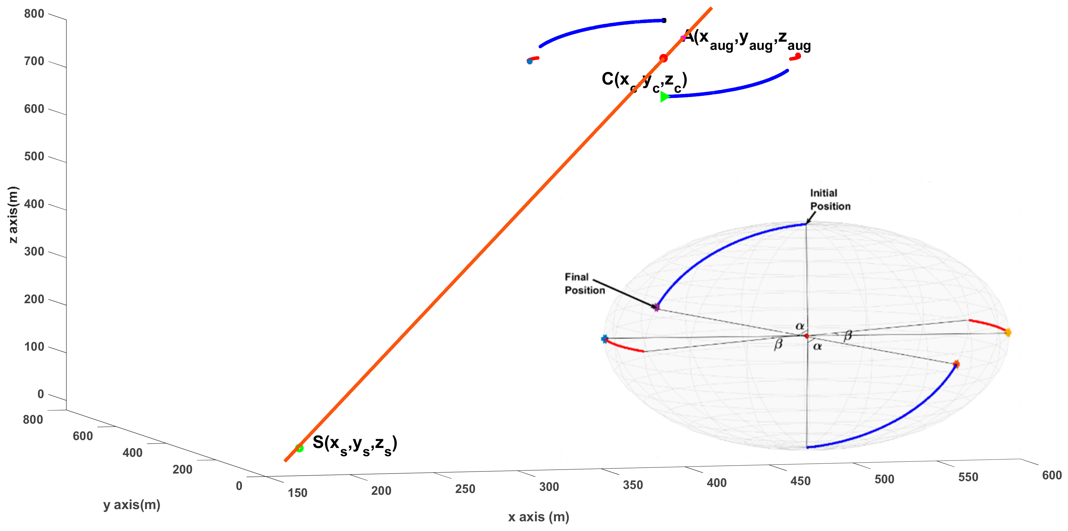
3.3. Augmented Point and Direction Calculation
| Algorithm 1: Minimum distance to lines calculation (). |
| 1: Set n = length of line segments, N = number of line segments; P is a very large constant |
| 2: ; |
| 3: for ; |
| 4: for |
| 5: if |
| 6: |
| 7: for |
| 8: for |
| 9: |
| 10: if |
| 11: |
| 12: end if |
| 13: end for |
| 14: end for |
| 15: , |
| 16: |
| 17: end for |
| 18: end for |
| 19: end for |
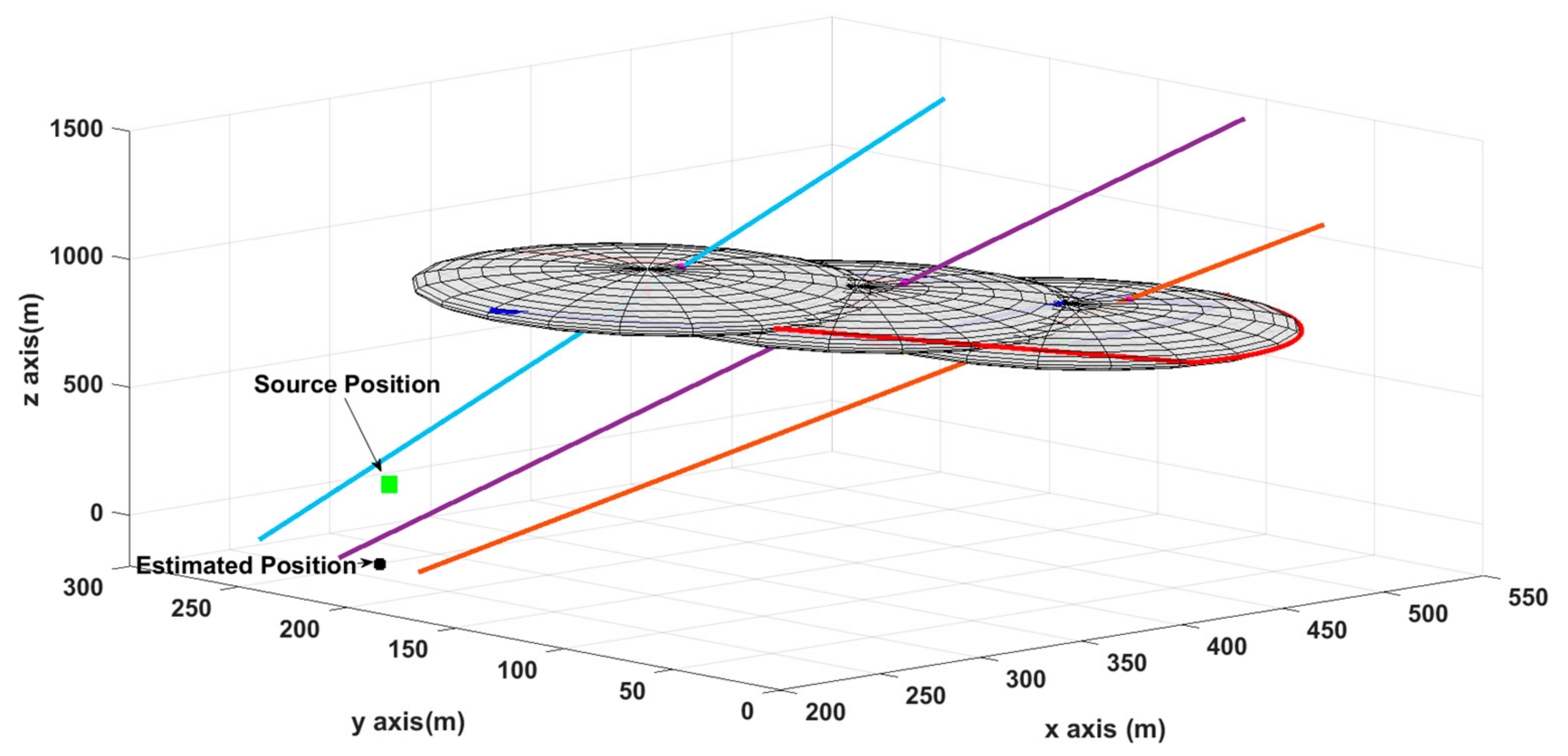
4. Results
5. Conclusions
Funding
Data Availability Statement
Conflicts of Interest
References
- Labib, N.S.; Brust, M.R.; Danoy, G.; Bouvry, P. The Rise of Drones in Internet of Things: A Survey on the Evolution, Prospects and Challenges of Unmanned Aerial Vehicles. IEEE Access 2021, 9, 115466–115487. [Google Scholar] [CrossRef]
- Laoudias, C.; Moreira, A.; Kim, S. A survey of enabling technologies for network localization tracking and navigation. IEEE Commun. Surv. Tutor. 2018, 20, 3607–3644. [Google Scholar] [CrossRef] [Green Version]
- Wang, X.; Roy, S.; Farì, S.; Baldi, S. Adaptive Vector Field Guidance without a Priori Knowledge of Course Dynamics and Wind. IEEE/ASME Trans. Mechatron. 2022, 27, 4597–4607. [Google Scholar] [CrossRef]
- Baldi, S.; Roy, S.; Yang, K.; Liu, D. An Underactuated Control System Design for Adaptive Autopilot of Fixed-Wing Drones. IEEE/ASME Trans. Mechatron. 2022, 27, 4045–4056. [Google Scholar] [CrossRef]
- Wang, X.; Roy, S.; Farì, S.; Baldi, S. The problem of reliable design of vector-field path following in the presence of uncertain course dynamics. IFAC-Pap. OnLine 2020, 53, 9399–9404. [Google Scholar] [CrossRef]
- Nasralla, M.M.; Rehman, I.U.; Sobnath, D.; Paiva, S. Computer Vision and Deep Learning-Enabled UAVs: Proposed Use Cases for Visually Impaired People in a Smart City. In Proceedings of the Computer Analysis of Images and Patterns CAIP 2019, Salerno, Italy, 6 September 2019. Communications in Computer and Information Science Springer. [Google Scholar]
- Koohifar, F.; Guvenc, I.; Sichitiu, M.L. Autonomous Tracking of Intermittent RF Source Using a UAV Swarm. IEEE Access 2018, 6, 15884–15897. [Google Scholar] [CrossRef]
- Bi, F.; Lei, M.; Wang, Y. Context-aware MDNet for target tracking in UAV remote sensing videos. Int. J. Remote Sens. 2020, 41, 3784–3797. [Google Scholar] [CrossRef]
- He, J.; Geng, Y.; Pahlavan, K. Toward accurate human tracking: Modeling time-of-arrival for wireless wearable sensors in multipath environment. IEEE Sens. J. 2014, 14, 3996–4006. [Google Scholar]
- Nguyen, N.H.; Doğançay, K. Instrumental Variable Based Kalman Filter Algorithm for Three-Dimensional AOA Target Tracking. IEEE Signal Process. Lett. 2018, 25, 1605–1609. [Google Scholar] [CrossRef]
- Fletcher, F.; Ristic, B.; Mušicki, D. Recursive estimation of emitter location using TDOA measurements from two UAVs. In Proceedings of the 10th International Conference on Information Fusion, Québec, QC, Canada, 9–12 July 2007. [Google Scholar]
- Lin, A.; Ling, H. Doppler and direction-of-arrival (DDOA) radar for multiple-mover sensing. IEEE Trans. Aerosp. Electron. Syst. 2007, 43, 345–361. [Google Scholar] [CrossRef]
- Guzey, N.; Xu, H.; Jagannathan, S. Localization of Near-Field Radio Controlled Unintended Emitting Sources in the Presence of Multipath Fading. IEEE Trans. Instrum. Meas. 2014, 63, 2696–2703. [Google Scholar] [CrossRef]
- Viani, F.; Lizzi, L.; Rocca, P.; Benedetti, M.; Donelli, M.; Massa, A. Object tracking through RSSI measurements in wireless sensor networks. Electron. Lett. 2008, 44, 653–654. [Google Scholar] [CrossRef] [Green Version]
- Lagias, A.E.; Lagkas, T.D.; Zhang, J. New RSSI-based tracking for following mobile targets using the law of cosines. IEEE Wirel. Commun. Lett. 2017, 7, 392–395. [Google Scholar] [CrossRef]
- Uluskan, S.; Filik, T.A. Geometrical Closed Form Solution for RSS Based Far-Field Localization: Direction of Exponent Uncertainty. Wirel. Netw. 2019, 25, 215–227. [Google Scholar] [CrossRef]
- Zengin, U.; Dogan, A. Real-Time Target Tracking for Autonomous UAVs in Adversarial Environments: A Gradient Search Algorithm. IEEE Trans. Robot. 2007, 23, 294–307. [Google Scholar] [CrossRef]
- Haoran, S.; Faxing, L.; Hangyu, W.; Junfei, X. Optimal observation configuration of UAVs based on angle and range measurements and cooperative target tracking in three-dimensional space. J. Syst. Eng. Electron. 2020, 31, 996–1008. [Google Scholar] [CrossRef]
- Zhou, M.; Lin, J.; Liang, S.; Du, W.; Cheng, L. A UAV patrol system based on Bluetooth localization. In Proceedings of the 2nd Asia-Pacific Conference on Intelligent Robot Systems (ACIRS), Wuhan, China, 16–18 June 2017; pp. 205–209. [Google Scholar]
- Zhang, W.; Song, K.; Rong, X.; Li, Y. Coarse-to-Fine UAV Target Tracking with Deep Reinforcement Learning. IEEE Trans. Autom. Sci. Eng. 2019, 16, 1522–1530. [Google Scholar] [CrossRef]
- Hasanzade, M.; Herekoğlu, Ö.; Yeniçeri, R.; Koyuncu, E.; İnalhan, G. RF Source Localization using Unmanned Aerial Vehicle with Particle Filter. In Proceedings of the 9th International Conference on Mechanical and Aerospace Engineering (ICMAE), Budapest, Hungary, 10–13 July 2018. [Google Scholar]
- Hasanzade, M.; Herekoglu, O.; Ure, N.K.; Koyuncu, E.; Yeniceri, R.; Inalhan, G. Localization and tracking of RF emitting targets with multiple unmanned aerial vehicles in large scale environments with uncertain transmitter power. In Proceedings of the International Conference on Unmanned Aircraft Systems (ICUAS), Miami, FL, USA, 13–16 June 2017. [Google Scholar]
- Spyridis, Y.; Lagkas, T.; Sarigiannidis, P.; Zhang, J. Modelling and simulation of a new cooperative algorithm for UAV swarm coordination in mobile RF target tracking. Simul. Model. Pract. Theory 2021, 107, 102232. [Google Scholar] [CrossRef]
- Liang, J.; Liang, Q. RF Emitter Location Using a Network of Small Unmanned Aerial Vehicles (SUAVs). In Proceedings of the IEEE International Conference on Communications (ICC), Kyoto, Japan, 8–9 June 2011. [Google Scholar]
- Charrow, B.; Michael, N.; Kumar, V. Cooperative multi-robot estimation and control for radio source localization. Int. J. Robot. Res. (IJRR) 2014, 33, 569–580. [Google Scholar] [CrossRef]
- Dehghan, S.M.; Moradi, H.; Shahidian, S.A. Optimal path planning for DRSSI based localization of an RF source by multiple UAVs. In Proceedings of the 2014 Second RSI/ISM International Conference on Robotics and Mechatronics (ICRoM), Tehran, Iran, 15–17 October 2014; pp. 558–563. [Google Scholar]
- Güzey, H.M.; Güzey, N. Adaptive hybrid formation-search and track controller of UAVs. Int. J. Syst. Sci. 2022, 53, 2301–2317. [Google Scholar] [CrossRef]
- Lee, J.H.; Buehrer, R.M. Fundamentals of received signal strength-based position location. In Handbook of Position Location: Theory, Practice, and Advances; Zekavat, R., Buehrer, R.M., Eds.; Wiley: Singapore, 2012; pp. 359–394. [Google Scholar]
- Chan, Y.T.; Lee, B.H.; Inkol, R.J.; Chan, F. Estimation of emitter power, location, and path loss exponent. In Proceedings of the CCECE Montreal, Quebec, Canada, 29 April–2 May 2012. [Google Scholar]


| Study | Method | Advantages | Limitation/Disadvantages |
|---|---|---|---|
| S. M. Denghan et al. [26] | Differential RSSI | Transmit power value is not required | Nonlinear modeling for FIM and EKF |
| Hasanzade et al. [22] | RSSI with EKF | Noise reduction with EKF | Transmit power value required, it is estimated with NN |
| Hasanzade et al. [22] | RSSI with Particle Filter | Only one UAV is requied | High computational complexity of Partical Filter |
| Zhou et al. [19] | Both RSSI and Visual localiation | Localization with Bluetooth | Images can be poor for some circumtances |
| Standard Deviation Ratio | Mean Error |
|---|---|
| 2% | 28.3 m |
| 4% | 52.66 m |
| 8% | 145.7 m |
Publisher’s Note: MDPI stays neutral with regard to jurisdictional claims in published maps and institutional affiliations. |
© 2022 by the author. Licensee MDPI, Basel, Switzerland. This article is an open access article distributed under the terms and conditions of the Creative Commons Attribution (CC BY) license (https://creativecommons.org/licenses/by/4.0/).
Share and Cite
Güzey, N. RF Source Localization Using Multiple UAVs through a Novel Geometrical RSSI Approach. Drones 2022, 6, 417. https://doi.org/10.3390/drones6120417
Güzey N. RF Source Localization Using Multiple UAVs through a Novel Geometrical RSSI Approach. Drones. 2022; 6(12):417. https://doi.org/10.3390/drones6120417
Chicago/Turabian StyleGüzey, Nurbanu. 2022. "RF Source Localization Using Multiple UAVs through a Novel Geometrical RSSI Approach" Drones 6, no. 12: 417. https://doi.org/10.3390/drones6120417
APA StyleGüzey, N. (2022). RF Source Localization Using Multiple UAVs through a Novel Geometrical RSSI Approach. Drones, 6(12), 417. https://doi.org/10.3390/drones6120417