Article

RF Source Localization Using Multiple UAVs through a Novel Geometrical RSSI Approach

Department of Electrical-Electronics Engineering, Sivas University of Science and Technology, Sivas 58000, Turkey
Drones 2022, 6(12), 417; https://doi.org/10.3390/drones6120417
Submission received: 9 November 2022 / Revised: 8 December 2022 / Accepted: 12 December 2022 / Published: 15 December 2022

Abstract

:
In this paper, a novel geometrical localization scheme based on the Received Signal Strength Indicator (RSSI) is developed for a group of unmanned aerial vehicles (UAVs). Since RSSI-based localization does not require complicated hardware, it is the correct choice for RF target localization. In this promising work, unlike the other techniques given in the literature, transmit power or path loss exponent information is not needed. The procedure depends on the received power difference of each receiver in UAVs. In the developed scheme, four UAVs forming two groups fly in perpendicular planes. Each UAV in the group moves in a circle, keeping its distance from the plane’s center until it gets equal power with the other members of its group. Using this movement rate, lines passing through the source position are calculated. The intersection of these lines gives the position of the RF target. However, in a noisy environment, the lines do not intersect at one point. Therefore, the algorithm given in the manuscript finds a point that has a minimum distance to all lines and is also developed. Simulation results are provided at the end of the manuscript to verify our theoretical claims.

1. Introduction

Unmanned Aerial Vehicles (UAVs) and other new smartly linked platforms have become increasingly integrated into the Internet of Things, which is a vast global network (IoT). UAVs not only provide a practical solution to the drawbacks of fixed terrestrial IoT infrastructure, but also new ways to supply value-added IoT services through a variety of applications ranging from monitoring and surveillance to on-demand last-mile deliveries and people transport. UAVs are predicted to soon be a vital component of our cities and rule the common low-altitude airspace if they live up to their potential [1].
Localization and tracking are crucial issues to be solved in commercial and military applications such as air traffic control, remote sensing, and intelligence, surveillance, and reconnaissance (ISR) [2]. Initially, ground-based methods were used to conduct localization. However, due to the fast development of UAVs and sensor technology, UAVs are now able to be used as airborne sensing devices. Furthermore, some applications, such as search and rescue missions, may require only aerial localization. The aerial vehicles’ mobility and extensive eyesight allow for successful and fast localization. Furthermore, flying above ground level decreases signal propagation uncertainty due to obstacles and enhances RF target identification. However, when the UAV wanted to follow a trajectory to track a target, a control methodology was required. In [3], a vector-field method is proposed that does not require knowledge of course dynamics or wind. In [4,5], an autopilot control system is proposed.
Apart from search, rescue, and surveillance operations, UAVs are also used in smart city applications where high technologies such as IoT and deep learning are used. In [6], it is recommended to use computer vision and deep learning techniques in UAVs to improve the quality of life of visually impaired individuals. UAVs are also used to detect, locate, and track unauthorized UAVs, which have been identified as of the utmost priority both in military and civilian settings. In [7], an intermittent RF source is tracked with a UAV swarm.

2. Related Work

The localization of an RF target by using UAVs is studied in the literature in a number of different ways. Some of the existing approaches include visual characteristics [8], RF time of arrival [9], angle of arrival [10], time difference of arrival [11], Doppler and direction of arrival [12,13], and received signal strength indicator (RSSI) [14,15,16]. Additionally, there are techniques that directly track the target using GPS or range and angle sensors [17,18]. In [19], Bluetooth is used instead of GPS, and localization is enhanced with an intelligent camera module.
Visual feature-based algorithms are effective in locating an item in a variety of situations; however, they may suffer in long-range localization operations, particularly when vision is obscured, or light conditions are poor [20]. Thermal cameras can help with this problem, but when the weather is hot, they can produce a lot of false positives. Time of arrival and angle of arrival techniques require more complicated antennas and synchronization challenges that might arise owing to the mobility of UAVs. Thus, in some circumstances, the hardware configuration for determining the signal’s direction may not be accessible, and the UAVs may be forced to depend only on the signal strength to locate the target. Furthermore, because of the importance of energy restrictions in UAVs, a simpler method is typically used to ensure that flight duration is increased, and the mission is accomplished within the time constraints. RSSI techniques may yield promising outcomes in this scenario.
Because of this, RSSI-based localization and tracking have been studied in the literature. For example, [16] introduces an RSSI tracking method that makes use of the law of cosines along with estimated distances from the RF source to determine the steering angle that points the tracking agent toward the target. However, they presuppose a fixed transmit power that cannot always be met. A particle filter approach [21] and RSSI-based method are presented in [22], where the transmit power is estimated with an artificial neural network before the localization process, which makes the procedure more complicated.
Particularly, UAVs flying in a predefined formation can locate and follow a target of interest in order to gather information or deliver critical services [23]. In [24], it outlines a set of UAVs with RSSI sensors that conduct trilateration, with the target’s position established by a fusion center and the distances from the RF source approximated using the log-normal shadowing model. For the localization of stationary RF targets in non-convex settings, estimation and control techniques for a team of robots were presented in [25]. In [26], differential RSSI (DRSSI) model is used for localization. The difference in received signal powers by the UAVs is used to calculate the heading angles of the UAVs. Furthermore, DRSSI measurements are enhanced with an Extended Kalman Filter for more accurate results.
In our previous study, UAV groups used the signal strength difference received by the UAVs for target localization. The UAV group was positioned above the target on the x and y axes by preserving the formation. Since the position of the formation center is known, the position of the target is determined [27]. Table 1 gives a summary of selected localization methods.
This study examines a swarm of cooperative UAVs that are outfitted with basic RSSI sensors and coordinate their movements to localize an object that emits radio waves. The system is based on comparing the signal strengths received by the antennas carried by four UAVs, which are divided into two groups. Each group consists of two UAVs. In each group, UAVs move in a circular manner in the plane they fly to receive equal signal power with their group mate. The UAV that is closer to the source moves away from the source, and the UAV that is far from the source approaches the source at the same rate, and they acquire equal power. By using the moving rate for each group, the location of the RF source is calculated geometrically. Further, no time synchronization of transmitter and receiver antennas is required in this approach. Two circles are designed, one in the x-y plane and the other in the x-z plane, which are perpendicular to each other, and their centers are fixed. The desired trajectories of the UAVs are calculated in real-time so that they remain on these circles. The movements of the UAVs on the circle are calculated according to the difference in the signal strength they receive. With the PID logic, the UAVs are moved so that the difference in the received signal power will be zero. In the developed algorithm, a total of four UAVs were used, two in the x-y plane and two in the x-z plane. These are the minimum numbers for the algorithm to work. Target localization accuracy can be increased by using more UAVs. In addition, using more than four UAVs will increase the cost in practice.
The research objective in this study is:
  • Ability to do localization in GPS-denied environments.
  • Ability to do localization without knowing the output power of the target and without the need for time synchronization between the transceiver and receiver antennas
The contribution of this article can be summarized as follows:
  • For environments with weak GPS signals, a novel geometry-based localization method has been developed.
  • Since the receiving antennas are on the UAVs, a method has been developed that will make it possible to detect the target location more precisely by increasing the distances between the UAVs.
  • An augmented point on the sphere is calculated where the line passing through this point and sphere center also passes through the target position.
The rest of the paper is organized as follows: in Section 3, background on RSSI and methodology of the proposed method are given, simulation results to verify the given method are mentioned in Section 4, and the conclusion of this study and future work are offered in Section 5.

3. Materials and Method

The details of RSSI-based localization using UAVs are given in this section. RSSI is the technique that calculates the power of the signal strength at the receiver as a function of different parameters, such as transmitting power, characteristics of the receiver and transmitter antennas, distance between the receiver and transmitter, etc. [28]. Measured signal strength can be converted to the distance between the transmitter and the receiver. In space, as the distance between the transmitter and receiver changes, the signal strength also changes. This can be measured by using the following Friis equation [28]:
P r = P t D r D t λ 4 π d γ + N ( 0 , σ )
where P t is the transmitted signal power from the transmitter, d is the distance between the emitter and receiver, γ is the path loss exponent, and λ is the wavelength of the transmitted signal. An additive Gaussian noise N is included within the equation to model error caused by reflections, measurements, and so on. The path loss exponent γ can take a value between the range 2 and 4 due to different environmental conditions. It can also exceed this bound under some special conditions [29].
In this manuscript, an RSSI-based geometrical solution is proposed to the localization problem of RF devices in a GPS-denied environment.
The algorithm is derived in the presence of two major challenges:
  • There is no prior information on the target’s location.
  • Signal strength is all that is measured by UAVs; there is no time stamp or other useful information in the signal. There is no direction-finding hardware on board.
To solve the problem, the following two conditions are assumed:
  • There is always a clear line of sight between the UAVs and the target.
  • There are no communication limitations; UAVs may send and receive data without losing information.
The details of the method are given in the following subsections. In the first subsection, the desired posture (3D Cartesian location) of each UAV is calculated so that the UAVs would move on two perpendicular circles. One of the circles is in the x-y plane and at a distance r from the center, and the other is chosen in the x-z plane and at a distance r from the center. In the second subsection, rotating angles are calculated that will allow the UAVs to rotate on the circle while maintaining the 2r distance between them. The derivatives of the rotating angles are calculated using the difference in received signal powers.

3.1. Desired Initial Posture Derivation of Four UAVs

Suppose there are four UAVs equipped with RSSI receivers in arbitrary initial locations. Their initial desired locations are derived as follows:
x 1 d t 0 = x c r cos ( α t 0 ) y 1 d t 0 = y c r sin ( α t 0 ) z 1 d = z c x 3 d t 0 = x c + r cos ( α t 0 ) y 3 d t 0 = y c + r sin ( α t 0 ) z 3 d = z c x 2 d t 0 = x c r sin ( β t 0 ) y 2 d = y c z 3 d t 0 = z c r cos ( β t 0 ) x 4 d t 0 = x c + r cos ( β t 0 ) y 4 d = y c z 4 d t 0 = z c + r sin ( β t 0 )
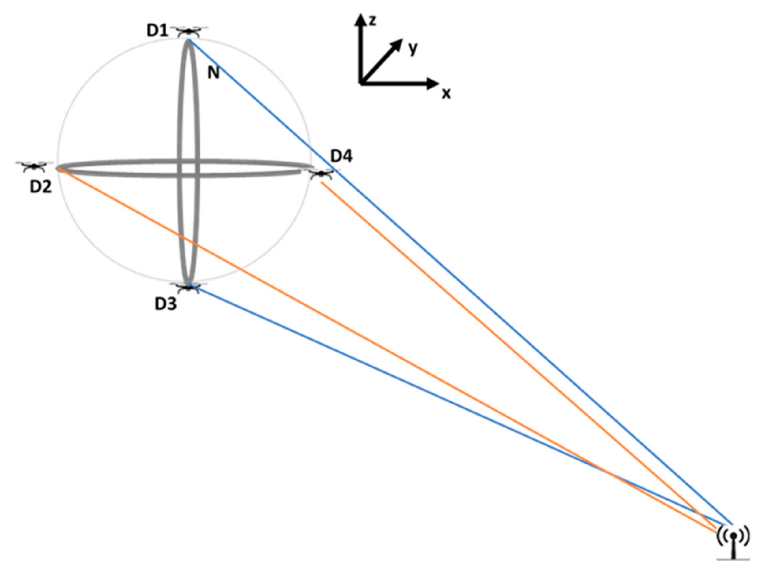
where C ( x c , y c , z c ) is the center of the formation, r is the radius of the circles, α t 0 and β t 0 are the initial rotation angles, given as in Figure 1, defined by the user, and t 0 is the initial time. D1 and D3 UAVs form a group in the x-y plane, while D2 and D4 UAVs form another group in the x-z plane.
The desired initial postures (2) of the UAVs moving both in the x-y axis and in the x-z axis are calculated in a way that satisfies two basic constraints: (i) Both UAVs are at a distance of r from the center; (ii) the distance between two UAVs is 2r. Thus, UAVs move on the predetermined circle, and the distance between the UAVs is fixed. Derivation of the rotating angle dynamics is given in the next subsection.

3.2. Rotating Angle Calculation

To find the direction of the target in both vertical and horizontal planes, the signal power differences are defined as follows:
e 1 = P 3 P 1 e 2 = P 4 P 2
where P 1 , , P 4 are the received signal powers by D 1 , , D 4 , respectively, while e 1 is obtained from the difference in signal strengths of the 3rd UAV and the 1st UAV, e 2 is obtained from the power differences of the 4th UAV and the 2nd UAV. Then the error dynamics are given as follows:
e ˙ 1 = P ˙ 3 P ˙ 1 e ˙ 2 = P ˙ 4 P ˙ 2
Two UAVs moving in the x-z axis are used to find the horizontal direction of the target, whereas UAVs moving in the x-y plane are used to find the vertical direction of the target. Derivation of α and β are calculated to make the difference of the signal strength received by the two UAVs zero. PID controller logic is used, and derivative of α was defined as the function of e 1 and derivative β as the function of e 2 . The desired rotating angle dynamics are defined as:
α ˙ = k P e 1 + k I t 0 t e 1 ( τ ) d τ + k D e ˙ 1 β ˙ = k P e 2 + k I t 0 t e 2 ( τ ) d τ + k D e ˙ 2
where k P > 0 , k I > 0 , and k D > 0 are design parameters. Then the current rotating angles are found as:
α t = α t 0 + t 0 t α ˙ ( τ ) d τ β t = β t 0 + t 0 t β ˙ ( τ ) d τ
Changing the α and β in time (6) will automatically change the desired locations of the UAVs according to (7). This change continues until e 1 and e 2 converges to zero or a pre-defined and tolerable error bound.
x 1 d t = x c r cos ( α t ) y 1 d t = y c r sin ( α t ) z 1 d = z c x 3 d t = x c + r cos ( α t ) y 3 d t = y c + r sin ( α t ) z 3 d = z c x 2 d t = x c r sin ( β t ) y 2 d = y c z 3 d t = z c r cos ( β t ) x 4 d t = x c + r cos ( β t ) y 4 d = y c z 4 d t = z c + r sin ( β t )
Remark: 
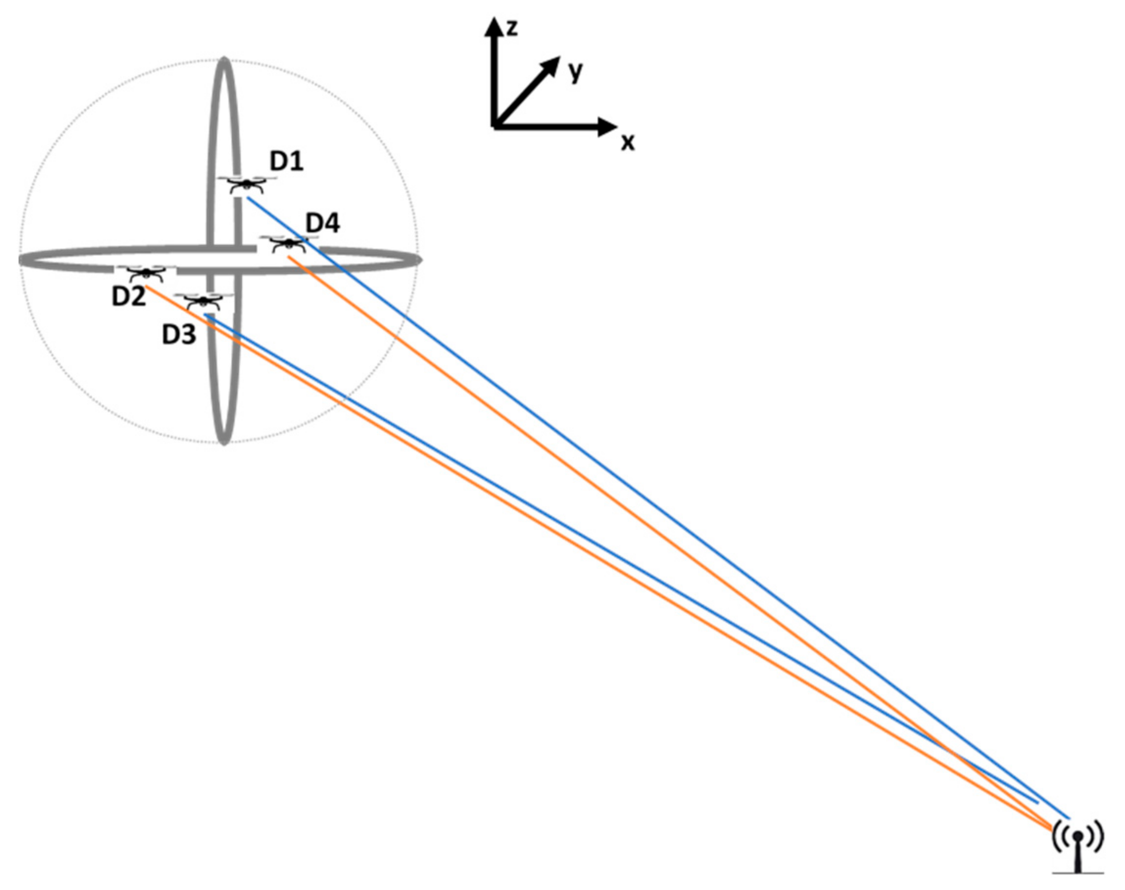
Consider the scenario shown in Figure 2, they detect a target while flying. The received signal power in each group is compared by itself, and UAVs move in their planes until they receive equal signal power. In this scenario, D4 gets more power than D2, so D4 moves away from the target and D2 moves towards the target. Same as for D1 and D3, D1 receives less power than D3, therefore D1 approaches to the target while D3 moves away from the target, as given in Figure 3.
Next, the augmented point and the lines that pass through the target position are calculated.

3.3. Augmented Point and Direction Calculation

When power errors are within a tolerable error range, the plane formed by the line through the D1–D3 and the line through the D2–D4 is calculated. The line that will be perpendicular to this plane and pass through the center is determined. As the first step in calculating the line, an augmented point is calculated on the sphere formed by the perpendicular circles.
An augmented point, A ( x a u g , y a u g , z a u g ) , is defined on the sphere, which has equal distance to each UAV and satisfies the criteria below:
( x a x c ) 2 + ( y a y c ) 2 + ( z a z c ) 2 = r d a 1 = ( x a x 1 d ) 2 + ( y a y 1 d ) 2 + ( z a z 1 d ) 2 d a 2 = ( x a x 2 d ) 2 + ( y a y 2 d ) 2 + ( z a z 2 d ) 2 d a 3 = ( x a x 3 d ) 2 + ( y a y 3 d ) 2 + ( z a z 3 d ) 2 d a 4 = ( x a x 4 d ) 2 + ( y a y 4 d ) 2 + ( z a z 4 d ) 2 d a 1 = d a 2 = d a 3 = d a 4
with these criteria (8), the augmented point is calculated as follows:
r a = r cos ( β ) z a u g = z c + r sin ( α ) sin ( β ) x a u g = x c r a sin ( α ) y a u g = y c r a c o s ( α )
Claim: The line passes through the sphere’s center C ( x c , y c , z c ) and the augmented point A ( x a u g , y a u g , z a u g ) also intersects the target position. The definition of the line passing through the A ( x a u g , y a u g , z a u g ) and C ( x c , y c , z c ) is derived as follows:
y = x x a u g x c x a u g y c y a u g + y a u g z = y y a u g y c y a u g z c z a u g + z a u g
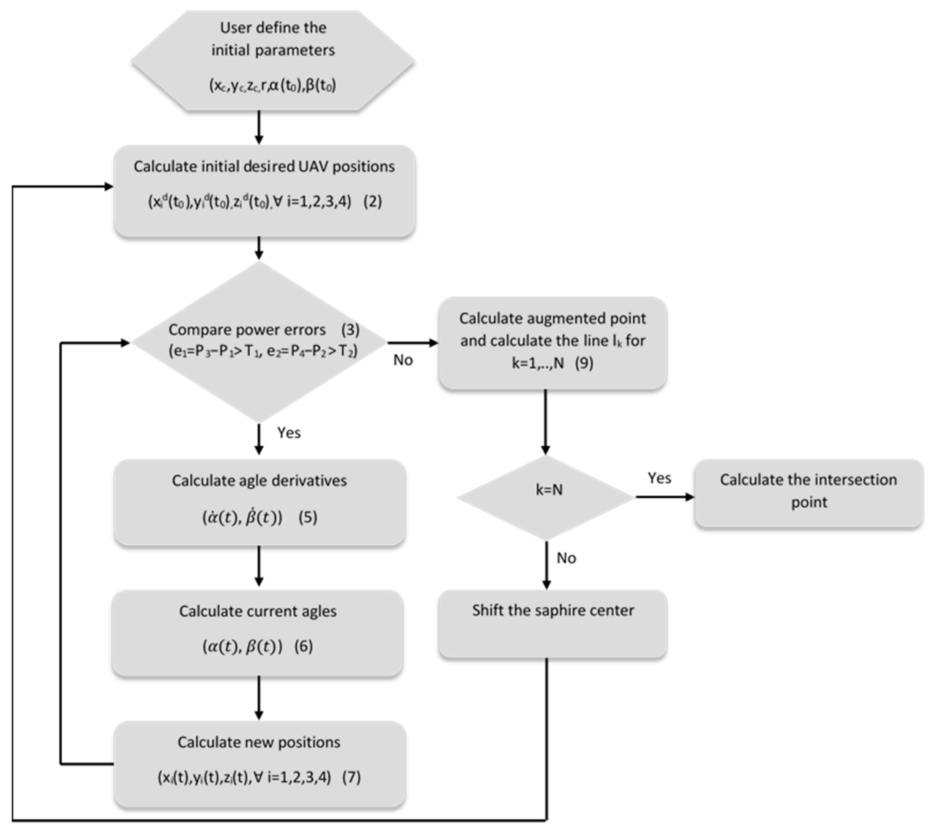
This line is in the direction of the source. For the sake of localization, the group of UAVs is moved while keeping the consensus to receive equal signal power. In their new location, a new line is generated with new angles. This procedure is conducted multiple times. Since all the lines are directed through the source, their intersection will give the location of the source. In a noise-free environment, two lines are enough to locate the target. However, since signal power may be seriously influenced by the environment and may have a high level of noise, the lines may not intersect at one point. In a noisy environment, the lines may not go through the source. Therefore, the point that has the shortest distance to all lines is assigned as the source location. The Algorithm 1 that gives the minimum distance to all lines is given in below. The overall framework of the proposed localization process is given in the flowchart given in Figure 4.
Algorithm 1: Minimum distance to lines calculation ( x e s t _ f , y e s t _ f , z e s t _ f ).
1: Set n = length of line segments, N = number of line segments; P is a very large constant
2:  p = 1 ;
3: for k = 1   t o   N ;
4:  for m = 1   t o   N
5:     if m k
6:    d min = P
7:   for i = 1   t o   n
8:     for j = 1   t o   n
9:        d = x ( k , i ) x ( m , j ) 2 + y ( k , i ) y ( m , j ) 2 + z ( k , i ) z ( m , j ) 2
10:        if d < d m i n
11:          d m i n = d , i m i n = i , j m i n = j ,
12:       end if
13:     end for
14:   end for
15:   x e s t ( p ) = x ( k , i min ) + x ( m , j min ) 2 , y e s t ( p ) = y ( k , i min ) + y ( m , j min ) 2 , z e s t ( p ) = z ( k , i min ) + z ( m , j min ) 2
16:      p = p + 1
17:     end for
18:   end for
19: end for

4. Results

In this section, the performance of the proposed method is given. Localization of a target in a 1 × 1 km2 search area was considered for simulation studies. The target is assumed to be on the ground. In the beginning, UAVs search the GPS-denied area until they receive an RF signal. Then they rotate on the given circles until the UAVs in each group receive equal power.
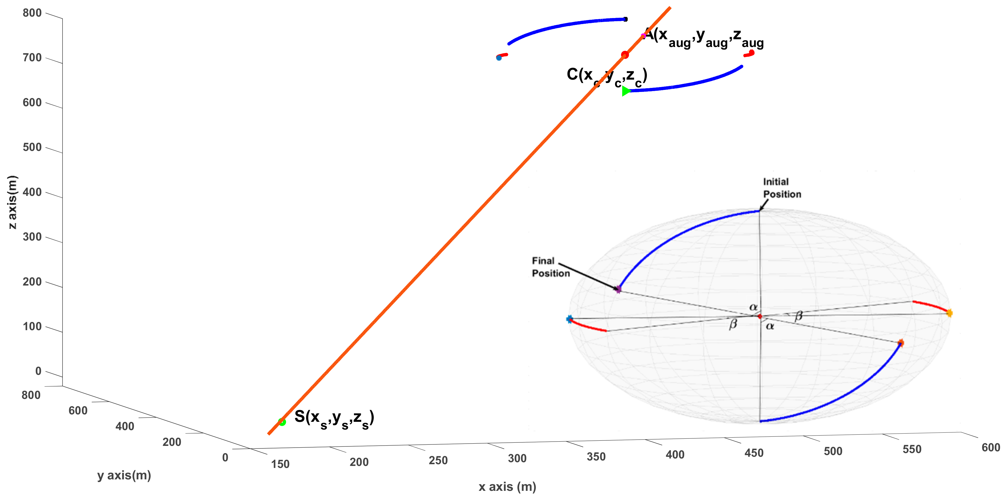
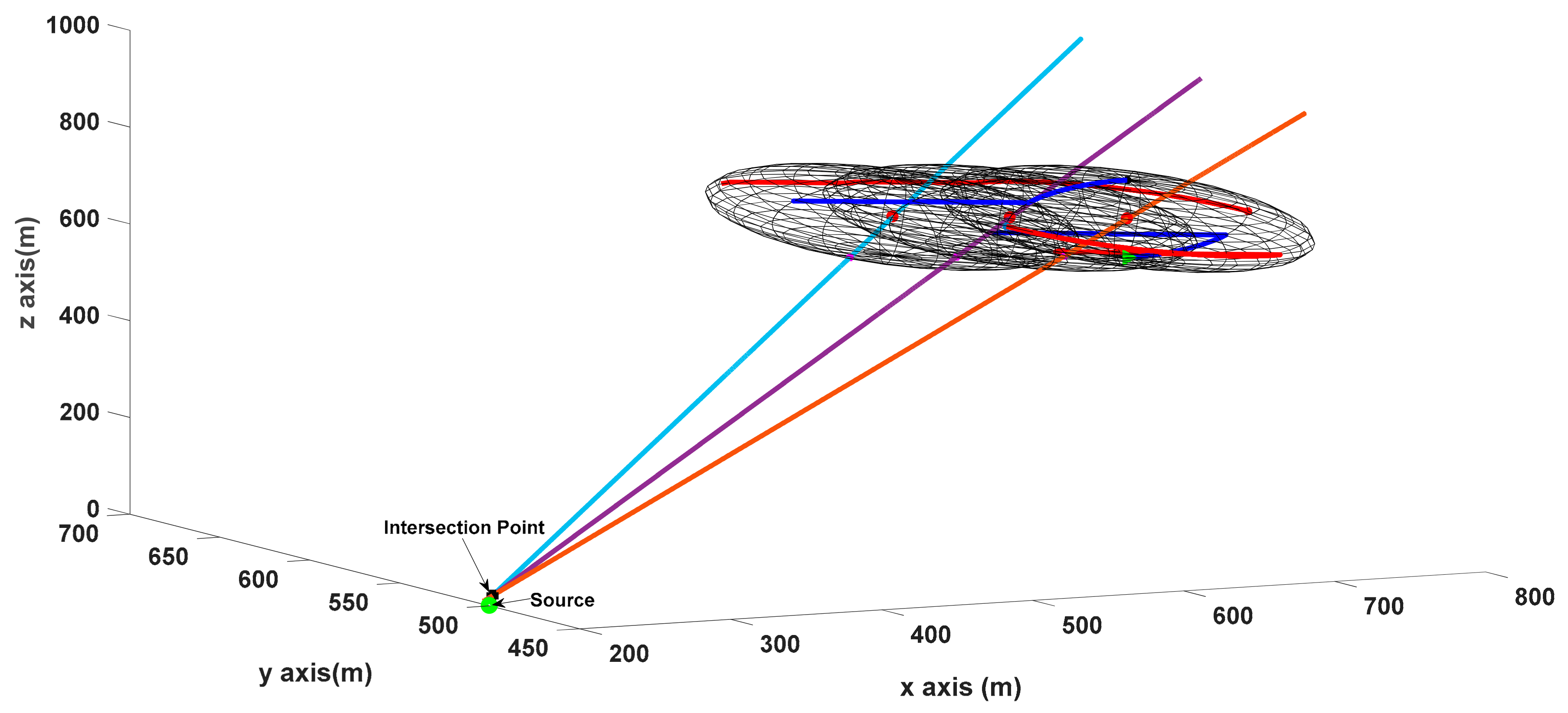
As mentioned above, the line intersects the augmented point, and the formation center will also intersect the source position as given in Figure 5. Movements of UAVs on the sphere and the angles are also demonstrated in Figure 5. One line is not enough to find the source’s location. By moving the UAV group and keeping the formation, multiple lines are generated, as demonstrated in Figure 6. The intersection of these lines gives the source’s location.
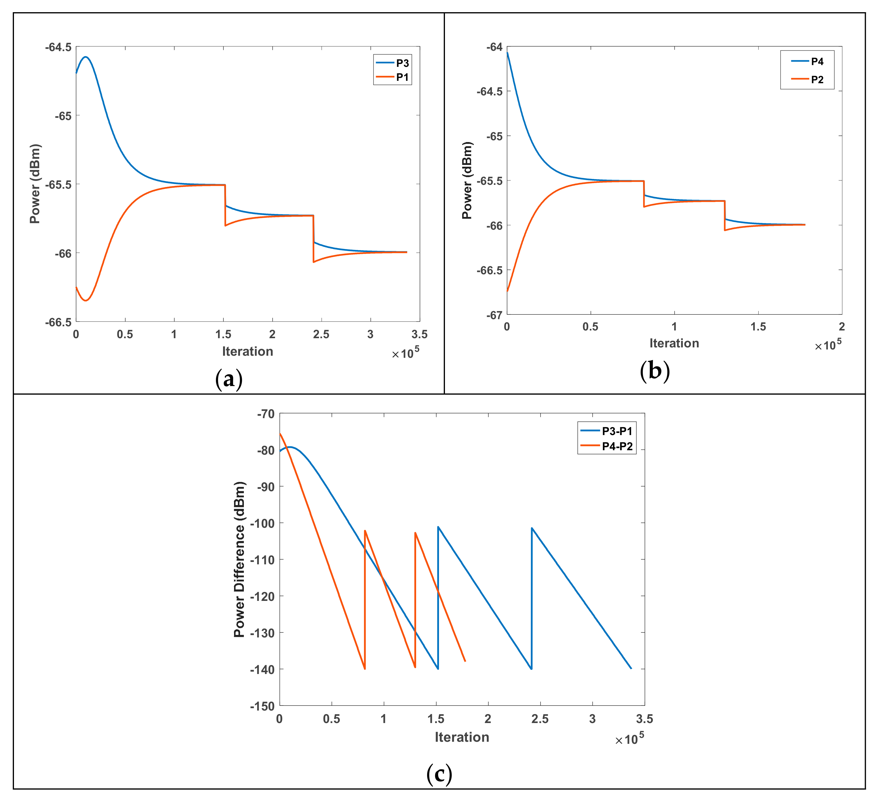
As shown in Figure 6, UAVs with different received signal powers initially act in a way to equalize the received power. When the center of gravity moves, the procedure starts again and the received signal powers are equalized again. New augmented points with new angle values are calculated, and the location of the target is determined by the intersection lines passing through the center and the augmented points. Figure 7 demonstrates the received power difference of the UAVs in each group.
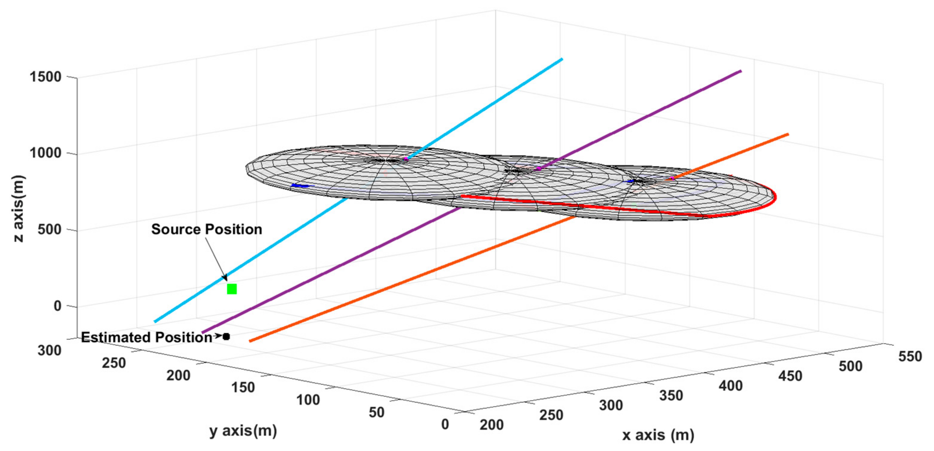
However, due to the noise effects, the received signal power values may vary from their originals. Although the mean of multiple RSSI values is used in the algorithm, the lines may not intersect at one point. In this situation, in order to find the point that has a shortest distance to all lines the algorithm given in previous section is utilized. The point that has a minimum distance to all lines is referred to as the source location, and the result is demonstrated in Figure 8.
Figure 8 shows target detection when the received signal strength is different from the theoretically calculated signal power (1). Scanning is performed when the sphere center is at three different points. After 100 Monte Carlo simulations, the mean error value is found to be 52.66 m when a noise with a 4% standard deviation over the signal power is added. Table 2 shows localization errors for different noise values.
As can be seen from the table, localization error increases when the noise level increases. As a continuation of this study, it is aimed to reduce the noise level by using nonlinear filters. Thus, the proposed localization method will provide more accurate results.

5. Conclusions

A novel localization method that can work in GPS-denied environments which can occur due to tall buildings, trees, canyon walls blocking the GPS satellite signals, or a lack of coverage was proposed. This powerful geometrical solution performs the localization process without the need for transmit power and path loss exponent information. The procedure depends on the difference in received signal power measured by RSSI sensors. UAVs move until each UAV receives equal power while keeping the formation. With this movement rate, lines intersecting at the source location are calculated. In a noise-free environment, two lines are enough to calculate the position. However, in a noisy environment, these lines do not intersect. Therefore, generating more lines will improve localization performance. An algorithm that finds a point which has a minimum distance to all lines is also given in this manuscript.
In this study, the source location is calculated as the point that has a minimum distance to all lines. Nonlinear filtering methods will be considered to find the source location with minimum error will be considered as a future study. Furthermore, results are given based on computer simulations. With the real-time application of the algorithm, the performance of the method will be examined more precisely.

Funding

This research received no external funding.

Data Availability Statement

Not applicable.

Conflicts of Interest

The author declares no conflict of interest.

References

  1. Labib, N.S.; Brust, M.R.; Danoy, G.; Bouvry, P. The Rise of Drones in Internet of Things: A Survey on the Evolution, Prospects and Challenges of Unmanned Aerial Vehicles. IEEE Access 2021, 9, 115466–115487. [Google Scholar] [CrossRef]
  2. Laoudias, C.; Moreira, A.; Kim, S. A survey of enabling technologies for network localization tracking and navigation. IEEE Commun. Surv. Tutor. 2018, 20, 3607–3644. [Google Scholar] [CrossRef] [Green Version]
  3. Wang, X.; Roy, S.; Farì, S.; Baldi, S. Adaptive Vector Field Guidance without a Priori Knowledge of Course Dynamics and Wind. IEEE/ASME Trans. Mechatron. 2022, 27, 4597–4607. [Google Scholar] [CrossRef]
  4. Baldi, S.; Roy, S.; Yang, K.; Liu, D. An Underactuated Control System Design for Adaptive Autopilot of Fixed-Wing Drones. IEEE/ASME Trans. Mechatron. 2022, 27, 4045–4056. [Google Scholar] [CrossRef]
  5. Wang, X.; Roy, S.; Farì, S.; Baldi, S. The problem of reliable design of vector-field path following in the presence of uncertain course dynamics. IFAC-Pap. OnLine 2020, 53, 9399–9404. [Google Scholar] [CrossRef]
  6. Nasralla, M.M.; Rehman, I.U.; Sobnath, D.; Paiva, S. Computer Vision and Deep Learning-Enabled UAVs: Proposed Use Cases for Visually Impaired People in a Smart City. In Proceedings of the Computer Analysis of Images and Patterns CAIP 2019, Salerno, Italy, 6 September 2019. Communications in Computer and Information Science Springer. [Google Scholar]
  7. Koohifar, F.; Guvenc, I.; Sichitiu, M.L. Autonomous Tracking of Intermittent RF Source Using a UAV Swarm. IEEE Access 2018, 6, 15884–15897. [Google Scholar] [CrossRef]
  8. Bi, F.; Lei, M.; Wang, Y. Context-aware MDNet for target tracking in UAV remote sensing videos. Int. J. Remote Sens. 2020, 41, 3784–3797. [Google Scholar] [CrossRef]
  9. He, J.; Geng, Y.; Pahlavan, K. Toward accurate human tracking: Modeling time-of-arrival for wireless wearable sensors in multipath environment. IEEE Sens. J. 2014, 14, 3996–4006. [Google Scholar]
  10. Nguyen, N.H.; Doğançay, K. Instrumental Variable Based Kalman Filter Algorithm for Three-Dimensional AOA Target Tracking. IEEE Signal Process. Lett. 2018, 25, 1605–1609. [Google Scholar] [CrossRef]
  11. Fletcher, F.; Ristic, B.; Mušicki, D. Recursive estimation of emitter location using TDOA measurements from two UAVs. In Proceedings of the 10th International Conference on Information Fusion, Québec, QC, Canada, 9–12 July 2007. [Google Scholar]
  12. Lin, A.; Ling, H. Doppler and direction-of-arrival (DDOA) radar for multiple-mover sensing. IEEE Trans. Aerosp. Electron. Syst. 2007, 43, 345–361. [Google Scholar] [CrossRef]
  13. Guzey, N.; Xu, H.; Jagannathan, S. Localization of Near-Field Radio Controlled Unintended Emitting Sources in the Presence of Multipath Fading. IEEE Trans. Instrum. Meas. 2014, 63, 2696–2703. [Google Scholar] [CrossRef]
  14. Viani, F.; Lizzi, L.; Rocca, P.; Benedetti, M.; Donelli, M.; Massa, A. Object tracking through RSSI measurements in wireless sensor networks. Electron. Lett. 2008, 44, 653–654. [Google Scholar] [CrossRef] [Green Version]
  15. Lagias, A.E.; Lagkas, T.D.; Zhang, J. New RSSI-based tracking for following mobile targets using the law of cosines. IEEE Wirel. Commun. Lett. 2017, 7, 392–395. [Google Scholar] [CrossRef]
  16. Uluskan, S.; Filik, T.A. Geometrical Closed Form Solution for RSS Based Far-Field Localization: Direction of Exponent Uncertainty. Wirel. Netw. 2019, 25, 215–227. [Google Scholar] [CrossRef]
  17. Zengin, U.; Dogan, A. Real-Time Target Tracking for Autonomous UAVs in Adversarial Environments: A Gradient Search Algorithm. IEEE Trans. Robot. 2007, 23, 294–307. [Google Scholar] [CrossRef]
  18. Haoran, S.; Faxing, L.; Hangyu, W.; Junfei, X. Optimal observation configuration of UAVs based on angle and range measurements and cooperative target tracking in three-dimensional space. J. Syst. Eng. Electron. 2020, 31, 996–1008. [Google Scholar] [CrossRef]
  19. Zhou, M.; Lin, J.; Liang, S.; Du, W.; Cheng, L. A UAV patrol system based on Bluetooth localization. In Proceedings of the 2nd Asia-Pacific Conference on Intelligent Robot Systems (ACIRS), Wuhan, China, 16–18 June 2017; pp. 205–209. [Google Scholar]
  20. Zhang, W.; Song, K.; Rong, X.; Li, Y. Coarse-to-Fine UAV Target Tracking with Deep Reinforcement Learning. IEEE Trans. Autom. Sci. Eng. 2019, 16, 1522–1530. [Google Scholar] [CrossRef]
  21. Hasanzade, M.; Herekoğlu, Ö.; Yeniçeri, R.; Koyuncu, E.; İnalhan, G. RF Source Localization using Unmanned Aerial Vehicle with Particle Filter. In Proceedings of the 9th International Conference on Mechanical and Aerospace Engineering (ICMAE), Budapest, Hungary, 10–13 July 2018. [Google Scholar]
  22. Hasanzade, M.; Herekoglu, O.; Ure, N.K.; Koyuncu, E.; Yeniceri, R.; Inalhan, G. Localization and tracking of RF emitting targets with multiple unmanned aerial vehicles in large scale environments with uncertain transmitter power. In Proceedings of the International Conference on Unmanned Aircraft Systems (ICUAS), Miami, FL, USA, 13–16 June 2017. [Google Scholar]
  23. Spyridis, Y.; Lagkas, T.; Sarigiannidis, P.; Zhang, J. Modelling and simulation of a new cooperative algorithm for UAV swarm coordination in mobile RF target tracking. Simul. Model. Pract. Theory 2021, 107, 102232. [Google Scholar] [CrossRef]
  24. Liang, J.; Liang, Q. RF Emitter Location Using a Network of Small Unmanned Aerial Vehicles (SUAVs). In Proceedings of the IEEE International Conference on Communications (ICC), Kyoto, Japan, 8–9 June 2011. [Google Scholar]
  25. Charrow, B.; Michael, N.; Kumar, V. Cooperative multi-robot estimation and control for radio source localization. Int. J. Robot. Res. (IJRR) 2014, 33, 569–580. [Google Scholar] [CrossRef]
  26. Dehghan, S.M.; Moradi, H.; Shahidian, S.A. Optimal path planning for DRSSI based localization of an RF source by multiple UAVs. In Proceedings of the 2014 Second RSI/ISM International Conference on Robotics and Mechatronics (ICRoM), Tehran, Iran, 15–17 October 2014; pp. 558–563. [Google Scholar]
  27. Güzey, H.M.; Güzey, N. Adaptive hybrid formation-search and track controller of UAVs. Int. J. Syst. Sci. 2022, 53, 2301–2317. [Google Scholar] [CrossRef]
  28. Lee, J.H.; Buehrer, R.M. Fundamentals of received signal strength-based position location. In Handbook of Position Location: Theory, Practice, and Advances; Zekavat, R., Buehrer, R.M., Eds.; Wiley: Singapore, 2012; pp. 359–394. [Google Scholar]
  29. Chan, Y.T.; Lee, B.H.; Inkol, R.J.; Chan, F. Estimation of emitter power, location, and path loss exponent. In Proceedings of the CCECE Montreal, Quebec, Canada, 29 April–2 May 2012. [Google Scholar]
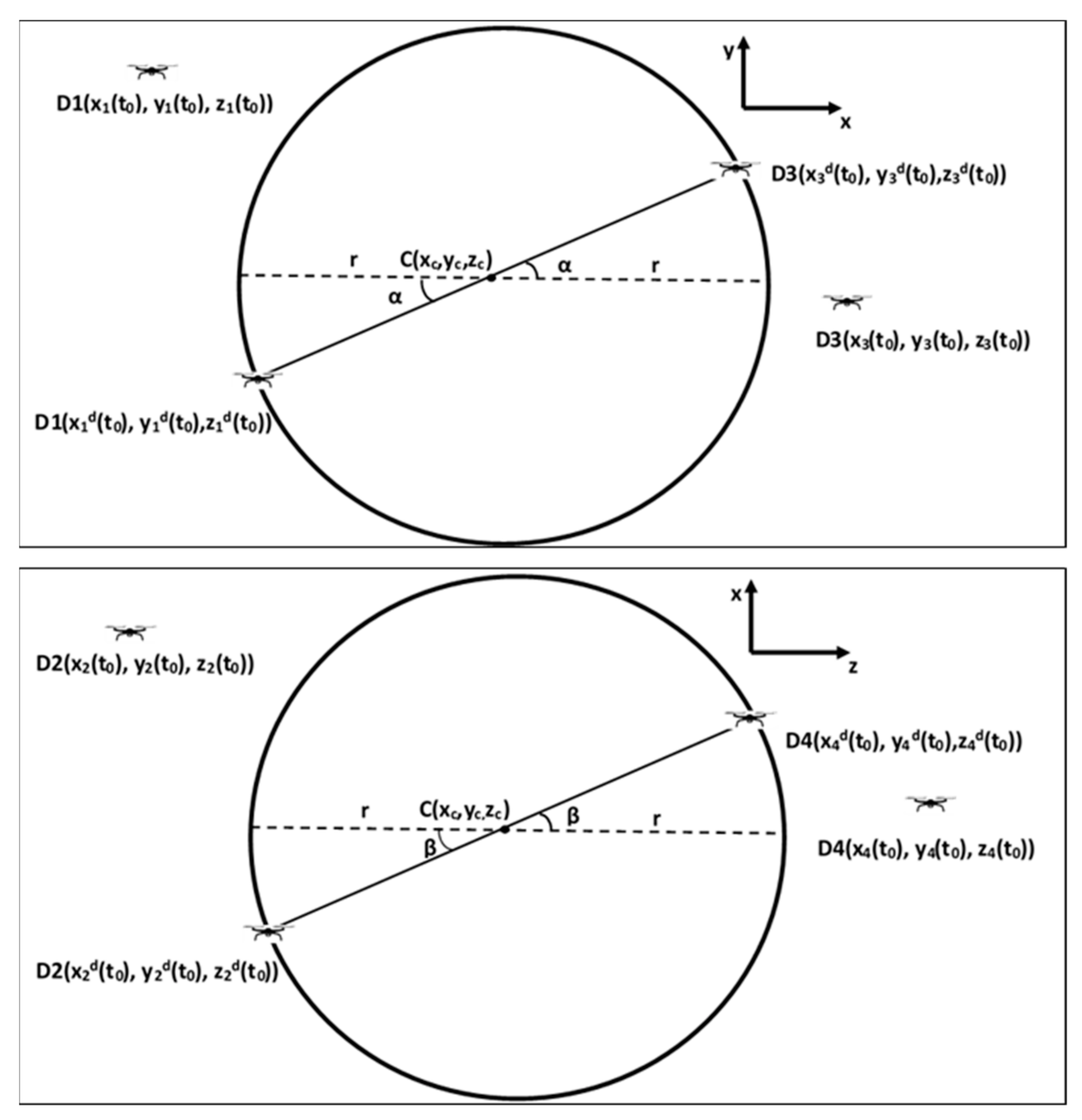
Figure 1. Initial and desired locations of the UAVs.
Drones 06 00417 g001
Figure 2. UAVs fly in the desired initial location with different received signal strengths.
Drones 06 00417 g002
Figure 3. UAVs move in a circular formation to receive the same RSSI value.
Drones 06 00417 g003
Figure 4. Flowchart of proposed localization method.
Drones 06 00417 g004
Figure 5. Rotation of UAVs and a line passing through augmented point and formation center.
Drones 06 00417 g005
Figure 6. Intersection of multiple lines, which gives the source location.
Drones 06 00417 g006
Figure 7. (a) Received power by D1 and D3, (b) received power by D2 and D4, and (c) power differences of each group.
Drones 06 00417 g007
Figure 8. Source localization in a noisy environment.
Drones 06 00417 g008
Table 1. Comparison of different localization techniques.
StudyMethodAdvantagesLimitation/Disadvantages
S. M. Denghan et al. [26]Differential RSSITransmit power value is not requiredNonlinear modeling for FIM and EKF
Hasanzade et al. [22]RSSI with EKFNoise reduction with EKFTransmit power value required, it is estimated with NN
Hasanzade et al. [22]RSSI with Particle FilterOnly one UAV is requiedHigh computational complexity of Partical Filter
Zhou et al. [19]Both RSSI and Visual localiationLocalization with BluetoothImages can be poor for some circumtances
Table 2. Localization error of RF source with different noise ratios.
Standard Deviation RatioMean Error
2%28.3 m
4%52.66 m
8%145.7 m
Publisher’s Note: MDPI stays neutral with regard to jurisdictional claims in published maps and institutional affiliations.