Article

Computer Vision Based Path Following for Autonomous Unmanned Aerial Systems in Unburied Pipeline Onshore Inspection

1
Department of Electronics Engineering, Federal Center for Technological Education of Rio de Janeiro, Rio de Janeiro 20271-110, Brazil
2
Department of Microsystems, Faculty of Technology, Natural Sciences and Maritime Sciences, University of South-Eastern Norway (USN), 3184 Borre, Norway
3
NORCE—Norwegian Research Centre, 5838 Bergen, Norway
4
Research Centre in Digitalization and Intelligent Robotics (CeDRI), Instituto Politécnico de Bragança, 5300-252 Bragança, Portugal
5
Laboratório para a Sustentabilidade e Tecnologia em Regiões de Montanha (SusTEC), Instituto Politécnico de Bragança, 5300-252 Bragança, Portugal
6
INESC TEC—Institute for Systems and Computer Engineering, Technology and Science, 4200-465 Porto, Portugal
*
Author to whom correspondence should be addressed.
Drones 2022, 6(12), 410; https://doi.org/10.3390/drones6120410
Submission received: 4 November 2022 / Revised: 30 November 2022 / Accepted: 9 December 2022 / Published: 14 December 2022
(This article belongs to the Section Drone Design and Development)

Abstract

:
Unmanned Aerial Systems (UAS) are becoming more attractive in diverse applications due to their efficiency in performing tasks with a reduced time execution, covering a larger area, and lowering human risks at harmful tasks. In the context of Oil & Gas (O&G), the scenario is even more attractive for the application of UAS for inspection activities due to the large extension of these facilities and the operational risks involved in the processes. Many authors proposed solutions to detect gas leaks regarding the onshore unburied pipeline structures. However, only a few addressed the navigation and tracking problem for the autonomous navigation of UAS over these structures. Most proposed solutions rely on traditional computer vision strategies for tracking. As a drawback, depending on lighting conditions, the obtained path line may be inaccurate, making a strategy to force the UAS to continue on the path necessary. Therefore, this research describes the potential of an autonomous UAS based on image processing technique and Convolutional Neural Network (CNN) strategy to navigate appropriately in complex unburied pipeline networks contributing to the monitoring procedure of the Oil & Gas Industry structures. A CNN is used to detect the pipe, while image processing techniques such as Canny edge detection and Hough Transform are used to detect the pipe line reference, which is used by a line following algorithm to guide the UAS along the pipe. The framework is assessed by a PX4 flight controller Software-in-The-Loop (SITL) simulations performed with the Robot Operating System (ROS) along with the Gazebo platform to simulate the proposed operational environment and verify the approach’s functionality as a proof of concept. Real tests were also conducted. The results showed that the solution is robust and feasible to deploy in this proposed task, achieving 72% of mean average precision on detecting different types of pipes and 0.0111 m of mean squared error on the path following with a drone 2 m away from a tube.

1. Introduction

Unmanned Aerial Systems (UAS) are becoming more attractive in diverse applications in society, being applied in security areas [1,2], small deliveries [3], military combat, photogrammetric applications [4], remote inspections [5,6], agriculture, among others. In general, the application of this resource aims to increase the efficiency of the task performed and reduce human risks at dangerous missions [7]. The UAS controlling process can be performed remotely (e.g., radio-controlled, via satellite) or autonomously. In addition, UAS typically performs GPS-based navigation. However, due to the constant changing in the environments, as well as the unmapped obstacles, by using only the GPS, the trajectory the UAS performs can be inaccurate and inefficient [8]. Thus, an intelligent strategy for autonomous movement is using image processing along with other sensors [9]. Computer Vision plays a vital role in increasing the autonomous functionalities of robotic systems [10]. By using cameras and image processing, it is possible to interpret situations/scenes and detect objects [11], being one of the main tools for controlling autonomous vehicles, performing tasks, or navigating.
In the literature, several researchers applied computer vision techniques to increase the automaticity level of robotic systems [12,13,14]. For instance, Khaloo et al. [15] presented a study on the application of UAS for inspecting dams and looking for breakpoints in these structures. Another application of autonomous inspection with UAS is presented in Vam et al. [16]. The authors proposed an autonomous inspection of an electrical substation, in which the UAS must be able to navigate the installation autonomously, carry out video inspections, and indicate the location that contains signs of degradation, serving as a basis for infrastructure inspection work as a whole.
UAS are being used in the most different missions that can be risky for humans or in tedious tasks that demand an outstanding level of attention [17]. In the context of large industrial parks, refineries, Gas & Oil processing units, the scenario is even more attractive for the application of UAS inspection activities [18]. As the dimension and extensions of these facilities are very large and with different human risks among the areas, the operator will be able to remain stationary in a safe area while monitoring the flight parameters during the inspection process with the UAS [19]. Note that the Oil & Gas industry has used Remotely Operated Vehicles (ROVs) since the 1970s to inspect and maintain underwater structures [20]. When the UAS is deployed for inspection in large structures, the inspection process can be sped up and is cost-efficient due to the reduction of engineering labor fees and risk minimization due to human errors [21]. For instance, the inspection of the pipeline corridors is still monitored by foot patrol, crewed vehicles, and air patrols with inspection personnel. The main objective is to prevent possible risk events. Therefore, these inspections must be carried out regularly. The work of Kus and Srinivasan [18] applied UAS to inspect external corrosion in refinery units visually. In both works of Ramos et al. [14] and [22], the authors presented the use and technical feasibility of the application of an autonomous vision-based UAS for messenger cable transfer in mooring tasks. Another UAS application in the Oil & Gas environment is presented [23]. They applied a multirotor UAS for small cargo transport between naval structures in their work.
As can be seen, novel robotic systems have been applied to O&G industry sector to move the traditional processes toward more autonomous operations [24]. As a result of this process, operational and human costs and effort can be reduced. Besides that, the safety of the operation can be enhanced [21].
Several works proposed solutions to inspect pipeline corridors. For instance, the authors of Wang et al. [25] used an Autonomous Underwater Vehicle (AUV) equipped with image-processing technology to detect the pipeline’s corners. Concerning onshore pipelines, there are different types of robots, and the locomotion style reflects directly in the robot’s performance for the pipeline inner inspection. A simple device called PIG was used to collect the data of the pipeline, which was proposed by Mazreah et al. [26]. Their robot was driven by oil or gas flow through the pipeline to perform the inspection. A wheel-type robot was proposed by Kakogawa et al. [27]. The wheel of their robot was used to touch the pipe wall. In Kwon et al. [28], the authors used a track type as an alternative solution to the wheeled robot.
This field of pipeline inspection has many challenges such as difficult areas to access and with significant human risk, classified areas, work at heights, among others. Regarding the use of UAS for this field of inspection, many authors proposed solutions to detect a gas leak in onshore pipelines [29,30]. For instance, in the work of Bretschneider et al. [31], the authors described a payload solution to detect gas leaks in unburied onshore pipelines. Their solution presented a combination of lasers and an electro-optical sensor. However, few works described solutions to the autonomous navigation solution to support pipeline corridors inspection and monitoring in the Oil & Gas industry.
The authors of Shukla et al. [32] developed an autonomous tracking and navigation controller for UAS to inspect straight oil and gas pipelines. Their work cannot handle curves in the pipeline corridors as a drawback. In [33], the authors showed an optimization strategy for UAS inspection of an oil and gas pipeline network. Their process used a mixed-integer nonlinear programming model to consider the constraints of the mission scenario and the safety performance. As can be seen, there is still space for improvements in inspection and monitoring solutions of unburied onshore pipeline corridors, especially regarding the autonomous navigation solutions for UAS.
Computer vision is one of the fastest-growing areas in the field of computing. The interpretation and transformation of data into useful information are complex tasks. In the area of pipelines inspection, image processing is often used to identify and detect parts inside the pipe [34]. There are a plenty of methods for corrosion and cracks region segmenting, such as morphological operations [35,36,37] and geometrical operations [38,39], segmentation methods [40,41], thresholding [42], and active contour [43]. For instance, morphological operations along with thresholding and labeling were used for corrosion inspection in [35]. Similarly, in the work of [37], the authors applied morphological-based edge detection in order to detect cracks in the pipeline. Recently, to overcome the necessity of a lot of steps of traditional image processing, deep learning arose as a prominent solution for the field of computer vision [44,45].
However, to the best of the authors’ knowledge, no works in the literature applied deep learning strategies as a tool to the navigation and control problem in the unburied pipeline networks. In the work of Xiaqian et al. [46], the authors proposed an autonomous navigation control strategy for tracking and inspecting linear horizontal structures of pipelines networks with UAS. They used traditional methods, such as Canny Edge Detector (CED) and the Probabilistic Hough Transformation (PHT) to identify the structures to the control input. They did not consider more complex scenarios with the pipeline networks and only considered the control problem.
Finally, the authors of Gomez et al. [30] performed an extended review of the requirements for small unmanned airborne systems applied to pipeline inspections and monitoring. Their paper concluded that UAS are reliable and can substitute traditional monitoring procedures such as foot patrolling and aerial surveys. Therefore, this research work describes the potential of an autonomous UAS along with a deep learning strategy to navigate appropriately to complex unburied pipelines networks, contributing to the monitoring and mapping procedure of these structures of the Oil & Gas Industry.
The related works summary is presented in Table 1.
In order to fill the presented gaps in autonomous onshore O&G unburied pipeline inspection with UAS, this study presents and evaluates a tracking strategy guided through computer vision. Machine Learning models combined with traditional pre-processing computer vision techniques are used to detect and classify the pipes, as well as finding the pipe line reference. A path following solution is then used to guide the UAS along the pipes. The main contributions of this research can be summarized as follows:
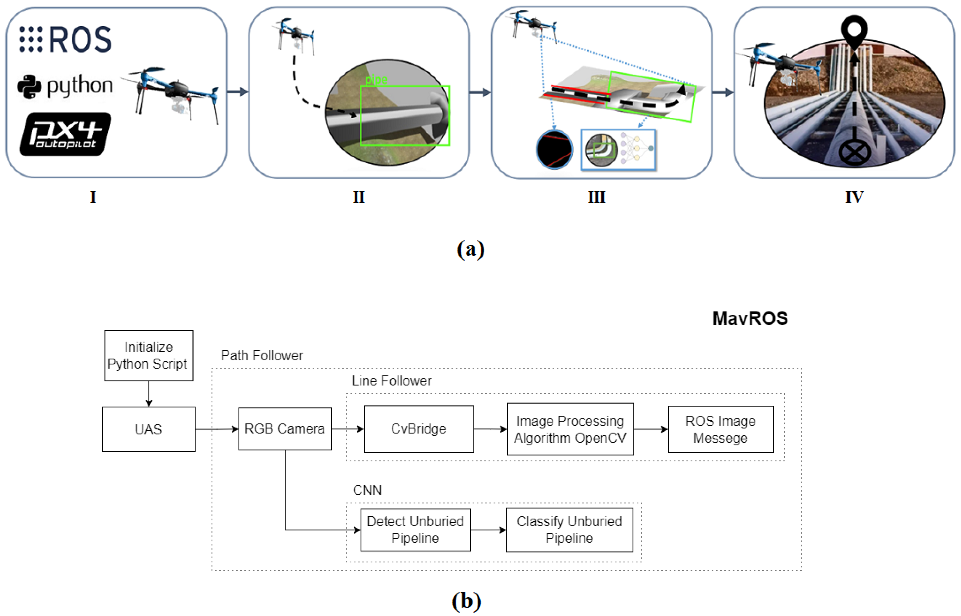
  • An object detection solution, with image processing and Convolution Neural Networks to detect different types of unburied pipes in onshore O&G installations;
  • A path-following solution to navigate the UAS over the extensive structures of unburied pipelines;
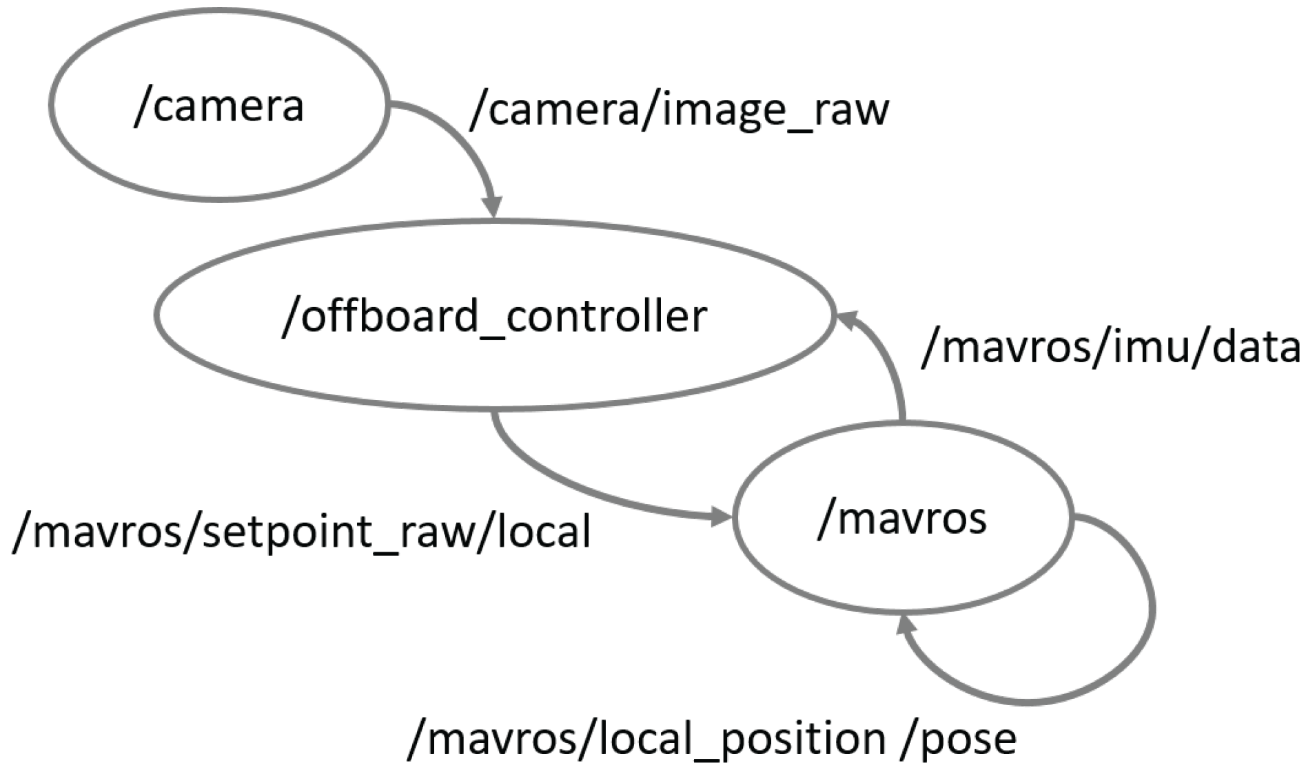
  • Implementation of the full solution using Robot Operating System and the PX4 flight control unit;
  • Software-In-The-Loop simulation environment to test similar solutions in a virtual O&G installation using Gazebo;
  • Test and evaluation of the proposed solution with a real drone to prove its functionality in a real application.

2. Materials and Methods

In this section, the problem formulation and the solution setup, as well as the object detection and path following solutions, will be presented.

2.1. Problem Formulation

This work intends to provide an automatic solution to track unburied pipelines in the O&G industry facilities with Unmanned Aerial Systems (UAS).
Figure 1 illustrates a detailed research flowchart and the general idea of the proposed solution. First, the framework ROS, hardware, and algorithms are initialized. Then, communication with the Flight Control Unit (FCU) PX4 is established to start the line-follower strategy. Note that the UAS uses a Convolutional Neural Network (CNN) model to detect and classify the unburied pipeline structure. After detecting a pipe, image processing techniques, such as Canny Edge Detection [50] and Hough transform [51], are used to find the line through the pipe that the UAS should follow. Through the use of ROS and Python scripts, it is possible to read the camera topic messages from the UAS, convert them to an OpenCV array with CvBrigde (i.e., ROS library), and process the information to define the robot positions setpoint. The detected line is used as a reference by the line following algorithm. These steps are repeated, including the CNN detection, which is called to assist the system as a tracking solution to make the application robust against light variations, for example. The hardware and algorithms are initialized along with ROS and the PX4 Flight Control Unit (FCU). Note that the position commands are parsed to the FCU through the MavROS package via MAVlink protocol.

2.2. Solution Setup

In the simulation, the camera images are made available by Gazebo through ROS topics and messages. A Python script converts these messages to an OpenCV array with CvBrigde (i.e., ROS library), see Figure 2, and sends it to PX4 with the MavROS package via MAVlink protocol. Therefore, the PX4 can stream the video, which is then processed by the solution presented in this work.
In the real implementation, the camera is already connected to the PX4, which transmits the camera images to the ground station. The ground station is responsible for processing the images and sending the path following commands to the UAS. The tasks carried out by the Ground Station could be easily implemented in a companion computer if on-board processing is desired.
In both applications, ROS and Python work in the ground station and FCU PX4. In the ground station, the edge/line detection runs as long as the CNN identifies a pipe to make the UAS go forward and indicates which side of the image is a curve to activate the Canny and Hough algorithms. The CNN feature is also used to approach the pipe once it is detected. With all these features, the UAS becomes capable of performing not only the proposed tracking pipeline task but other assignments such as surveillance and structure inspections.
The developed robotic system in ROS is presented in Figure 3. The solution presented in this work is implemented in the Off-board Controller, which processes the camera images and sends the desired commands to the flight controller through MavROS.
The controller was developed in Python language and using ROS packages [52], such as the MavROS. Note that the controller was designed for a PixHawk Px4 FCU [53].

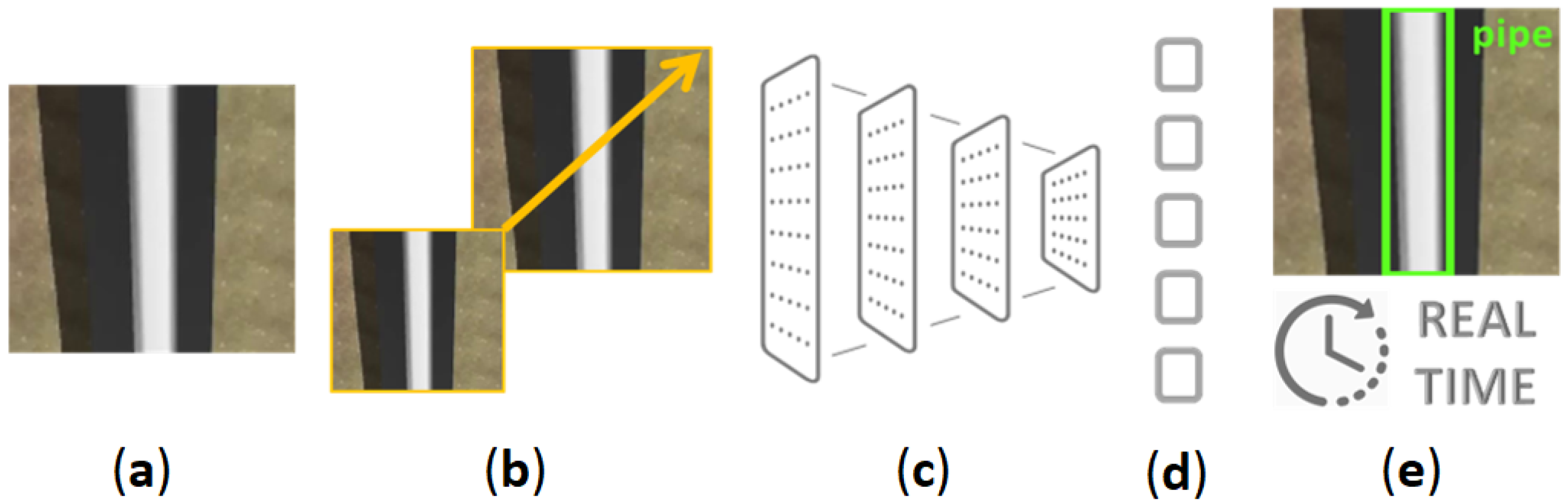
2.3. Yolov4 Neural Network

This work proposes using a You Only Look Once (YOLO) Neural Network to assist the UAS during the tracking strategy. According to [54], YOLO is a state-of-the-art real-time object detection system that is extremely fast and accurate. This network is a single-stage detector, which divides the image into regions, predictions bounding boxes, and probabilities, as illustrated in Figure 4.
YOLO architecture comprises 24 convolution layers responsible for extracting the image features and two fully connected layers that perform the output prediction of the bounding boxes’ coordinates and probability. The first 20 convolutional layers are pre-trained by the ImageNet 1000-class classification data set, which makes YOLO fast to train once just the four last layers are trained to detect the desired object [54].
The authors created a dataset [55] to train the YOLO model for recognizing industrial pipe since other well-known images datasets such as Microsoft Common Objects in Context (MS COCO) [56], ImageNet [57], and even open images v4 [58], do not have a specific O&G pipe class object. The authors’ dataset has 644 labeled pipe images, divided into real scenes and synthetic ones. The real images come from Google Images and videos search. The keywords used were O&G pipelines, pipeline images from drones, refinery, unburied pipes, and O&G company names, among others). The synthetic images were created in Blender [59] and Gazebo software. In this case, the UAS took almost all synthetic images using a Radio Control to fly above the pipes. Figure 5 gives a few image examples that compose the dataset. All the images are annotated using the open-source software [60]. After that, the data are augmented using crop, rotate, and resize techniques. Finally, the dataset is composed of 1243 labeled pipe images split into 1000 for training, 129 for validation, and 64 for testing.
The hyperparameters different from the YOLO default structure and other options of the model’s train are shown in Table 2. These hyperparameters are applied using rules of thumb discussed by Hinton et al. [61].
During the training, the image input with ground truth marks is resized to 448 × 448 (Figure 6a). Then, it is followed by convolutional and full connected layers (Figure 6b), which pass through a pooling process to generate a matrix with relevant data (Figure 6c). This matrix with the detection information is flattened (Figure 6d), and then the weight files are generated with good samples and ready to use for object detection (Figure 6e).
The CNNs can transform an original input layer by layer using convolutional and downsampling techniques to produce class scores for classification and regression purposes. In this sense, the CNN with YOLO layers and resizing takes the image and generates a vector (after the pooling) with the bounding box coordinates that might have the object and the network class with the probability of the object being in this bounding box. This detection runs in three layers 13 × 13, 26 × 26, and 52 × 52 (width and height). With all these features and the grid technique, YOLO can detect many objects in the same image with high efficiency, even more, when used with a non-max suppression algorithm which guarantees a clean detection based on each class. The reason is that all repeated detection of the same image is suppressed. Thus, YOLO is perfect to achieve the recognition task for online implementations [62].

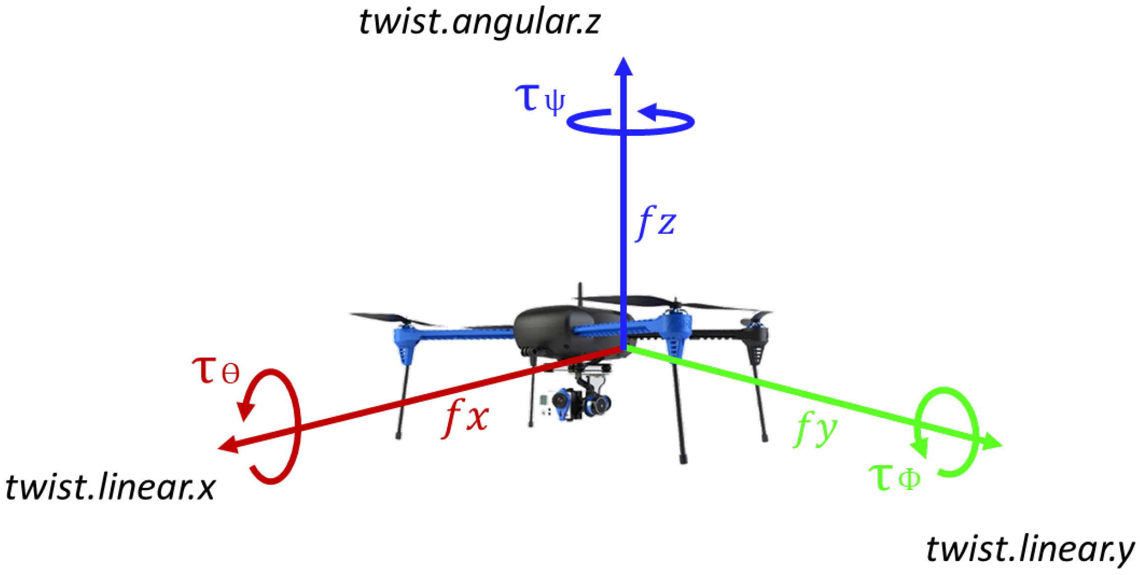
2.4. Quadrotor Model

The quadrotor model used in this work is based on that proposed by Brandão et al. [63]. The quadrotor rotation on its axis is given by the motor speed variation, and the generated inclination results in the vehicle displacement in any direction of space.
In this work, the altitude is kept constant and the commands sent to the flight control unit are the local forward and lateral velocities, as well as the angular speed around the z-axis ( u b = [ v x , v y , r ] ). Figure 7 illustrates the UAS local frame and the ROS messages used. The relationship between the commands ( u b ) and the position derivative of the UAS in the world frame ( P ˙ w ) is given by the following equation:
P ˙ w = R b w u b ,
where P ˙ w = [ x ˙ , y ˙ , ψ ˙ ] , x is the east position, y is north position, and ψ is the heading of the UAS. R b w is the rotation matrix from body to world frame, given by:
c o s ( ψ ) s i n ( ψ ) 0 s i n ( ψ ) c o s ( ψ ) 0 0 0 1 .

2.5. Pipe Follower

The image is first processed by the Canny edge detection algorithm [64]. This first stage performs the filtering of the image, i.e., giving the image locating and corners. This outcome goes to the Hough transform algorithm to be analyzed during the parameterization, as demonstrated in [65]. This image processing is a mechanism for extracting features from an image using a voting policy. Note that a single pixel can have an infinite number of lines passing through it. The authors refer to the work of [66] for more detailed information about this process.
This procedure specifies a narrow line represented by the angle θ from the normal and delimited by the distance ρ from the origin, as shown in Equation (5). In this equation, the distance corresponds to the geometry when applied in a way to consolidate a space of n points (Equation (6)). Note that the Hough space and the Cartesian coordinate can be transformed into each other. This process is illustrated in Figure 8.
The main objective of the Hough transform is to convert the image points into a line, a simple equation of a straight line (Equation (3)), and a polar equation (Equation (4)). Thus, it is possible to transform and curve or straight in points, Figure 8, and build an accumulator matrix A(N). Thus, this feature is based on mapping the digital image pixel into the parameter space. With an N-dimensional accumulator, pixel organization can be quantized and added into an accumulator matrix A(N). Inside this matrix, the highest peaks detected are the higher potential equation of straight line detection, like a voting system:
Y = a X + b
σ = X c o s ( θ ) + Y s i n ( θ )
Note that it is possible to identify a line by the number of intersections, that is, in case the number of intersections is greater, the more accurate is the probability to have a line in the analyzed image area. For this work, we set up a threshold with a minimum amount of intersections:
y = ( cos θ sin θ ) x + ( ρ sin θ )
ρ θ = X n · cos θ + Y n · sin θ
Note that the polar coordinate ( ρ θ , θ ) represents a line passing through a point ( X 1 , Y 1 ) . From Figure 8, it is possible to obtain Equation (7). Thus, by making the Hough Transform into a single line, the path (parameters ρ and θ ) can be obtained:
X 1 = ρ · cos θ , a n d Y 1 = ρ · sin θ
The controller is responsible for regulating speed, direction, and orientation. It receives the parameters ρ and θ and calculates the necessary control inputs to assure that the UAS flies with the line between the desired limits. Note that, through the line readings as a basis and delimiting a threshold to contain the continuous correction of the UAS direction, the angle α of Equation (8) is obtained by correlating the line generated by the code, being an angular fault prioritization. Note that the points ( X 1 , Y 1 ) and ( X 2 , Y 2 ) are drawn by the problem to concatenate them. The proposed strategy marks the image processed by the camera in order to optimize the values obtained, overwriting the line with one generated directly by the algorithm:
α = 1 · ( arctan ( ( Y 2 Y 1 ) ( X 2 X 1 ) )
Basically, the controller first rotates the UAS around its z-axis to have the detected line normal to the image horizontal plane. Then, the drone moves on its lateral axis to position the line within the predefined limits. Finally, it moves the drone forward along the pipe line. This process is repeated on every algorithm loop.

3. Results and Discussion

In this section, the CNN model training results are presented, as well as the tests evaluated in the simulation environment and in real flights.

3.1. YOLO Training and Results

In order to train YOLO’s model, the authors used Google Colab, a web-hosted Jupyter notebook service, and [67] as a guideline for the task. The amount of RAM disposable was 12 GB and 16 GB TPU Tesla T4 was also provided by the application. After the training, the weights are locally stored and used in the ground control station.
In Figure 9, the learning curve of the YOLO’s training results for the bounding boxes detection and the object classification, respectively, are presented. The YOLO model was trained with a dataset containing both the simulated and real images. It is possible to observe that the training took around 280 epochs. The training took approximately 4 h in the computer with configuration described in the previous paragraph.
Figure 10 displays the Precision–Recall curve, which presents the tradeoff between precision and recall for different threshold levels, and the mean average precision (inside the legend box). In this application, the threshold should be selected based on the mission objective. For example, if the objective is to inspect every pipe in the plant, it seems wise to choose a lower threshold and risk inspecting objects that are not pipes but being sure that every pipe is inspected. If a quick and general inspection is needed, a high threshold may be chosen.
Figure 11 shows some results of the trained model when facing the testing images from the dataset. It is possible to see that the confidence of the object classification is very high (i.e., close to 90%). This result is even in the third image (i.e., the widest one), where a wall can easily be misunderstood as a pipe from above. The trained model identifies just the two tubes. In addition, note that this image is angled, which makes it harder to precisely mark the bounding box.
Table 3 presents the confusion matrix results from the trained model facing the testing dataset for the threshold chosen for the simulated and real flight tests. During the application, the model input is taken from the UAS /camera node simulated by ROS.

3.2. Simulation Tests

In order to first evaluate the proposed strategy safely, the Gazebo software was used to simulate an Oil & Gas pipeline inspection environment (Figure 12).
The Ground Station (GCS) receives the information from a telemetry module available on both the computer and the UAS, using the MAVLink communication protocol. The PX4 software, which runs on the PixHawk flight controller hardware, is responsible for acquiring information from the peripheral sensors and modifying these values in the actuators to which it has access. The GCS runs the operating system Ubuntu 18.04.4 LTS 64 bits, and it has an Intel® Core™ i7-5500U CPU @ 2.40GHz × 4, Intel® HD Graphics 5500 (Broadwell GT2) with 15.6 Gb RAM.
The takeoff height was around 3 m for safety reasons. The UAS uses the predetermined height as a checkpoint to start the path follower script, maintaining its altitude during the inspection. Figure 13 presents the UAS approaching the pipeline and starting to follow the unburied pipeline using the line follower methodology.
This figure gives the outcomes from the steps of the path following algorithm, which uses the difference between the red line and the blue line limits as the error. The red line on the output shows the middle term between the two lines detected, corresponding to the sides of the pipe isolated by using a grayscale technique, filtering and smoothing the original image.
The next set of test (Figure 14) in the Gazebo simulation was to perform straight-line and curves in order to verify the performance of the image processing and Yolov4 algorithms. Note that the path follower was able to satisfactory perform the tasks.
A video of the proposed strategy working in the simulation environment is available online (https://github.com/LucasSousaENG/Pipeline-Inspection/, accessed on 3 November 2022).

3.3. Real Flight Tests

After testing the system in a simulated world, the authors also decided to test the model in a real-world constrained scenario to show the robustness of the proposed methodology. The constraints are just to preserve the safety of the UAS. A safe flight distance from the pipes was set to 10 m high, and the experiments were outdoors but not affected by strong winds.
Another simplification was on the curve observed on the pipelines. The authors decided to first test the proposed methodology just with slight curved pipelines or completely straight ones. Note that 90º degree curves are dismissed in these tests.
For the test, the Bebop Parrot quadrotor was used (Figure 15) with the FCU from PixHawk PX4, due to the MavROS ready-to-use offboard controller. This is the same setup as the simulation presented in the previous section.
The test was performed on a water pipe shown in Figure 16, used to supply an artificial lake at UNIFEI (Federal University of Itajubá), located in Minas Gerais state, Brazil. The pipe has a diameter of 6 inches and a straight part of around 15 m length. During the test, the weather was sunny and without winds.
The results of the image processing are presented in Figure 17. Note that the red line inside the blue line limits shows that the UAS is able to keep the detected line (red) very close to the reference line (yellow). Figure 17a presents the first image processing step, which transforms the original image in a binary image. The second step is the application of the Canny Detection algorithm, whose image output can be seen in Figure 17b. Finally, the pipe line is calculated and can be observed in Figure 17c in red. In Figure 17d, the output of the CNN model, which detects the pipes, is shown.
Figure 18a presents the path follower behavior in the practical experiment. It is possible to observe satisfactory performance in terms of a very small error deviation from the guideline of around 0.0111 m. In Figure 18b, it is also possible to analyze the error between the pipe location and the agent path during the tests.
It is important to highlight that the tests in this real environment were performed in a controlled scenario, where lighting conditions and winds did not harm the process. As a quality comparison, Table 4 presents a few differences between the simulation and real environment tests. The obtained results demonstrated the technical feasibility of the proposed approach to be applied for autonomous inspection of the unburied pipeline structures in O&G facilities. Note that the CNN performance is better in the real-world test. This can be explained due to the low simulation world image definition that is the consequence of the pipe size and Gazebo image rendering power. On the other side, in the simulated environment, the tracking error is smaller because of the perfection of the line and other element absence, such as a wall.

4. Conclusions

This work proposed a solution composed by a computer vision method based on CNN along with classical image pre-processing techniques to autonomously guide a UAS through unburied pipelines of onshore O&G facilities during inspection tasks. The CNN is used to detect the pipes, while classical image processing techniques are used to extract the pipe reference line. The line follower strategy is based on Hough transform to perform the line tracking during the straight parts, reaching 0.0111 m of mean squared error in real flight tests. Tests were also performed in the Gazebo virtual environment, and the outcomes showed that the proposed approach succeeded in accomplishing the mission. The robot used in the simulation flew over all the pipelines safely and thoroughly autonomously. Regarding the CNN results, the trained model was able to reach a mean average precision of 72% for the test dataset. The model can possibly achieve a better performer by fine-tuning hyperparameters or investigating other training techniques, such as transfer learning. The authors chose to not fine-tune the model as the CNN was not the focus of the work and that this simple implementation resulted in satisfactory performance in both simulated and real flight tests. As future work, the solution should be embedded in a companion computer, allowing the complete onboard processing. In addition, some improvements, such as only making the line detection inside the detected pipe bounding box, should be considered. Finally, more advanced control strategies, such as trajectory tracking with Model Predictive Control for constant speed along the pipe can be investigated.

Author Contributions

Conceptualization, Y.M.R.d.S., F.A.A.A., L.S. and M.F.P.; methodology, Y.M.R.d.S., G.G.R.d.C. and M.F.P.; validation, G.G.R.d.C.; formal analysis, G.B., M.F.P. and J.L.; investigation, Y.M.R.d.S., L.S., G.G.R.d.C. and M.F.P.; writing—original draft preparation, Y.M.R.d.S., L.S., G.G.R.d.C. and M.F.P.; writing—review and editing, J.T.D., M.F.P. and F.A.A.A.; visualization, G.B., M.F.P., J.L. and J.T.D.; supervision, F.A.A.A., M.F.P. and J.L.; project administration, M.F.P.; funding acquisition, M.F.P. and F.A.A.A. All authors have read and agreed with the submission of the current manuscript version.

Funding

This research received no external funding.

Data Availability Statement

The source-codes are openly available in https://github.com/LucasSousaENG/Pipeline-Inspection/, accessed on 3 November 2022.

Acknowledgments

The authors would like to thank the following Brazilian Agencies CEFET-RJ, CAPES, CNPq, and FAPERJ. In addition, the authors also want to thank the Research Centre in Digitalization and Intelligent Robotics (CeDRI), IPB, Laboratório para a Sustentabilidade e Tecnologia em Regiões de Montanha (SusTEC), IPB, Portugal, and INESC Technology and Science, Porto, Portugal.

Conflicts of Interest

Text.The authors declare no conflict of interest.

Abbreviations

The following abbreviations are used in this manuscript:
MDPIMultidisciplinary Digital Publishing Institute
AUVAutonomous Underwater Vehicle
CEDCanny Edge Detector
CNNConvolutional Neural Network
LFALine Follower Algorithm
PIDProportional Integral Derivative
MS COCOMicrosoft Common Objects in Context
UASUnmanned Aerial System
UAVUnmanned Aerial Vehicle
ROSRobotic Operating System
SITLSoftware in the Loop
YOLOYou Only Look Once

References

  1. Pinto, M.F.; Melo, A.G.; Marcato, A.L.; Urdiales, C. Case-based reasoning approach applied to surveillance system using an autonomous unmanned aerial vehicle. In Proceedings of the 2017 IEEE 26th International Symposium on Industrial Electronics (ISIE), Edinburgh, UK, 19–21 June 2017; pp. 1324–1329. [Google Scholar]
  2. Pinto, M.F.; Coelho, F.O.; De Souza, J.P.; Melo, A.G.; Marcato, A.L.; Urdiales, C. Ekf design for online trajectory prediction of a moving object detected onboard of a uav. In Proceedings of the 2018 13th APCA International Conference on Automatic Control and Soft Computing (CONTROLO), Ponta Delgada, Portugal, 4–6 June 2018; pp. 407–412. [Google Scholar]
  3. Madridano, Á.; Al-Kaff, A.; Martín, D.; de la Escalera, A. 3d trajectory planning method for uavs swarm in building emergencies. Sensors 2020, 20, 642. [Google Scholar] [CrossRef] [PubMed]
  4. Melo, A.G.; Pinto, M.F.; Marcato, A.L.; Honório, L.M.; Coelho, F.O. Dynamic Optimization and Heuristics Based Online Coverage Path Planning in 3D Environment for UAVs. Sensors 2021, 21, 1108. [Google Scholar] [CrossRef] [PubMed]
  5. Melo, A.G.; Pinto, M.F.; Honorio, L.M.; Dias, F.M.; Masson, J.E. 3D Correspondence and Point Projection Method for Structures Deformation Analysis. IEEE Access 2020, 8, 177823–177836. [Google Scholar] [CrossRef]
  6. Pinto, M.F.; Honorio, L.M.; Melo, A.; Marcato, A.L. A Robotic Cognitive Architecture for Slope and Dam Inspections. Sensors 2020, 20, 4579. [Google Scholar] [CrossRef]
  7. Pinto, M.F.; Honório, L.M.; Marcato, A.L.; Dantas, M.A.; Melo, A.G.; Capretz, M.; Urdiales, C. ARCog: An Aerial Robotics Cognitive Architecture. Robotica 2020, 39, 483–502. [Google Scholar] [CrossRef]
  8. Dijkshoorn, N.; Visser, A. Integrating sensor and motion models to localize an autonomous ar. drone. Int. J. Micro Air Veh. 2011, 3, 183–200. [Google Scholar] [CrossRef]
  9. Tang, D.; Kou, K.; Tang, Y. Autolanding System of Shipborne UAV Based on Fusion of INS, CDGPS and Vision-Based Navigation. In Advances in Guidance, Navigation and Control; Springer: Berlin/Heidelberg, Germany, 2022; pp. 1609–1618. [Google Scholar]
  10. Kakaletsis, E.; Symeonidis, C.; Tzelepi, M.; Mademlis, I.; Tefas, A.; Nikolaidis, N.; Pitas, I. Computer Vision for Autonomous UAV Flight Safety: An Overview and a Vision-based Safe Landing Pipeline Example. ACM Comput. Surv. (CSUR) 2021, 54, 1–37. [Google Scholar] [CrossRef]
  11. Coelho, F.O.; Pinto, M.F.; Souza, J.P.C.; Marcato, A.L. Hybrid Methodology for Path Planning and Computational Vision Applied to Autonomous Mission: A New Approach. Robotica 2020, 38, 1000–1018. [Google Scholar] [CrossRef]
  12. Biundini, I.Z.; Melo, A.G.; Pinto, M.F.; Marins, G.M.; Marcato, A.L.; Honorio, L.M. Coverage path planning optimization for slopes and dams inspection. In Iberian Robotics Conference; Springer: Cham, Switzerland, 2019; pp. 513–523. [Google Scholar]
  13. Coelho, F.O.; Carvalho, J.P.; Pinto, M.F.; Marcato, A.L. Ekf and computer vision for mobile robot localization. In Proceedings of the 2018 13th APCA International Conference on Automatic Control and Soft Computing (CONTROLO), Ponta Delgada, Portugal, 4–6 June 2018; pp. 148–153. [Google Scholar]
  14. Ramos, G.S.; Pinto, M.F.; Coelho, F.O.; Honório, L.M.; Haddad, D.B. Hybrid methodology based on computational vision and sensor fusion for assisting autonomous UAV on offshore messenger cable transfer operation. Robotica 2022, 40, 1–29. [Google Scholar] [CrossRef]
  15. Khaloo, A.; Lattanzi, D.; Jachimowicz, A.; Devaney, C. Utilizing UAV and 3D computer vision for visual inspection of a large gravity dam. Front. Built Environ. 2018, 4, 31. [Google Scholar] [CrossRef]
  16. Van Dam, J.; Krasne, A.; Gabbard, J.L. Drone-based augmented reality platform for bridge inspection: Effect of ar cue design on visual search tasks. In Proceedings of the 2020 IEEE Conference on Virtual Reality and 3D User Interfaces Abstracts and Workshops (VRW), Atlanta, GA, USA, 22–26 March 2020; pp. 201–204. [Google Scholar]
  17. Biundini, I.Z.; Pinto, M.F.; Melo, A.G.; Marcato, A.L.; Honorio, L.M. Coverage Path Planning Optimization Based on Point Cloud for Structural Inspection. In Frontiers in Nature-Inspired Industrial Optimization; Springer: Berlin/Heidelberg, Germany, 2022; pp. 141–156. [Google Scholar]
  18. Kus, S.; Srinivasan, S. Remote, Visual Inspection and Digital Analysis for External Corrosion Characterization in Refinery Unit Applications. In Proceedings of the CORROSION 2021, Online, 19–30 April 2021. [Google Scholar]
  19. Nikolic, J.; Burri, M.; Rehder, J.; Leutenegger, S.; Huerzeler, C.; Siegwart, R. A UAV system for inspection of industrial facilities. In Proceedings of the 2013 IEEE Aerospace Conference, Big Sky, MT, USA, 2–9 March 2013; pp. 1–8. [Google Scholar]
  20. Petillot, Y.R.; Antonelli, G.; Casalino, G.; Ferreira, F. Underwater Robots: From Remotely Operated Vehicles to Intervention-Autonomous Underwater Vehicles. IEEE Robot. Autom. Mag. 2019, 26, 94–101. [Google Scholar] [CrossRef]
  21. Yu, L.; Yang, E.; Ren, P.; Luo, C.; Dobie, G.; Gu, D.; Yan, X. Inspection robots in oil and gas industry: A review of current solutions and future trends. In Proceedings of the 2019 25th International Conference on Automation and Computing (ICAC), Lancaster, UK, 5–7 September 2019; pp. 1–6. [Google Scholar]
  22. Ramos, G.; Pinto, M.; de Souza, E.; Machado, G.; de Castro, G. Technical and Economic Feasibility Study for Implementing a Novel Mooring-Assisting Methodology in Offloading Operations Using Autonomous Unmanned Aerial Vehicles. SPE Prod. Oper. 2022, 37, 72–87. [Google Scholar] [CrossRef]
  23. Frederiksen, M.; Knudsen, M. Drones for Offshore and Maritime Missions: Opportunities and Barriers; Center for Integrative Innovation Management, University of Southern Denmark, SDU: Odense, Denmark, 2018. [Google Scholar]
  24. Durdevic, P.; Ortiz-Arroyo, D.; Li, S.; Yang, Z. Vision aided navigation of a quad-rotor for autonomous wind-farm inspection. IFAC-PapersOnLine 2019, 52, 61–66. [Google Scholar] [CrossRef]
  25. Wang, C.; Cui, L. The Implementation of Automatic Inspection Algorithm for Underwater Vehicles Based on Hough Transform. In Proceedings of the 2018 7th International Conference on Sustainable Energy and Environment Engineering (ICSEEE 2018); Atlantis Press: Paris, France, 2019; pp. 459–464. [Google Scholar]
  26. Mazreah, A.A.; Alnaimi, F.B.I.; Sahari, K.S.M. Novel design for PIG to eliminate the effect of hydraulic transients in oil and gas pipelines. J. Pet. Sci. Eng. 2017, 156, 250–257. [Google Scholar] [CrossRef]
  27. Kakogawa, A.; Ma, S. Design of a multilink-articulated wheeled pipeline inspection robot using only passive elastic joints. Adv. Robot. 2018, 32, 37–50. [Google Scholar] [CrossRef]
  28. Kwon, Y.S.; Yi, B.J. Design and motion planning of a two-module collaborative indoor pipeline inspection robot. IEEE Trans. Robot. 2012, 28, 681–696. [Google Scholar] [CrossRef]
  29. Iwaszenko, S.; Kalisz, P.; Słota, M.; Rudzki, A. Detection of natural gas leakages using a laser-based methane sensor and uav. Remote Sens. 2021, 13, 510. [Google Scholar] [CrossRef]
  30. Gómez, C.; Green, D.R. Small unmanned airborne systems to support oil and gas pipeline monitoring and mapping. Arab. J. Geosci. 2017, 10, 1–17. [Google Scholar] [CrossRef]
  31. Bretschneider, T.R.; Shetti, K. UAV-based gas pipeline leak detection. In Proceedings of the ARCS 2015, Porto, Portugal, 24–27 March 2015. [Google Scholar]
  32. Shukla, A.; Xiaoqian, H.; Karki, H. Autonomous tracking and navigation controller for an unmanned aerial vehicle based on visual data for inspection of oil and gas pipelines. In Proceedings of the 2016 16th International Conference on Control, Automation and Systems (ICCAS), Gyeongju, Republic of Korea, 16–19 October 2016; pp. 194–200. [Google Scholar]
  33. Yan, Y.; Liang, Y.; Zhang, H.; Zhang, W.; Feng, H.; Wang, B.; Liao, Q. A two-stage optimization method for unmanned aerial vehicle inspection of an oil and gas pipeline network. Pet. Sci. 2019, 16, 458–468. [Google Scholar] [CrossRef]
  34. Mangayarkarasi, N.; Raghuraman, G.; Kavitha, S. Influence of computer vision and iot for pipeline inspection-a review. In Proceedings of the 2019 International Conference on Computational Intelligence in Data Science (ICCIDS), Chennai, India, 21–23 February 2019; pp. 1–6. [Google Scholar]
  35. Motamedi, M.; Faramarzi, F.; Duran, O. New concept for corrosion inspection of urban pipeline networks by digital image processing. In Proceedings of the IECON 2012—38th Annual Conference on IEEE Industrial Electronics Society, Montreal, QC, Canada, 25–28 October 2012; pp. 1551–1556. [Google Scholar]
  36. Bondada, V.; Pratihar, D.K.; Kumar, C.S. Detection and quantitative assessment of corrosion on pipelines through image analysis. Procedia Comput. Sci. 2018, 133, 804–811. [Google Scholar] [CrossRef]
  37. Prema Kirubakaran, A.; Murali Krishna, I. Pipeline crack detection using mathematical morphological operator. In Knowledge Computing and its Applications; Springer: Berlin/Heidelberg, Germany, 2018; pp. 29–46. [Google Scholar]
  38. Su, T.C.; Yang, M.D. Application of morphological segmentation to leaking defect detection in sewer pipelines. Sensors 2014, 14, 8686–8704. [Google Scholar] [CrossRef] [PubMed]
  39. Sinha, S.K.; Fieguth, P.W. Morphological segmentation and classification of underground pipe images. Mach. Vis. Appl. 2006, 17, 21–31. [Google Scholar] [CrossRef]
  40. Sinha, S.K.; Fieguth, P.W. Segmentation of buried concrete pipe images. Autom. Constr. 2006, 15, 47–57. [Google Scholar] [CrossRef]
  41. Su, T.C. Segmentation of crack and open joint in sewer pipelines based on CCTV inspection images. In Proceedings of the 2015 AASRI International Conference on Circuits and Systems, Paris, France, 9–10 August 2015; Volume 2. [Google Scholar]
  42. Ting, L.L.; Tey, J.Y.; Tan, A.C.; King, Y.J.; Abd Rahman, F. Water leak location based on improved dual-tree complex wavelet transform with soft thresholding de-noising. Appl. Acoust. 2021, 174, 107751. [Google Scholar] [CrossRef]
  43. Hawari, A.; Alamin, M.; Alkadour, F.; Elmasry, M.; Zayed, T. Automated defect detection tool for closed circuit television (cctv) inspected sewer pipelines. Autom. Constr. 2018, 89, 99–109. [Google Scholar] [CrossRef]
  44. Kumar, S.S.; Abraham, D.M.; Jahanshahi, M.R.; Iseley, T.; Starr, J. Automated defect classification in sewer closed circuit television inspections using deep convolutional neural networks. Autom. Constr. 2018, 91, 273–283. [Google Scholar] [CrossRef]
  45. Yin, X.; Chen, Y.; Bouferguene, A.; Zaman, H.; Al-Hussein, M.; Kurach, L. A deep learning-based framework for an automated defect detection system for sewer pipes. Autom. Constr. 2020, 109, 102967. [Google Scholar] [CrossRef]
  46. Xiaoqian, H.; Karki, H.; Shukla, A.; Xiaoxiong, Z. Variant PID controller design for autonomous visual tracking of oil and gas pipelines via an unmanned aerial vehicle. In Proceedings of the 2017 17th International Conference on Control, Automation and Systems (ICCAS), Jeju, Republic of Korea, 18–21 October 2017; pp. 368–372. [Google Scholar]
  47. Basso, M.; Pignaton de Freitas, E. A UAV guidance system using crop row detection and line follower algorithms. J. Intell. Robot. Syst. 2020, 97, 605–621. [Google Scholar] [CrossRef]
  48. Okoli, J.; Ubochi, B. Autonomous Robot for Gas Pipeline Inspection and Leak Detection. Int. J. Comput. Digit. Syst. 2022, 11, 811–820. [Google Scholar] [CrossRef]
  49. Santa Maria, T.H.; Pusssente, G.A.N.; Marcato, A.L.M.; de Aguiar, E.P. NMPC controller applied to an UAV Path Following Problem. In Proceedings of the 2020 Latin American Robotics Symposium (LARS), 2020 Brazilian Symposium on Robotics (SBR) and 2020 Workshop on Robotics in Education (WRE), Natal, Brazil, 9–12 November 2020; pp. 1–6. [Google Scholar]
  50. Canny, J. A computational approach to edge detection. IEEE Trans. Pattern Anal. Mach. Intell. 1986, 679–698. [Google Scholar] [CrossRef]
  51. Ballard, D.H. Generalizing the Hough transform to detect arbitrary shapes. Pattern Recognit. 1981, 13, 111–122. [Google Scholar] [CrossRef]
  52. Quigley, M.; Conley, K.; Gerkey, B.; Faust, J.; Foote, T.; Leibs, J.; Wheeler, R.; Ng, A.Y. ROS: An open-source Robot Operating System. In Proceedings of the ICRA Workshop on Open Source Software, Kobe, Japan, 12–17 May 2009; Volume 3, p. 5. [Google Scholar]
  53. Ardupilot. APM Planner 2. 2020. Available online: https://ardupilot.org/planner2/ (accessed on 9 June 2020).
  54. Redmon, J.; Divvala, S.; Girshick, R.; Farhadi, A. You only look once: Unified, real-time object detection. In Proceedings of the IEEE Conference on Computer Vision and Pattern Recognition, Las Vegas, NV, USA, 27–30 June 2016; pp. 779–788. [Google Scholar]
  55. Silva, Y.; Sousa, L.; Souza, C. Pipeline Recognition for Drone Navegation. IEEE Dataport 2022. [Google Scholar] [CrossRef]
  56. Lin, T.Y.; Maire, M.; Belongie, S.; Hays, J.; Perona, P.; Ramanan, D.; Dollár, P.; Zitnick, C.L. Microsoft coco: Common objects in context. In Proceedings of the European Conference on Computer Vision, Zurich, Switzerland, 6–12 September 2014; Springer: Cham, Switzerland, 2014; pp. 740–755. [Google Scholar]
  57. Deng, J.; Dong, W.; Socher, R.; Li, L.J.; Li, K.; Fei-Fei, L. Imagenet: A large-scale hierarchical image database. In Proceedings of the 2009 IEEE Conference on Computer Vision and Pattern Recognition, Miami, FL, USA, 22–24 June 2009; pp. 248–255. [Google Scholar]
  58. Kuznetsova, A.; Rom, H.; Alldrin, N.; Uijlings, J.; Krasin, I.; Pont-Tuset, J.; Kamali, S.; Popov, S.; Malloci, M.; Kolesnikov, A.; et al. The open images dataset v4. Int. J. Comput. Vis. 2020, 128, 1956–1981. [Google Scholar] [CrossRef]
  59. Community, B.O. Blender—A 3D Modelling and Rendering Package; Blender Foundation, Stichting Blender Foundation: Amsterdam, The Netherlands, 2018. [Google Scholar]
  60. Tzutalin, D. LabelImg. GitHub Repos. 2015, 6. Available online: https://github.com/tzutalin/labelImg (accessed on 20 June 2022).
  61. Hinton, G.E. A practical guide to training restricted Boltzmann machines. In Neural Networks: Tricks of the Trade; Springer: Berlin/Heidelberg, Germany, 2012; pp. 599–619. [Google Scholar]
  62. Ćorović, A.; Ilić, V.; Ðurić, S.; Marijan, M.; Pavković, B. The Real-Time Detection of Traffic Participants Using YOLO Algorithm. In Proceedings of the 2018 26th Telecommunications Forum (TELFOR), Belgrade, Serbia, 20–21 November 2018; pp. 1–4. [Google Scholar] [CrossRef]
  63. Brandao, A.S.; Martins, F.N.; Soneguetti, H.B. A vision-based line following strategy for an autonomous UAV. In Proceedings of the 2015 12th International Conference on Informatics in Control, Automation and Robotics (ICINCO), Colmar, France, 21–23 July 2015; Volume 2, pp. 314–319. [Google Scholar]
  64. Ding, L.; Goshtasby, A. On the Canny edge detector. Pattern Recognit. 2001, 34, 721–725. [Google Scholar] [CrossRef]
  65. Duda, R.O.; Hart, P.E. Use of the Hough transformation to detect lines and curves in pictures. Commun. ACM 1972, 15, 11–15. [Google Scholar] [CrossRef]
  66. Mu, Z.; Li, Z. Intelligent tracking car path planning based on Hough transform and improved PID algorithm. In Proceedings of the 2018 5th International Conference on Systems and Informatics, Nanjing, China, 10–12 November 2018; pp. 24–28. [Google Scholar]
  67. Bisong, E. Building Machine Learning and Deep Learning Models on Google Cloud Platform: A Comprehensive Guide for Beginners; Apress: Berkeley, CA, USA, 2019; pp. 59–64. [Google Scholar]
Figure 1. (a) General Idea: I. Initializing the ROS environment, algorithms, and communication with PX4 FCU. II. UAS approaching the pipe structure. III. Image processing algorithms and CNN models. IV. Path Follower Strategy. (b) Research flowchart.
Drones 06 00410 g001
Figure 2. CvBridge/OpenCV communication overall flowchart.
Drones 06 00410 g002
Figure 3. ROS active nodes and messages.
Drones 06 00410 g003
Figure 4. YOLO Object Detection Process applied in the Proposed Scenario. (a) input pipeline image; (b) YOLO S x S image division; (c) merge boxes that contain the pipe; (d) generated bounding box.
Drones 06 00410 g004
Figure 5. A few annotated images that compose the developed dataset of the authors, which is available at [55].
Drones 06 00410 g005
Figure 6. YOLO overall idea. (a) input image; (b) resizing; (b) convolutional and full connected layers; (c) polling; (d) flattening; (e) object detection phase.
Drones 06 00410 g006
Figure 7. Quadrotor model (colored) and movement ROS topic (black).
Drones 06 00410 g007
Figure 8. Hough points.
Drones 06 00410 g008
Figure 9. Box and object loss through the 282 epochs of training. (a) bounding box regression loss (Mean Squared Error); (b) confidence of object (Binary Cross Entropy).
Drones 06 00410 g009
Figure 10. Precision vs. Recall curve.
Drones 06 00410 g010
Figure 11. Trained model pipe recognition with some testing dataset images. The YOLOv4 algorithm performs the automatic label and the confidence level for object classification. The bounding box did not describe the object’s spatial location well in the bottom image, but the algorithm was able to classify it.
Drones 06 00410 g011
Figure 12. World created in the Gazebo Software.
Drones 06 00410 g012
Figure 13. UAS performing pipe tracking in the simulated environment. Note all stages from the proposed path follower strategy in the left-up part of this image.
Drones 06 00410 g013
Figure 14. Path follower methodology performing straight-line tracking and curves: (a) straight line. (b) curves.
Drones 06 00410 g014
Figure 15. Bebop Parrot used in the experiment.
Drones 06 00410 g015
Figure 16. Pipe used in the experiment to test the proposed path follower methodology.
Drones 06 00410 g016
Figure 17. Path follower algorithm, Canny and Hough transform, applied to a pipe in a real scenario. (a) binary image; (b) Canny detection; (c) image processing and angle prioritization; (d) Yolov4 detection.
Drones 06 00410 g017
Figure 18. UAV positioning about the line on real tests. (a) UAV path and actual pipe position; (b) difference between UAV and pipe position.
Drones 06 00410 g018
Table 1. Related works summary.
Path Planning
WorkRobotSegmentationIR SensorIdentification of
Curves and Pipeline
O & G
Wang et al. [25]AUVYesNoNoYes
Mazreah et al. [26]Pipeline Inner RobotNoNoNoYes
Kakogawa et al. [27]Wheeled RobotNoNoNoYes
Basso et al. [47]UASYesNoNoNo
Okoli et al. [48]Wheeled RobotNoYesNoYes
Santa et al. [49]UASYesNoNoNo
Proposed SystemUASYesNoYesYes
Table 2. Hyperparameter use in YOLO’s train.
OptimizerSGD (learning rate = 0.01)
Epochs2000
Batch size16
Patience100
Image Size448 × 448
Weight Decay0.0004
Table 3. Confusion matrix.
PipeFP
Pipe0.641
FN0.360
Table 4. Quality comparison between the simulation and real environment tests.
ParameterSimulationReal Environment
Error Deviation (m)0.00740.0111
Mean CNN Confidence0.87740.9765
Publisher’s Note: MDPI stays neutral with regard to jurisdictional claims in published maps and institutional affiliations.

