Abstract
In order to operate safely in windy and gusty conditions, multirotor VTOL aircraft require gust resilience. This paper shows that their gust rejection properties can be improved by applying a small amount of fixed outward rotor tilt. Standard aerodynamic models of the rotors are incorporated into two dynamic models to assess the gust rejection properties. The first case is a conceptual birotor planar VTOL aircraft. The dependence of the trim and stability on the tilt angle are analyzed. The aircraft is stabilized using a pole-placement approach in order to obtain consistent closed-loop station-keeping performance in still air. The effect of gusts on the resulting response is determined by simulation. The second case study is for a quadrotor with a outward rotor tilt. The aerodynamic coefficients are analyzed for trimmed station-keeping over a range of steady wind speeds. An LQR controller is used to apply station-keeping that includes integral action, and the gust responses are again obtained using simulation. The results show that the outward rotor tilt causes the aircraft to pitch down into a lateral gust, providing lateral force that opposes the gust and so significantly improving the gust rejection properties.
Keywords:
UAV control; quadrotors; gust rejection; stability; non-minimum phase systems; multirotors 1. Introduction
Multirotor Vertical Take-Off and Landing (VTOL) aircraft have become very popular for many applications such as surveillance, monitoring, search, aerial surveying and photography, structure inspection and so on. They are also being proposed for personal transport aircraft (air-taxis) and low-cost delivery services. However, many of the most useful and high-value applications occur in environments with gusty wind conditions, such as off-shore structures, rugged and mountainous terrain and urban areas. Because most multirotor VTOL aircraft are very light, they are very sensitive to wind gusts. This limits their operation in gusty conditions, particularly for applications where accurate hovering and/or landing is required.
Most literature on quadrotor control does not explicitly consider the problem of gust rejection. Sometimes the gust rejection properties of the controller are evaluated in simulation, for example [1,2,3,4]. Some explicitly consider the gust rejection properties in the controller design—but by a reactive scheme utilizing feedback and often a gust observer (for example [5,6,7,8]), or even on-board gust measurements [9]. The performance of such systems will always be limited by the actuator magnitude, slew rate and bandwidth constraints.
Some work has been done to analyze the aerodynamics of quadrotor vehicles or to include the aerodynamics in control system models. Analytical modelling of the rotor aerodynamics is usually based on the established methods for rotorcraft [10,11]. The effects of horizontal wind and gusting have been analyzed with this approach [12]. Another noted work is by Bristeau et al. [13], where the effect of the centre of gravity location on the stability and the lateral gust rejection were analyzed. Other quadrotor work that incorporates aerodynamic modelling includes [14,15,16], while Del Cont Bernard et al. [17] have studied ground effect. In particular, Lopez et al. [18] have explored the gust rejection properties of some multirotor configurations using flight test.
In this paper, the effect of using a fixed tilt on the rotors as a means of reducing the gust sensitivity is analyzed. The idea is that by a small fixed-angle outward tilt of the rotors, the aerodynamics can be tailored so that a horizontal gust on the vehicle causes the aircraft to pitch or roll down into the wind and so reducing the horizontal position displacement. The approach was proposed by Whidborne and Cooke [19] where the effect on a birotor Planar VTOL (PVTOL) aircraft was analyzed and shown to have some potential in reducing the gust sensitivity. A PVTOL aircraft is a simplified birotor aircraft model that is constrained to move only in the vertical plane. It is commonly used as a model for testing multirotor control concepts, e.g., [20]. Note that the idea of reducing the gust sensitivity by rotor tilt was also proposed by Otsuka and Nagatani [21] who conducted some experimental studies to measure the pitch/roll moment effect [22].
Standard techniques are used to include aerodynamic effects in the equations of motion so that the effect of rotor tilt on the gust response of multirotor vehicles can be analyzed. Two multirotor configurations are considered, a birotor PVTOL aircraft and a standard + configuration quadrotor. The proposed analysis methods can easily be extended to other multirotor configurations. The effect of the rotor tilt on the stability of the PVTOL aircraft is analyzed using small perturbation methods. Feedback control is introduced to stabilize the aircraft, and the effect of gusts on the lateral position is investigated by simulation. For the quadrotor model, the influence of the rotor tilt on the aerodynamic derivatives is investigated. Feedback control to maintain the position of the vehicle is applied and the influence of gusts is investigated for the quadrotor with and without outward rotor tilt. Some parts of the paper appeared in a similar form in [19], but are included here for completeness and comparison purposes. The paper also corrects an error in Equation (8) of [19] to present more accurate results for the birotor PVTOL aircraft. The analysis is extended beyond that of [19] to a quadrotor aircraft. The aerodynamic model used in the simulations is that of a Draganfly X-PRO quadrotor that has been validated in a wind tunnel [23]. Furthermore, the MATLAB codes for implementing the models and simulations are available for the community in [24], where an animation of the effect of the rotor tilt on the PVTOL is also included.
In the next section the aerodynamic models used to determine the forces and moments generated by a rotor are presented, and results for a particular rotor example are shown. In Section 3, the dynamic model of the PVTOL aircraft is presented and trim conditions using the rotor example are given. In Section 4, the linearized dynamics are analyzed and in Section 5 the PVTOL controller and gust responses are presented. The quadrotor controller, aerodynamic derivatives analysis and gust responses are given in Section 6, and finally some conclusions are given in Section 7.
2. Rotor Aerodynamic Model
In order to develop a model of a multirotor gusting response, the aerodynamics of a single rotor are first considered. Figure 1 shows a rotor disc in a horizontal airflow, V. The axial direction rotor thrust, T, is given by [25]
where is the air density, A is area of the rotor disc, is the angular velocity of the rotor, R is the rotor radius and is the rotor thrust coefficient.
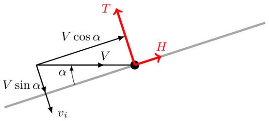
Figure 1.
Components of the airflow incident on a rotor disc ([26], p. 56).
The in-plane horizontal force, H, (i.e., the force in the plane formed by T and V) is given by
where is the rotor horizontal force coefficient.
Note that in this paper, we assume that the in-plane moment caused by the air flow is insignificant. This is generally true for hinged blades, however most multirotors use unhinged blades.
Finally, the rotor torque, Q, about the axial direction is given by [25]
where is the rotor torque coefficient.
2.1. Thrust Coefficient
The thrust coefficient can be determined from momentum theory which was originally developed by Glauert [27] building on the earlier work of Froude on aircraft propellers. Ignoring the flapping term, the thrust coefficient is derived as ([26], p. 59) (also see [28], p. 98):
where is the disc solidity factor, a is the rotor blade lift slope, is the blade pitch angle, is the rotor advance ratio (also the lateral wind component), and is the rotor inflow ratio. For a rotor disc with b blades of constant chord, c, and radius R, the solidity factor is defined as ([28], p. 48). For tapering blades, the chord can defined as the chord at the radius ([28], pp. 49, 98). For blades with a linear twist, the equation is still valid if the pitch angle at radius is used ([28], p. 98), that is where is the blade pitch at the roots and is the twist.
The rotor inflow ratio is the ratio of the axial flow velocity of the air to the tip speed of the rotor blade. Here it is considered positive in the direction of induced velocity, which is opposite to the thrust force and is given by ([26], p. 56)
where V is the incident flow velocity, is the induced velocity and is the angle between the incident flow and the tip-path plane as shown in Figure 1.
The rotor advance ratio is the ratio of the relative air velocity in the plane of the rotor and co-linear with the horizontal force to the tip speed of the rotor blade. It is considered positive in the direction of the horizontal force unlike the convention for the in-flow ratio and, ignoring the horizontal component of the induced velocity, is given by ([26], p. 56)
In this study, it is assumed that takes a maximum value of ([28], p. 96).
If it is assumed that the induced velocity is constant over the whole disc, the induced velocity can be calculated using the expression ([26], p. 52)
where is the induced velocity with the rotor in hover at the same thrust and is given by
2.2. In-Plane Force Coefficient
Along with vertical thrust, the rotor disk also has an in-plane horizontal force when the incident flow has a lateral component. This results mainly from the blade profile drag. The horizontal force coefficient is given by (note that this equation is incorrectly given in [19]) ([29], p. 149)
where is the blade profile drag coefficient and is the backward flapping angle which can be calculated from ([26], p. 65, Equation (5.50))
2.3. Blade Torque Coefficient
If the blade profile drag is represented as the polar
where is the angle of attack of the blade, then the torque coefficient can be determined by a detailed expression [30] that if is insignificant can be simplified to
2.4. Force and Moment Mappings
Multirotor vehicles are controlled by varying the rotor speed, of each rotor. To design the controller and analyze the dynamics, the mappings from to the triple are required. However, the triple also depend upon the airspeed magnitude, V, and incidence angle, . Hence the mappings from the triple , onto must be calculated.
The mappings are described by Equations (1)–(12). However, the presence of T in (8) means the equations are implicit and it appears that there is no tractable explicit solution. Calculation of the mapping thus requires a numerical method. In this paper, the MATLAB [31] routine, fzero, is used. The algorithm is based on the Brent-Dekker algorithm [32] and uses a combination of bisection, secant, and inverse quadratic interpolation methods [33,34] and includes an extension to check for sign changes. Other nonlinear function root-finding methods could be used.
In this paper, we provide an example that uses the rotors for the Draganflyer X-Pro quadrotor shown in Figure 2. The aircraft has undergone extensive wind tunnel and other experimental testing [23] from which we obtain the relevant parameters, , , m, m, , and rad.
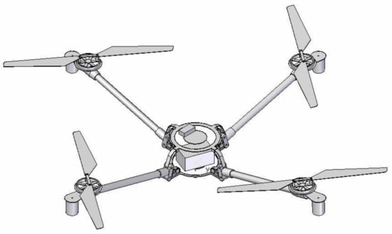
Figure 2.
Depiction of the Draganflyer X-Pro quadrotor [23].
The mapping for for constant airspeed values ms−1 is shown in Figure 3. Similarly, the mapping for for constant airspeed values ms−1 is shown in Figure 4, and the mapping for for constant airspeed values ms−1 is shown in Figure 5. The variation of thrust with airspeed is shown by the mapping for constant rotor speed rad s−1 and is shown in Figure 6.
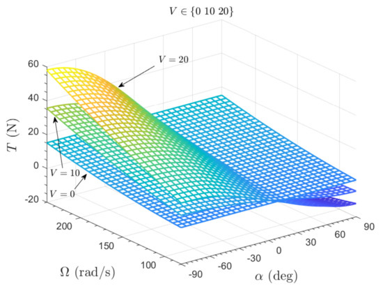
Figure 3.
Thrust force mapping for constant airspeeds, ms−1.
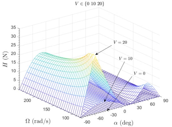
Figure 4.
Horizontal force mapping for constant airspeeds, ms−1.
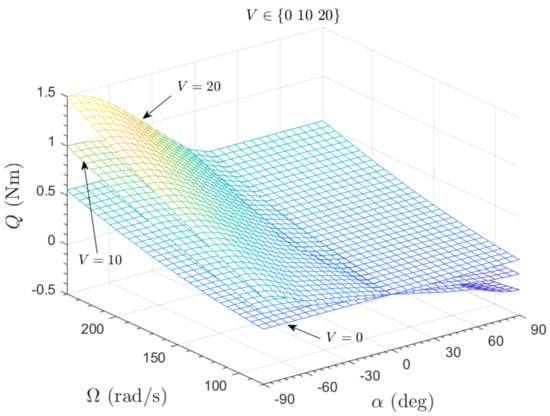
Figure 5.
Rotor torque mapping for constant airspeeds, ms−1.
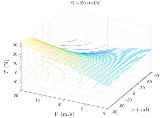
Figure 6.
Variation of thrust with airspeed for constant rotor speed, rad s−1.
3. PVTOL Equations of Motion
In order to understand how rotor tilt affects the gust rejection properties of multirotors, the dynamics of a 2-rotor PVTOL vehicle are modelled, the rotor aerodynamics models from Section 2 are included. The aircraft is a conceptual vehicle that is constrained to operate in the vertical -plane as shown in Figure 7. The rotors are symmetrically tilted outwards with an angle . The weight of the vehicle is W, x and z are the horizontal and vertical positions of the centre of gravity of the vehicle, is the pitch angle, u and w are the horizontal and vertical velocity components in the body axes, q is the pitch rate, is the wind which is assumed to be horizontal, , and , are the thrusts and drags, respectively, of the left and right rotors.
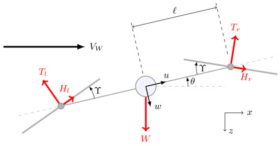
Figure 7.
Schematic of the PVTOL vehicle including rotor tilt, .
The equations of motion in the body axes are
where denotes , denotes , I is the moment of inertia, m is the vehicle mass, ℓ is the arm-length, and where g is the gravitational acceleration constant. We also have the navigation equations that relate the rates to the aircraft position in the airspace:
Vehicle Trim
The aircraft steady state (trim) conditions are determined next. This is a prerequisite for performing linear analysis of the aircraft dynamics. The aircraft is trimmed at hover in the earth coordinates with a steady horizontal wind. The trimmed variables are the pitch angle and the left and right rotor speeds denoted by , and , respectively. Setting the position and pitch rates and accelerations to zero in (13)–(22) gives
Note that and are dependent upon the rotor speed, , but the implicit nature of the thrust mapping means a numerical method is required to solve (23)–(25). The approach used here is to minimize the sum-of-squares residual of (23)–(25) using the MATLAB routine, fminsearch, which applies the Nelder-Mead simplex search method [35,36]. Note that other methods could be used. Additionally, note that for the still air condition () the solution is trivial and is given by and .
The PVTOL geometry is based on the Draganflyer X-Pro quadrotor, and is defined as kg m2, kg, m and [23]. The resulting trim maps for ms−1 are shown in Figure 8. Note that for , from (25) and hence . In particular, it can be seen that for low horizontal wind speeds (below about 15 ms−1), the trim rotor speed is below the hover value. This may seem counter-intuitive, but is caused by the lift that the wind provides combined with the fact that the vehicle drag is ignored, which would cause energy loss in a real vehicle.
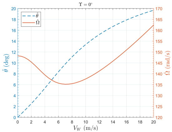
Figure 8.
Pitch and rotor speed trim maps for the PVTOL with .
Figure 9 shows the trim map for . The difference between the mean trim rotor rotation rate, , and the trim rotor rotation rate for is just 1 rad s−1 for hover in still air, is about 5 rad s−1 at and is much more significant at high wind speeds, with about a 17 rad s−1 difference at ms−1. This means that performance degradation resulting from the rotor tilt is increased at higher wind incident speeds. Figure 10 shows the dependence of the mean trim rotor speed on the tilt angle.
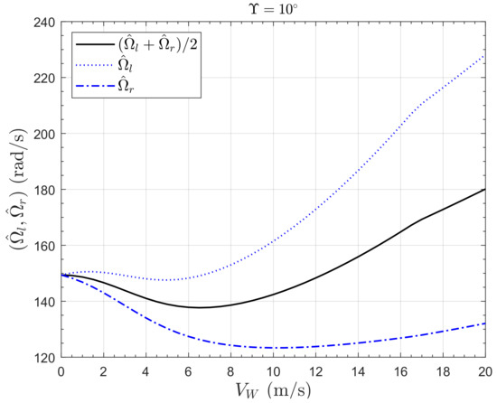
Figure 9.
Rotor speeds trim map for the PVTOL with .
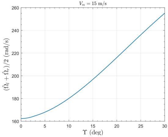
Figure 10.
Dependence of mean rotor speed trim on for the PVTOL at constant ms−1.
4. PVTOL Linear Dynamics
4.1. Model without Rotor Aerodynamics
The effect of the rotor tilt angle, on a linearized model of the dynamics in still air, that is , is analyzed first. In addition, the aerodynamics of the rotor are ignored, so the control is effected purely by the thrusts, , with the horizontal components, , assumed to be zero. From (13)–(15) and (20)–(22), the state vector is defined as and the control vector is defined as .
Assuming small perturbations about hover trim, the linear model is given by where
For the output , the system Laplace transfer function matrix is given by
The lateral position channel has a pair of zeros, . Provided is small, the zeros are high frequency and hence have little impact on the closed loop system performance. If , then there is a nonminimum phase zero. Note that and hence the open-loop stability is independent of . However is dependent on , and some direct control of the lateral position rate is achieved for , but this is adverse for , resulting in the nonminimum phase zero.
4.2. Model with Rotor Aerodynamics
The linearized model is extended to include the aerodynamic effects. The control is taken as
and the aerodynamic forces, , , are dependent upon the state, , control, and wind disturbance .
The dynamic equations, (13)–(22), are linearized at a set of trim points using the second order finite difference method ([37], p. 200). This gives the small perturbation model
where is the external disturbance.
The resulting state matrix is
where , and are the concise aerodynamic damping derivatives, and are concise cross-coupling aerodynamic derivatives. The remaining aerodynamic derivatives are all nearly zero.
Figure 11 shows the variation of the derivatives with . Note that for , the cross-coupling derivatives and are both zero and the resulting eigenvalues are , as expected from (30).
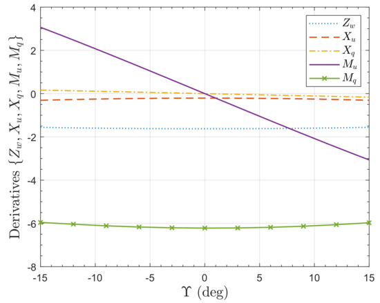
Figure 11.
Variation of aerodynamic derivatives, , for the PVTOL with for .
The dependence on of the real and imaginary parts of the eigenvalues is shown in Figure 12 and Figure 13, respectively. Note the high eigenvalue sensitivity when is near zero. Using the Routh-Hurwitz criterion, stability conditions can be determined. The system characteristic equation, , is
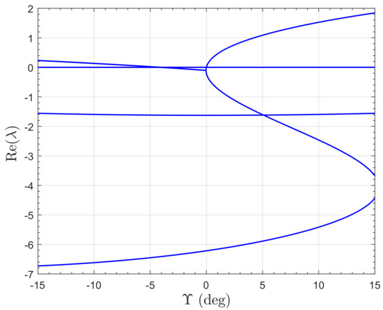
Figure 12.
Variation of real parts of eigenvalues of small perturbation model of the PVTOL for .
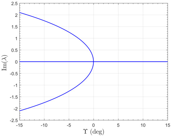
Figure 13.
Variation of imaginary parts of eigenvalues of small perturbation model of the PVTOL for .
For , the final term in (31), , is negative hence instability. For the system is also unstable, which can be shown to occur for
The control input matrix is
where , and are concise aerodynamic control derivatives. The remaining derivatives are all nearly zero. The variation of the control derivatives, , with is shown in Figure 14. Derivatives and are fairly constant, but changes sign to negative for .
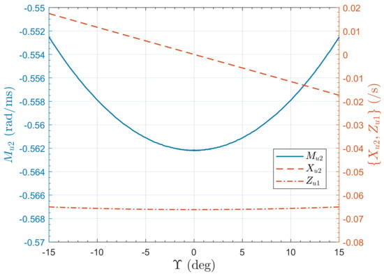
Figure 14.
Variation of control derivatives for the PVTOL with for .
Taking as the output, the system Laplace transfer function matrix is given by
Hence there is a zero pair in the horizontal position channel, , and a zero in the pitch channel, . For , the zeros of are left half plane and complex. The real part is fairly constant, approximately , and the imaginary parts approach infinity as approaches zero. For , the zeros are real, with one in each half plane. As increases, the zeros move from towards each other, and at the zero pair is at . The zero in is located at and it does not vary much and has a value of about .
Inspection of the disturbance input matrix, , shows the sensitivity of the pitch rotation rate to the wind disturbance, , where
Figure 15 shows the variation of the disturbance derivatives, with . Derivative is zero, is always positive as expected, and increases with increasing tilt angle magnitude. The moment derivative, is proportional to , being zero at . We see that although causes instability, it also provides a pitch down moment to the vehicle that will cause it to tilt into the wind when subjected to a lateral gust. This is potentially very beneficial for gust rejection. This property is explored next.
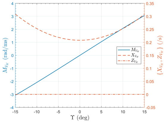
Figure 15.
Variation of disturbance derivatives for the PVTOL with for .
5. PVTOL Linear Control
In this Section, the dependence of the gust rejection properties of a PVTOL aircraft on the tilt angle, , is assessed. A set of four stabilizing controllers are designed. State feedback is assumed. The linearized model for hover trim in still air given by (29), (30) and (33) is used as the nominal model. Good control of multirotors for non-aggressive manoeuvres is easily obtained using standard Linear Quadratic Regulator (LQR) control (for example [38,39]). This was the approach used in [19], but it was difficult to compare the controllers for the different values of , so a different approach is used here. Because the vertical position channel and the horizontal position/pitch channel are very decoupled, the controllers for each channel can be designed independently as two SISO problems. We use pole-placement in order to obtain a consistent closed-loop performance for station-keeping in still air. The resulting gust-rejection properties can then be fairly compared.
The closed-loop pole locations are set to be close to the closed-loop pole locations for the LQR controller for from [19]. The closed-loop pole locations are for the vertical position channel and for the horizontal position/pitch channel. Simulation of the nonlinear plant model (13)–(22) with the controllers results in a consistent response to a horizontal position step demand. The lateral position, x, and pitch angle, , responses to a lateral position step demand of 10 m are presented in Figure 16 and Figure 17, respectively. The responses are nearly identical; the poles have been set so the position keeping is not too aggressive, so with a maximum pitch angle of about , the system dynamics remain fairly linear. The responses remain close until the step demand exceeds around 25 m. Note that there is a small amount of initial undershoot in the step response of x for resulting from the non-minimum phase, but it is barely perceptible in Figure 16. The vertical interaction is small, as shown in Figure 18, where small differences can be seen in the responses for the different values of tilt angle, . The rotor rotation rates are shown in Figure 19. It can be seen that the rotors have to work the hardest for and the least for , which is expected.
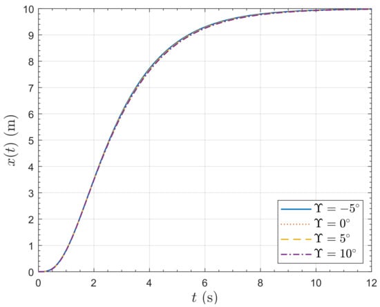
Figure 16.
Lateral position response of the PVTOL to a 10 m horizontal position step demand.
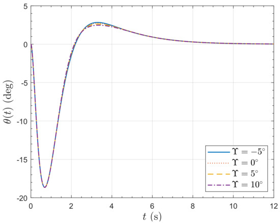
Figure 17.
Pitch angle response of the PVTOL to a 10 m horizontal position step demand.
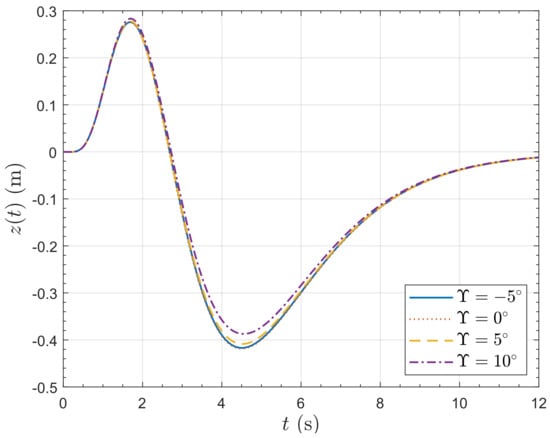
Figure 18.
Vertical position response of the PVTOL to a 10 m horizontal position step demand.
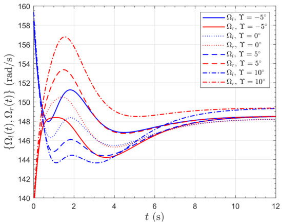
Figure 19.
Rotor speed response of the PVTOL to a 10 m horizontal position step demand.
Responses of the horizontal position to a lateral wind velocity step of 5 ms−1 are presented in Figure 20 and Figure 21. Video visualizations of the responses are available [24]. The gust rejection properties of the vehicle with are remarkable. For , the vehicle actually pitches into the wind, so much so that the final lateral position is negative, meaning that the vehicle actually moves up-wind. For , the vehicle almost exactly maintains horizontal position by pitching into the wind. Note that the controller does not contain integral action, so it does not compensate for the steady state position error. For , the vehicle pitches away from the wind, so that the effect of the gust on the lateral position is severe, resulting in a 12 m displacement. Figure 22 shows the resulting vertical position response; for all angles of , the vehicle finally gains an altitude of nearly 1 m. All the responses initially gain altitude because of the additional lift provided by the wind. The response then actually loses some altitude because the vehicle has pitched over and so loses enough vertical component of the rotor thrust to drop below the initial altitude; however this loss is recovered later. Figure 23 shows the rotor speed responses. As expected, the case rotors have to work the most to stabilize the vehicle because of the greatest pitch angle. The rotors have to work harder than the case because the negative pitch has to be recovered.
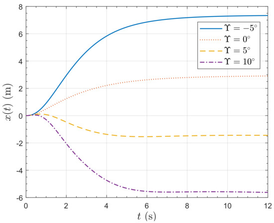
Figure 20.
Lateral position response of the PVTOL to a 5 ms−1 horizontal wind speed step.
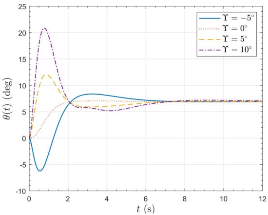
Figure 21.
Pitch angle response of the PVTOL to a 5 ms−1 horizontal wind speed step.
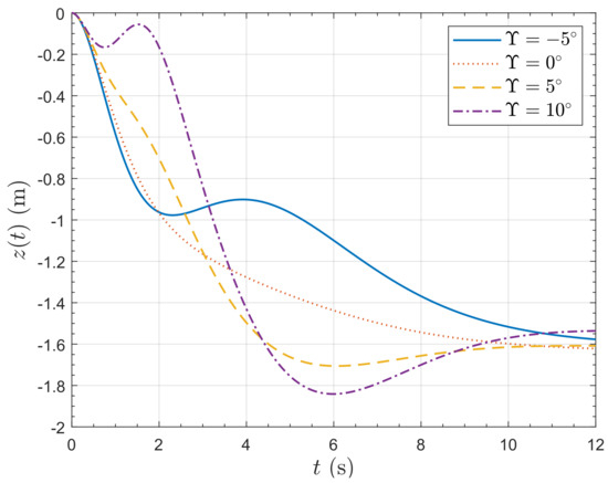
Figure 22.
Vertical position response of the PVTOL to a 5 ms−1 horizontal wind speed step.
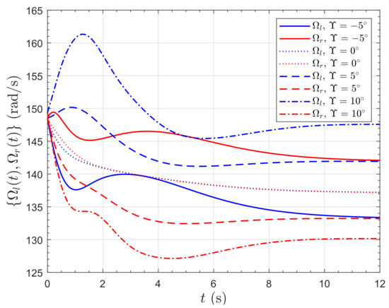
Figure 23.
Rotor speed response of the PVTOL to a 5 ms−1 horizontal wind speed step.
6. Quadrotor Gust Response
6.1. Equations of Motion
In this Section, the analysis is extended to assess the gust resilience of a quadrotor with fixed rotor tilt. The schematic of the quadrotor configuration is shown in Figure 24. The rotors are symmetrically tilted outwards with an angle . The earth reference frame is denoted by , the body-attached frame by and the four rotor frames by to . To model the vehicle dynamics, it is assumed that the structure is rigid and symmetric, the rotor Coriolis forces are insignificant, the motor dynamics bandwidth is high and can be ignored, and the centre of mass coincides with the origin of the body axes, .
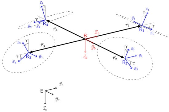
Figure 24.
Quadrotor vehicle schematic including outwards rotor tilt, .
The equations of motion are then the standard Newton–Euler equations
where is the total force vector acting on the center of mass in the body axes, m is the mass of the body, is the identity matrix, is the velocity vector of the center of mass, is the total moment vector acting about the center of mass, is the inertia matrix about and is the angular velocity vector of the body.
The body frame translational rates are related to the earth frame rates by where is the position of the centre of gravity in the earth frame, is the standard aerospace Euler angle (Tait-Bryan) triple and
is the Direction Cosine Matrix (DCM). Finally the Euler angle rates are related to the body angular velocities by
where denotes ,
The rotor aerodynamics are modelled as explained in Section 2. The thrust, horizontal disc force and torque triple, , for the i th rotor depend on air flow speed and incident angle on the rotor tip plane. Denoting the i th rotor axis unit vector by as shown in Figure 24 and the corresponding air flow vector by , the incident angle on the i th rotor tip plane, , is given by where is the air flow vector given by where is the wind vector and is the i th vehicle arm vector, that is the vector from to as shown in Figure 24. The resulting force and moment vectors are respectfully given by
The resulting total force, is given by
where is the earth down axis unit vector shown in Figure 24, and the total moment vector, , is
6.2. Quadrotor Steady State Analysis
In the same manner as the birotor in Section 4.2, the model is linearized and obtained in the form of (29). However, to aid the analysis, here we consider a reduced order form considering just the dynamic Equation (36), with a state variable vector . This removes the kinematics from the analysis whilst leaving the aerodynamics.
The resulting state matrix for the reduced order model is
where , etc. The remaining derivatives are zero or very small and can be ignored. The model with a tilt angle is trimmed with an x-direction for a headwind of ms−1. For incident airspeeds above approximately 16.6 ms−1, the rotor advance ratio (see (6)) exceeds 0.5, and so the reverse flow region becomes significant and the aerodynamic model is less reliable ([28], p. 96). The pitch trim variation shows similar trends to Figure 9, so is not shown here. The variations of the aerodynamic derivatives of (42) are of more interest.
Figure 25 shows the variation of the aerodynamic derivatives, , , , , , with . The lateral y-direction force term, , is almost constant and negative, indicating stability and independence from the incident airspeed. The x-direction force term, , is equal to the for with an increasing magnitude with , resulting from the increasing incident angle required to maintain trim. The variation in results mostly from the variation in rotor speed, with a lower magnitude with lower rotor speed. There is no cross-coupling for . The z-direction force initially increases providing lift in moderate winds, but levels-off as the pitch increases. The z-direction force derivative increases linearly with wind speed, and pitch angle.
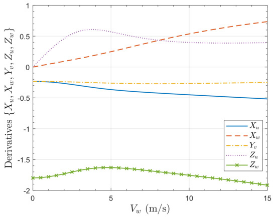
Figure 25.
Variation of aerodynamic derivatives, , for the quadrotor with for .
Figure 26 shows the variation of the aerodynamic force derivatives with respect to the rotation rates, , , , , with . The terms are small compared to shown in Figure 25. The terms all arise from the rotor tilt causing forces that are not parallel or orthogonal to the body axes.
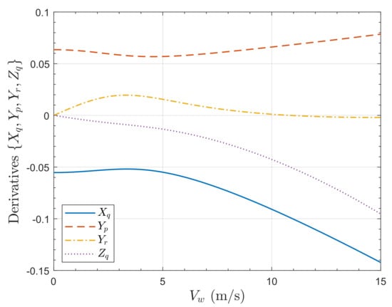
Figure 26.
Variation of aerodynamic derivatives, , for the quadrotor with for .
Figure 27 shows the variation of the aerodynamic moment derivatives, , , , , with . The pitch and roll rate damping derivatives, and , are equal and fairly constant with additional damping at high speed after an initial small reduction. The yaw rate damping derivative, , is, as expected, smaller than the roll and pitch derivatives and fairly constant. The cross-coupling terms are zero in still air. The roll moment derivative with respect to yaw rate shows the same trend as for . The magnitude of the term increases approximately linearly with , these terms arise from the rotor tilt.
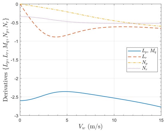
Figure 27.
Variation of aerodynamic derivatives, , for the quadrotor with for .
Figure 28 shows the variation of the aerodynamic moment derivatives with respect to the body velocities, , , , , with . These terms arise from the rotor tilt. The pitch moment derivative with respect to z-direction velocity increases in magnitude with the wind speed. The yaw moment derivative is small.
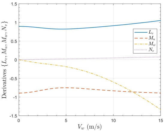
Figure 28.
Variation of aerodynamic derivatives, , for the quadrotor with for .
The plots show that rotor tilt introduces some dynamic cross-coupling. The effect on the closed-loop system is small as is seen in the next subsection.
6.3. Quadrotor Control
In order to investigate the gust rejection properties of the tilted rotors, LQR controllers are synthesized. The LQR control problem is well known. Given , a control input is determined such that closed loop system is stable with a gain that minimizes
where and are constant weighting matrices.
The objective is to control the positions, x, y, z, and yaw, , to maintain hover. Thus, the system output vector is set to and to ensure zero steady state errors, integral action in the controller is implemented by augmenting the linear model with the integral of the error, , where where is the reference input vector. Hence, given , then the augmented system is
with state feedback
where is partitioned as . The linearized control schematic is shown in Figure 29. Note that for a practical LQR controller, an additional nonlinear element should be included in the LQR architecture to rotate the x and y errors by to align them with the body axes in the horizontal plane. That is not required in this study because is small for the simulations.

Figure 29.
Draganflyer X-Pro quadrotor LQR control schematic with integral action.
Linearized models for hover trim in still air are used to obtain the model, and the weighting matrices are set to and . Nonlinear system simulations are performed to evaluate the responses to a lateral position step demand for two values of tilt, and . Figure 30 shows the position responses to a 10 m step demand in x for the nonlinear model with tilt and outwards tilt. The responses are very similar, thus providing a fair means for evaluating the effect of the tilt. The resulting attitude responses are shown in Figure 31. Here the tilt pitch response is noticeably greater than the tilt response. This is because when the aircraft pitches to move forward, the front rotor () has an additional tilt, and this rotor is exploited by the controller to give additional force in the x-direction but requiring less pitch.
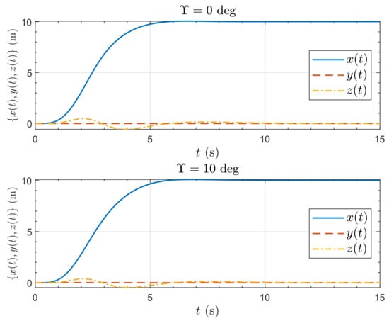
Figure 30.
Position response of the Draganflyer X-Pro quadrotor to a 10 m x-position step demand.
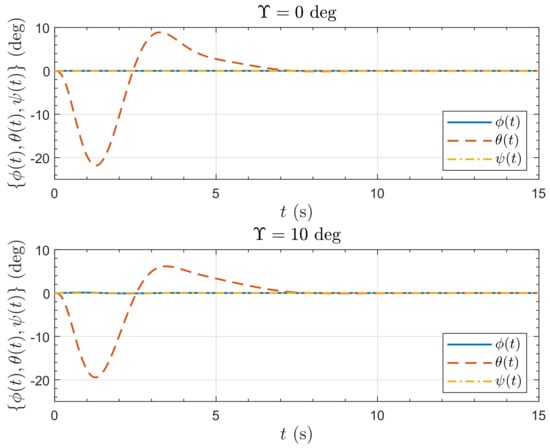
Figure 31.
Attitude response of the Draganflyer X-Pro quadrotor to a 10 m x-position step demand.
Figure 32 and Figure 33 show, respectively, the position and attitude responses to a 10 ms−1 gust step in the x-direction. Both position responses show an initial lateral displacement downwind. For the untilted case (), the controller responds by pitching the aircraft into the wind until the x-position is recovered and settles with a trimmed pitch of . The maximum displacement is about 1.4 m and the maximum pitch is occurring at 1.35 s. For the tilted case (), the gust causes the aircraft to pitch down into the wind which, after a short downwind displacement, causes an upwind displacement. The controller responds by reducing the pitch so that the x-position is recovered, settling with a trimmed pitch of just under . The maximum downwind displacement is about 0.3 m and the maximum upwind displacement is just under 0.8 m. The maximum pitch is about greater than the untilted case, and occurs far earlier after just 0.73 s. This demonstrates the ability of the tilted configuration to withstand wind gusts.
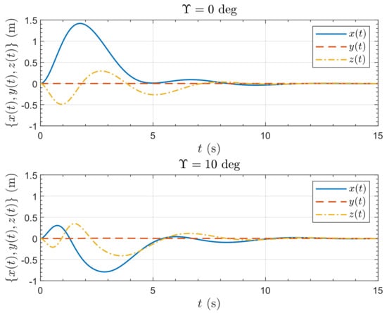
Figure 32.
Position response of the Draganflyer X-Pro quadrotor to a 10 ms−1 wind gust step in x-direction.
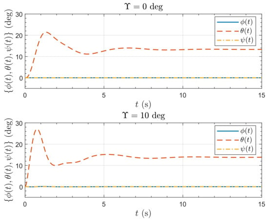
Figure 33.
Attitude response of the Draganflyer X-Pro quadrotor to a 10 ms−1 wind gust step in x-direction.
Note that both configurations result in an initial altitude gain due to the additional lift from the lateral wind as seen in Figure 8. With close observation it can be seen that there is a small amount of cross-coupling to the y-direction and the yaw, . It is slightly greater for the tilted configuration resulting from the rotor tilts meaning the force and moments vectors are not aligned with the body axes. However, with a tilt of just , the amount is small.
7. Discussion and Conclusions
The problem of gust resilience for multirotor VTOL aircraft is considered. It is proposed that introducing an outward tilt to the rotors improves the gust rejection properties of the vehicle. The effect is analyzed on both a PVTOL aircraft and a quadrotor. The following conclusions can be drawn:
- The gust rejection properties of multirotor VTOL aircraft can be analyzed and simulated by modelling the aerodynamics of the rotors using standard methods. The methods are suitable for simulation studies that include the aircraft dynamics, but include a nonlinear implicit equation which must be solved numerically. This can be done rapidly using standard methods.
- Trim analysis for the PVTOL shows that for operation in moderate wind (or for cruise) additional lift is generated by the rotors.
- The effect of rotor tilt on the dynamics of the PVTOL is explored and analyzed. It is seen that an inwards tilt results in increased open-loop static stability, although dynamic stability can be lost for large tilt angles. However outward tilt results in a loss of static stability and some non-minimum phase. For small tilt angles, the non-minimum phase behaviour is high frequency and hence has little effect on the control performance, but the loss of static stability means that some ‘hunting’ may result at hover.
- Simulations of both the PVTOL and quadrotor show that the outwards tilt causes a pitch down moment when subjected to a lateral wind increase. This anticipates the necessary control action to recover the lateral position by aiming the vehicle thrust into the wind and so improves the gust rejection property beyond that provided by the feedback control.
It should be noted that, in essence, outwards tilt introduces anhedral into the aircraft. The gust disturbance rejection properties of anhedral in fixed-wing aircraft are fairly well-known, and is the reason why VTOL fixed-wing aircraft such as the Harrier have notable anhedral. The dynamics of such aircraft have been explored by Hauser, Sastry and Meyer [40]. It should also be noted that most commercial surveillance and observation quadrotor platforms have the camera located below the centre of gravity, which gives the vehicle some inherent gust resilience because the drag of the camera causes a pitch down into a wind gust. Detailed investigation into this could be the subject of further study.
Apart from loss of static stability, the introduction of fixed rotor tilt has another disadvantage. It is obvious that rotors with non-parallel rotor axes will be less efficient and reduce the endurance of the vehicles in still air. This is not investigated in detail in this paper, and the trade-off between reduced efficiency and improved gust resilience is a matter for further study.
The pitching into the wind that results from outwards rotor tilt could also be achieved by aerodynamic ‘tailoring’ of the vehicle body shape, a detailed study of aerodynamic design trade-off remains for future work. Finally, validation of the effect of outward tilt requires experimental validation, both by wind tunnel test to add to that of Otsuka, Sasaki and Nagatani [22] and by flight test.
Author Contributions
Concept, J.F.W.; development, J.F.W., A.P.M. and A.C.; simulations and analysis, J.F.W. and A.P.M.; writing—original draft preparation, J.F.W.; writing—review and editing, J.F.W., A.P.M. and A.C. All authors have read and agreed to the published version of the manuscript.
Funding
This research received no external funding.
Data Availability Statement
The MATLAB software that generates the data and a video visualization are available in the Cranfield Online Research Data (CORD) repository, [24].
Conflicts of Interest
The authors declare no conflict of interest.
References
- Alexis, K.; Nikolakopoulos, G.; Tzes, A. Model predictive quadrotor control: Attitude, altitude and position experimental studies. IET Control Theory Appl. 2012, 6, 1812–1827. [Google Scholar] [CrossRef]
- Araar, O.; Aouf, N. Quadrotor control for trajectory tracking in presence of wind disturbances. In Proceedings of the 2014 UKACC International Conference on Control, CONTROL 2014, Loughborough, UK, 9–11 July 2014; pp. 25–30. [Google Scholar] [CrossRef]
- Kun, D.W.; Hwang, I. Linear matrix inequality-based nonlinear adaptive robust control of quadrotor. J. Guid. Control. Dyn. 2016, 39, 996–1008. [Google Scholar] [CrossRef]
- Raza, S.A.; Etele, J. Autonomous position control analysis of quadrotor flight in urban wind gust conditions. In Proceedings of the 2016 AIAA Guidance, Navigation, and Control Conference, Chicago, IL, USA, 16–19 August 2016. [Google Scholar] [CrossRef]
- Dean, W.A.; Ranganathan, B.N.; Penskiy, I.; Bergbreiter, S.; Humbert, J.S. Robust gust rejection on a micro-air vehicle using bio-inspired sensing. In Mechatronics and Robotics Engineering for Advanced and Intelligent Manufacturing; Zhang, D., Wei, B., Eds.; Lecture Notes in Mechanical Engineering; Springer: Cham, Switzerland, 2017. [Google Scholar] [CrossRef]
- Demircioglu, H.; Basturk, H.I. Adaptive attitude and altitude control of a quadrotor despite unknown wind disturbances. In Proceedings of the 56th Annual Conference on Decision and Control (CDC 2017), Melbourne, Australia, 12–15 December 2017; pp. 274–279. [Google Scholar] [CrossRef]
- Yang, H.; Cheng, L.; Xia, Y.; Yuan, Y. Active disturbance rejection attitude control for a dual closed-loop quadrotor under gust wind. IEEE Trans. Control Syst. Technol. 2018, 26, 1400–1405. [Google Scholar] [CrossRef]
- Rodríguez-Mata, A.E.; González-Hernández, I.; Rangel-Peraza, J.G.; Salazar, S.; Leal, R.L. Wind-gust compensation algorithm based on high-gain residual observer to control a quadrotor aircraft: Real-time verification task at fixed point. Int. J. Control. Autom. Syst. 2018, 16, 856–866. [Google Scholar] [CrossRef]
- Craig, W.; Yeo, D.; Paley, D. Geometric attitude and position control of a quadrotor in wind. J. Guid. Control. Dyn. 2020, 43, 870–883. [Google Scholar] [CrossRef]
- Pounds, P.; Mahoney, R.; Gresham, J.; Corke, P.; Roberts, J. Towards Dynamically Favourable Quad-Rotor Aerial Robots. In Proceedings of the Australasian Conference on Robotics and Automation, Canberra, Australia, 6–8 December 2004. [Google Scholar]
- Bangura, M.; Mahony, R. Nonlinear Dynamic Modeling for High Performance Control of a Quadrotor. In Proceedings of the Australasian Conference on Robotics and Automation, Wellington, New Zealand, 3–5 December 2012. [Google Scholar]
- Waslander, S.; Wang, C. Wind disturbance estimation and rejection for quadrotor position control. In Proceedings of the AIAA Infotech@Aerospace Conferences, Seattle, WA, USA, 6–9 April 2009. Number AIAA 2009-1983. [Google Scholar] [CrossRef]
- Bristeau, P.J.; Martin, P.; Salaün, E.; Petit, N. The role of propeller aerodynamics in the model of a quadrotor UAV. In Proceedings of the 2009 European Control Conference (ECC), Budapest, Hungary, 23–26 August 2009; pp. 683–688. [Google Scholar] [CrossRef]
- Naidoo, Y.; Stopforth, R.; Bright, G. Rotor Aerodynamic Analysis of a Quadrotor for Thrust Critical Applications. In Proceedings of the 4th Robotics and Mechatronics Conference of South Africa (ROBMECH 2011), Gauteng, South Africa, 23–25 November 2011. [Google Scholar]
- Sydney, N.; Smyth, B.; Paley, D.A. Dynamic control of autonomous quadrotor flight in an estimated wind field. In Proceedings of the 52nd IEEE Conference on Decision and Control (CDC), Firenze, Italy, 10–13 December 2013; pp. 3609–3616. [Google Scholar] [CrossRef]
- Kai, J.M.; Allibert, G.; Hua, M.D.; Hamel, T. Nonlinear feedback control of quadrotors exploiting first-order drag effects. IFAC-PapersOnLine 2017, 50, 8189–8195. [Google Scholar] [CrossRef]
- Del Cont Bernard, D.; Riccardi, F.; Giurato, M.; Lovera, M. A dynamic analysis of ground effect for a quadrotor platform. IFAC-PapersOnLine 2017, 50, 10311–10316. [Google Scholar] [CrossRef]
- Lopez, M.; Tischler, M.; Juhasz, O.; Gong, A.; Sanders, F.; Soong, J.; Nadell, S. Flight test comparison of gust rejection capability for various multirotor configurations. In Proceedings of the Vertical Flight Society–Forum 75: The Future of Vertical Flight, Philadelphia, PA, USA, 13–16 May 2019. [Google Scholar]
- Whidborne, J.F.; Cooke, A.K. Gust rejection properties of VTOL multirotor aircraft. IFAC-PapersOnLine 2017, 50, 175–180. [Google Scholar] [CrossRef]
- Fantoni, I.; Palomino, A. Nested Saturation Control for Stabilizing the PVTOL Aircraft. In Unmanned Aerial Vehicles; John Wiley: Hoboken, NJ, USA, 2013; Chapter 2; pp. 21–40. [Google Scholar] [CrossRef]
- Otsuka, H.; Nagatani, K. Reduction of pitching moment generation of a quadrotor UAV in gust with slant rotors. In Proceedings of the AIAA SciTech Forum—55th AIAA Aerospace Sciences Meeting, Grapevine, TX, USA, 9–13 January 2017. [Google Scholar] [CrossRef]
- Otsuka, H.; Sasaki, D.; Nagatani, K. Reduction of the head-up pitching moment of small quad-rotor unmanned aerial vehicles in uniform flow. Int. J. Micro Air Veh. 2018, 10, 85–105. [Google Scholar] [CrossRef]
- Martínez, V.M. Modelling of the Flight Dynamics of a Quadrotor Helicopter. Master’s Thesis, Cranfield University, Bedfordshire, UK, 2007. [Google Scholar]
- Whidborne, J.F. The Effect of Rotor Tilt on the Stability and Gust Rejection Properties of VTOL Multirotor Aircraft—MATLAB Codes. In Cranfield Online Research Data (CORD) Repository, Version 2; Cranfield University: Bedfordshire, UK, 2022. [Google Scholar] [CrossRef]
- Cooke, A.K.; Fitzpatrick, E.W.H. Helicopter Test and Evaluation; Blackwell Science: Oxford, UK, 2002. [Google Scholar]
- Seddon, J. Basic Helicopter Aerodynamics; BSP Professional: Oxford, UK, 1990. [Google Scholar]
- Glauert, H. The Elements of Aerofoil and Airscrew Theory; Cambridge University Press: Cambridge, UK, 1983. [Google Scholar]
- Bramwell, A.R.S.; Done, G.; Balmford, D. Bramwell’s Helicopter Dynamics, 2nd ed.; Butterworth-Heinemann: Oxford, UK, 2001. [Google Scholar]
- Bramwell, A.R.S. Helicopter Dynamics; Edward Arnold: London, UK, 1976. [Google Scholar]
- Prouty, R.W. Helicopter Performance, Stability, and Control; Krieger: Malabar, FL, USA, 1990. [Google Scholar]
- Mathworks. MATLAB Version 9.6.0.1174912 (R2019a); The Mathworks, Inc.: Natick, MA, USA, 2019. [Google Scholar]
- Brent, R.P. An algorithm with guaranteed convergence for finding a zero of a function. Comput. J. 1971, 14, 422–425. [Google Scholar] [CrossRef]
- Forsythe, G.E.; Malcolm, M.A.; Moler, C.B. Computer Methods for Mathematical Computations; Prentice Hall: Englewood Cliffs, NJ, USA, 1977. [Google Scholar]
- Moler, C.M. Numerical Computing with Matlab; SIAM: Philadelphia, PA, USA, 2004. [Google Scholar] [CrossRef]
- Nelder, J.A.; Mead, R. A simplex method for function minimization. Comput. J. 1965, 7, 308–313. [Google Scholar] [CrossRef]
- Lagarias, J.C.; Reeds, J.A.; Wright, M.H.; Wright, P.E. Convergence Properties of the Nelder–Mead Simplex Method in Low Dimensions. SIAM J. Optim. 1998, 9, 112–147. [Google Scholar] [CrossRef]
- Stevens, B.L.; Lewis, F.L.; Johnson, E.N. Aircraft Control and Simulation: Dynamics, Controls Design, and Autonomous Systems, 3rd ed.; Wiley: Hoboken, NJ, USA, 2016. [Google Scholar]
- Cowling, I.D.; Whidborne, J.F.; Cooke, A.K. Optimal trajectory planning and LQR control for a quadrotor UAV. In Proceedings of the UKACC International Conference Control 2006 (ICC2006), Glasgow, UK, 11–15 June 2006. p. CD ROM paper 125. [Google Scholar]
- Cowling, I.D.; Yakimenko, O.A.; Whidborne, J.F.; Cooke, A.K. Direct method based control system for an autonomous quadrotor. J. Intell. Robot. Syst. 2010, 60, 285–316. [Google Scholar] [CrossRef]
- Hauser, J.; Sastry, S.; Meyer, G. Nonlinear control design for slightly non-minimum phase systems: Application to V/STOL aircraft. Automatica 1992, 28, 665–679. [Google Scholar] [CrossRef]
Publisher’s Note: MDPI stays neutral with regard to jurisdictional claims in published maps and institutional affiliations. |
© 2022 by the authors. Licensee MDPI, Basel, Switzerland. This article is an open access article distributed under the terms and conditions of the Creative Commons Attribution (CC BY) license (https://creativecommons.org/licenses/by/4.0/).