Article

SORA Methodology for Multi-UAS Airframe Inspections in an Airport

by
Carol Martinez
1,*,
Pedro J. Sanchez-Cuevas
1,
Simos Gerasimou
2,
Abhishek Bera
1 and
Miguel A. Olivares-Mendez
1
1
Space Robotics Research Group (SpaceR), SnT Interdisciplinary Centre for Security, Reliability and Trust, University of Luxembourg, 4365 Esch-sur-Alzette, Luxembourg
2
Department of Computer Science, University of York, Haslington, York YO10 5DD, UK
*
Author to whom correspondence should be addressed.
Drones 2021, 5(4), 141; https://doi.org/10.3390/drones5040141
Submission received: 11 October 2021 / Revised: 15 November 2021 / Accepted: 17 November 2021 / Published: 24 November 2021

Abstract

:
Deploying Unmanned Aircraft Systems (UAS) in safety- and business-critical operations requires demonstrating compliance with applicable regulations and a comprehensive understanding of the residual risk associated with the UAS operation. To support these activities and enable the safe deployment of UAS into civil airspace, the European Union Aviation Safety Agency (EASA) has established a UAS regulatory framework that mandates the execution of safety risk assessment for UAS operations in order to gain authorization to carry out certain types of operations. Driven by this framework, the Joint Authorities for Rulemaking on Unmanned Systems (JARUS) released the Specific Operation Risk Assessment (SORA) methodology that guides the systematic risk assessment for UAS operations. However, existing work on SORA and its applications focuses mainly on single UAS operations, offering limited support for assuring operations conducted with multiple UAS and with autonomous features. Therefore, the work presented in this paper analyzes the application of SORA for a Multi-UAS airframe inspection (AFI) operation, that involves deploying multiple UAS with autonomous features inside an airport. We present the decision-making process of each SORA step and its application to a multiple UAS scenario. The results shows that the procedures and safety features included in the Multi-AFI operation such as workspace segmentation, the independent multi-UAS AFI crew proposed, and the mitigation actions provide confidence that the operation can be conducted safely and can receive a positive evaluation from the competent authorities. We also present our key findings from the application of SORA and discuss how it can be extended to better support multi-UAS operations.

1. Introduction

The European strategy and research roadmaps emphasize the increasing use of Unmanned Aircraft Systems (UAS) in safety-critical applications, including realtime road traffic monitoring and UAS-driven aerial inspection activities [1]. The ongoing demand for UAS-assisted operations attracts the involvement of multiple UAS to expedite the mission, such as inspection [2], collaborative localization and mapping [3,4], disaster management [5,6], and search and rescue [7,8]. However, involving multiple UAS incurs risks and challenges, and a detailed analysis to estimate the associated risks of such missions is mandatory.
According to the new EASA regulation, UAS operations can fall under three specific categories: open (low risk), specific (medium risk), and certified (high risk) [9]. Operations considered under the open category do not require authorization by the National Aviation Authority (NAA). Operations within the specific category require the submission of a risk assessment to the NAA for approval. Finally, operations characterized as certified require more rigorous assurance processes as well as certification of the aircraft, the operator, and the licensing of remote pilots. To facilitate the authorization process, the Joint Authorities for the Rulemaking of Unmanned Systems (JARUS) developed the Specific Operation Risk Assessment (SORA) methodology, which has been endorsed by the EASA as an Acceptable Means of Compliance (AMC) to fulfil the requirements of the EU Regulations [10] (the latest version is SORA V2.0). SORA is a guideline to define and evaluate the risks involved in UAS operations. It is a promising step towards a harmonized regulatory framework for assured UAS operations that can also be used by local authorities to create standard scenarios with clear rules and mitigation measures that fit their regulatory framework.
This paper discusses the application of the SORA methodology to reduce the associated risks of a Multiple UAS AirFrame Inspection operation (Multi-UAS AFI) of Cargolux airplanes at Luxembourg Airport, which is a non-contractual partner of the SAFEMUV project (Safe Airframe Inspection using Multiple UAVs) [11]. UAS-based inspections are strategically significant in reducing the expensive and time-consuming manual inspection process. As confirmed by the inspection team of Cargolux, an effective inspection process is necessary both to ensure that the aircraft is in a safe operational condition and to reduce the aircraft inspection time. Furthermore, the employment of UAS has significant benefits both for scheduled and unscheduled visual airframe inspections, such as automated damage inspection, reduction in time for aircraft on the ground, and reduction in effort and cost to send human inspectors for unscheduled inspections, among other benefits.
Recently, the SORA methodology has been analyzed and discussed in different applications, such as for UAS-based cinematography [12] and UAS-based maritime surveillance mission [13], and a web-based tool has been developed to to support its application [14]. However, the SORA framework is very new and abstract with limited guidance on how regulatory bodies and operators should use it. Furthermore, the current format of the framework captures exclusively UAS falling under the specific category, whose operations are primarily remotely piloted and with low levels of autonomy [15]. As such, there is limited information on how SORA can provide assurance to operations, such as the one described in this paper, in which UASs (1) undertake tasks in restricted airspaces; (2) exhibit autonomous behavior; or (3) form teams to operate collaboratively to perform the inspection more efficiently. Therefore, providing assurance for autonomous multi-UAS-driven missions remains a very challenging task.
Because of this, the main contribution of this paper is to provide guidelines on applying SORA V2.0 in a Multi-UAS scenario that includes the use of autonomous behaviors in a restricted airspace. This work also discusses possible extension/modifications of SORA required for covering the Multi-UAS AFI scenario, proposing to reduce the operational risk of the operation, as follows:
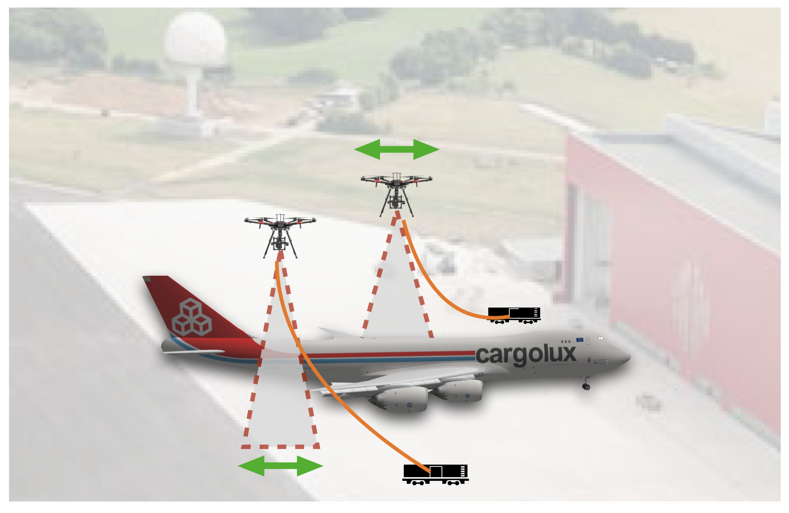
  • Primarily, SORA mentioned three types of risks during a UAS-assisted mission, (A) injuries to third parties on the ground, (B) injuries to third parties in the air, and (C) damage to critical infrastructure [15]. To deal with the aforementioned risks, we adopted three safety measures during the airframe inspection. First, we created a restricted operational area so that any non-participant could not enter. This approach substantially reduces the risk associated with type A. In addition to this, we also created a restricted operational area for each UAS, a tethered system, and a shared information system to share the UAS location to avoid inter-UAS collisions. As a result, the risk associated with type B is reduced. Finally, we created a no-fly zone around the airframe to avoid collisions, thus mitigating type C risks.
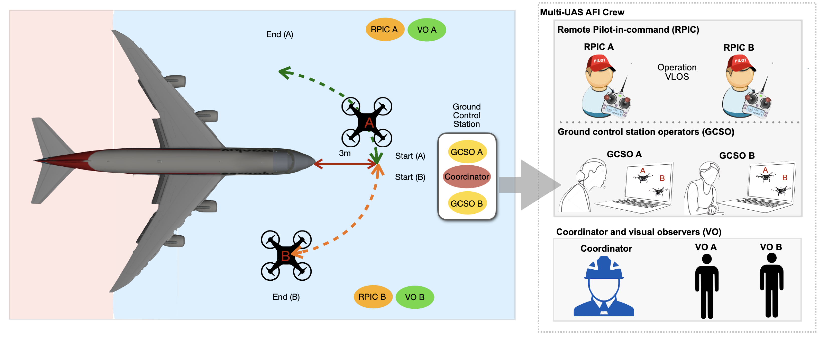
  • Multi-UAS AFI operation introduces a three layer crew architecture in order to conduct a successful mission, (a) Remote Pilot-in-Command (RPIC), (b) Ground Control Station Operator (GCSO), and (c) coordinator and visual observer (VO) to enhance the mission and flight safety. VOs are in charge of detecting the aircraft using visual observations (conducting the “see” strategy). On the other hand, the RPIC or the GCSO is responsible for conducting the “avoid” strategy.
  • The proposed Multi-UAS AFI operation is conducted a using behavior-based approach. To switch among the different behaviors (takeoff, landing, free-motion, and inspect), the GCSO must select the desired behavior of the UAS using the ground control station (GCS) during the operation, i.e., we embedded a human in the loop to enhance the mission safety.
The paper is organized as follows. Section 2 presents related work, Section 3 presents a summary of the concept of operation (CONOPS) for the Multi-UAS AFI operation. Section 4 describes step by step the SORA methodology for the Multi-UAS AFI operation. Section 5, discusses the results of the SORA methodology. Finally, Section 6 presents the conclusions and direction of future work.

2. Related Work

2.1. SORA-Based Applications

The SORA methodology [10] assesses the risk of UAS operations. It helps National Aviation Authorities (NAA) to decide on whether a UAS mission should be authorized or not. According to the new EASA regulatory framework of UAS, operations that fall under the specific category must present to the NAA a risk assessment according to SORA. Because the framework is new, only a few cases are found in the state-of-the-art. Two SORA versions have been released so far: V1.0 [15] and the latest one V2.0 [10].
Capitan et al. [12] describe the application of SORA V1.0 for a multi-UAS cinematography operation for filming rowing and cycling events in rural areas. In the article, the authors walked through all the phases of the SORA methodology analyzing operational risks and highlighting mitigation actions. The analysis was focused on a single UAS scenario. The authors discuss that the SORA methodology should be extended to cover the risks associated with multi-UAS operations. However, the paper does not provide insights of how the changes should be addressed. Denney et al. [16] analyzed the risk identification challenges and inconsistencies of the existing SORA methodology V1.0. They introduced a Bayesian framework to enhance the barrier-based safety model to increase the robustness and assurance of SORA.
On the other hand, Miles et al. [13] discussed the SORA system for large Remotely Piloted Aircraft System (RPAS) on Australian airspace for open ocean environments. The authors analyzed the associated risks of a maritime surveillance mission. They prepared a CONOPS for flight plan and the associated stakeholders for the mission. As a conclusion, the authors identified a few improvement that can be included in SORA such as the various levels of safety inside controlled airspace, the possibility of lowering the Final Ground Risk Class (GRC), and analysis of “near-real-time” density data. Terkildsen et al. [14] developed a SORA-based evaluation tool for a UAS mission to mitigate the gap between the technical requirement of a UAS mission and the available UAS platform, based on SORA V2.0. In that work, the authors considered four UAV platforms, such as DJI Phantom 4 Pro, DJI Inspire 2, DJI Matrice 200, and DJI Matrice 600 Pro. They developed a web-based platform where a user provides answers to questions related to the UAS mission. As a result, the web-based platform generates a guideline that can be introduced into SORA for future use. However, the questionaries should be improved with the help of more UAS manufacturers. In one of the latest works, Janik et al. [17] analyzed the risks associated with first responder and disaster management operations. In the paper, they identified that the current version of SORA V2.0 does not cover the risk in applications involving multiple UAS, neither safety for rescue operations. As an extension of the current SORA methodology, they suggest incorporating new technologies such as cooperation between multiple UAS to reduce the associated risks and increase the safety of the operation.

2.2. UAV-Assisted Airframe Inspection

Airframe inspection is a very sensitive activity within the entire aircraft maintenance process. Currently, airframe inspection is carried out manually. The inspection process distinguishes between scheduled airframe inspections, conducted at regular intervals comprising various types of routine checks, and unscheduled airframe inspections taking place when the aircraft encounters unforeseen situations such as a lightning or bird strike. More than 80 % of all inspection activities are visual aiming to “detect obvious damage, failure or irregularity” [18], such as dents, scratches, cracks, and buckles. These activities are typically conducted by human inspectors and use a mobile or temporary platform around the aircraft [19]. The addition of an ultraviolet light and a wide field-of-view camera to an off-the-shelf UAV reduced airframe inspection time, cost, and human effort. Additionally, the realtime video feed to the ground-based controller, which executes the defects detection algorithm, increased the detection probability of potential hazards of the airframe [20]. In [21], the authors used a long-wave infrared camera mounted on the UAV to identify the structural and surface damage of a trainer aircraft airframe. In addition, the authors proposed a Radio Frequency Identification (RFID)-based inspection framework to identify the electronic failure caused by a faulty screw or rivet. On the other hand, for unscheduled inspections when an aircraft lands at a different location, airline operators may need to fly their inspectors to the inspection. These incidents are very expensive and increase the time that an aircraft is on the ground. Driven by the need to streamline the visual airframe inspection process, the Airframe Inspection (AFI) project [22] demonstrated the positive impact that UASs can have in executing (part of) the inspection autonomously. The UAS used high-resolution cameras to capture high-quality images of the airframe while maintaining a safe distance from the aircraft through specialized collision-free navigation and trajectory planning and execution systems. While single UAS-missions are limited in their sensing and energy abilities, both scheduled and unscheduled inspection tasks could be significantly improved by utilizing teams of UAS designed to operate collectively [23]. Through collective behavior, we could exploit not only the heterogeneity of the platforms (e.g., different sensing modalities) to decompose the overall mission effectively but also improve the overall system performance (e.g., by minimizing the total inspection time and cost) and reliability. Recently, Donecle [24] developed a vision-based autonomous UAV to inspect an aircraft. The UAV captures images of different parts of an aircraft and transfers them to a remote computer, which executes software to generate the inspection report for the aircraft. Generally, the image capturing process takes less than an hour for them. The proposed system can identify potential structural damage.

2.3. Synthesis

The existing literature describes the steps, limitations, and inconsistencies of the SORA methodology (V1.0 and V2.0) to identify the risks associated with a specific operation, and the challenges with respect to single or multi-UAS operations. Some of the existing work deals with multi-UAS operations [12]. However, the analysis is based on SORA V1.0 and assumes a single-UAS case. Therefore, none of the existing work attempted to analyze SORA when multiple UAS were involved in the mission, including operations with autonomous features, and in a highly sensitive area as an airport. In this article, we detailed the steps followed to apply SORA V2.0 for the Multi-UAS AFI scenario, we discuss the risks, identify the safety measures to comply with the new regulatory framework, and propose changes to SORA to ensure safety in Multi-UAS operations.

3. Multi-UAS Airframe Inspection

A CONOPS is the first step to conduct the risk assessment of an operation and is mandated by the National Aviation Authorities when applying for operation approval. A CONOPS was developed for the Multi-UAS AFI operation [25], under the framework of the SAFEMUV project (Safe Airframe Inspection using Multiple UAVs) [11]. In this section, we present the CONOPS information relevant to the SORA process.
The operation to be conducted in SAFEMUV was the visual inspection of Cargolux airplanes at Luxembourg Airport (in a controlled and very low level VLL airspace). The mission, as described in Figure 1, involved flying two multirotor UAS around the airframe, simultaneously acquiring high-quality images of its condition. During the flight, the UAS maintained a safe distance from the aircraft through specialized trajectory planning and execution systems, and never flew over the airframe. The UAS used a tethered system [26] that increased the endurance by reducing battery restrictions during the operation and acted as an anchor in case of emergency.
The UAS to be used for the operation corresponded to the Matrice 600 from DJI [27]. Table 1 describes the main components of the UAS [27]. The UAS included two different flight modes: (i) semi-autonomous mode in which autonomous behaviors were activated manually by the GCSO; and (ii) manual mode in which the control was passed to the RPIC. These modes were activated by the RPIC using the remote controller.
The Multi-AFI operation was conducted using a behavior-based approach, created specifically for the mission. To switch among the different behaviors (takeoff, landing, free motion, and inspect), the GCSO must select the desired behavior of the UAS using the GCS during the operation. Once selected, the UAS conducted the task autonomously, except for the free-motion behavior, which allowed the RPIC to provide relative motion commands to the UAS using the GCS. When the UAS was executing any of the previously mentioned behaviors, the operation could be interrupted by the RPIC to take full (manual) control of the UAS by using the remote controller.
The operations took place at Luxembourg Airport at zone P8, which is an area reserved for parking multiple aircraft from CargoLux. This area was used exclusively for the inspection and no other operations took place at the time of the inspection. Figure 2 illustrates the defined operational volume for the inspection. The UASs were restricted to fly inside their flight geography (the left and right green area), at a minimum distance of 3 m and a maximum distance of 7 m with respect to the airframe. The maximum height the UASs could have during the operation was restricted to 23 m above the ground (the UAS will never fly over the airframe). On the other hand, containment areas (light-yellow areas) that surround the flight geography were defined with respective contingency and emergency procedures. Each UAS was equipped with planning algorithms that ensured the two UAS remained inside their flight geography. For the Multi-UAS AFI operation, the ground risk buffer was dictated by the length of the tether, which was limited to 30 m.
Contingency procedures would be activated if the two UAS flew outside their flight geography area (green area). If that situation happened, the GCSO would stop the inspection behavior and activate the Return to Home behavior or provide control of the UAS to the RPIC to handle the situation. Depending on the situation, and after a general consensus of the crew, the GCSO could activate again the inspection behavior, to continue with the operation, or could command the UAS to land.
On the other hand, if an emergency was detected or if the operational volume was exceeded, emergency procedures would be activated. The UAV manufacturer provided a series of emergency procedures that activate the Return to Home behavior automatically (in case of loss of the communication link, loss of GPS signal, loss of UAS localization, or when flying outside the operational volume). The UAS would compute a safe route towards the home point and land. If the UAS did not return home, the RPIC would take manual control and attempt an emergency landing. During the contingency and emergency conditions, the Coordinator would command the crew of the second UAS to stop the operation, and if required, to land the UAS while the contingency or emergency was handled.

Mission Overview

The inspection was conducted at Visual Line-of-Sight (VLOS). As described in Figure 3, the crew for the Multi-UAS AFI operation was formed by one Coordinator, two Remote Pilot-in-Commands (RPIC), two Ground Control Station Operators (GCSO), and two Visual Observers (VO). Each UAS had a Ground Control Station (GCS), operated by the specific GCSO.
Both UAS flew around the aircraft keeping a safety distance of 3 m from the airframe, flying at a maximum speed of 1 m/s, and acquiring image data during the operation. Due to the size of the airframe and because of the risk mitigation strategies considered for the operation, the workspace was divided into two zones, i.e., the front of the airframe (blue) and the rear (pink). Each UAS was responsible for operating either in the left or the right side of each zone. Both UAS started the operation simultaneously, in opposite directions (as depicted in Figure 3), inspecting a different side of the fuselage.
The Multi-UAS airframe inspection strategy comprised the following three phases: Phase 1: preflight; Phase 2: inflight; and Phase 3: post-flight. The following list provides a general overview of the operation, for more details please refer to [25].
  • During the preflight phase, the environmental conditions and the UAS state were verified. A briefing led by the Coordinator was used to make the crew aware of the operation, roles, responsibilities, communication means, and procedures to follow during the operation, revision of emergency procedures, and other topics. An essential part of the briefing was to conduct the preflight checklist with the crew, which allowed the team to identify hazards.
  • Once the appropriate conditions to fly were verified, the crew conducted a calibration routine where the location of the airframe was automatically identified and stored. Given this information and the area of the airframe to inspect, a trajectory planning algorithm automatically calculated the trajectories of each UAS. These trajectories were stored in a configuration file and sent to each UAS.
  • After the crew and the equipment were in position, the Coordinator approved the starting of the operation, and the GCSOs commanded each UAS to take off. As described in Figure 3, as a risk mitigation strategy, each UAS started the operation in opposite directions.
  • When both UASs reached the desired starting position, the GCSOs activated the inspection behavior. The UASs autonomously followed the pre-planned trajectories automatically and captured the image data.
  • Each UAS inspected one of the sides of the airframe. During the operation, both UASs shared information about their position. In the event of having trajectories toward each other, exceeding the flight geography described in Figure 2, contingency and emergency procedures would be activated.
  • The mission was monitored at all times. An onboard monitoring system controlled the execution of the path. Additionally, the Coordinator, the VOs, the RPIC, and the GCSO monitored the mission visually. The RPIC followed the UAS at VLOS at a safe distance, ready to control the UAS if required. The GCSO received telemetry data to monitor the state of the UAS. The mission could be cancelled at any time by the RPIC or the GCSO.
  • The UAS used a tethered system [26] to reduce battery restrictions during the operation and to act as an anchor in case of emergency.
  • Once the airframe inspection operation finished, the GCSO activated the landing behavior to finish the mission.
  • The Coordinator verified that the mission objectives were achieved. The GCSO transmitted the visual collected data to the GCS or a backup storage device. The crew entered logbook entries recording flight time and other flight details.
Table 2 summarizes the specification of the Multi-AFI operation.

4. SORA for Multi-UAS Inspection

The SORA methodology [10,15] provides a generic framework to identify hazards and threats of an operation that has been determined to fall under the specific category, according to EASA’s new regulatory framework [9].
Figure 4 presents the ten steps of the SORA methodology. The methodology requires as input a CONOPS specification. As a result, it identifies the minimum safety requirements to comply with for bounding the risk associated with the operation and for receiving approval. At the end of the SORA process, the safety portfolio will provide a comprehensive understanding of the level of confidence that the current operation can be safely conducted. It describes how the Operational Safety Objectives (OSOs) are tackled by the operation with their specific level of robustness.

4.1. Pre-Application Evaluation

The initial evaluation is conducted by analyzing the operational requirements described in the CONOPS, such as the type of operation (VLOS, BVLOS), the type of UAS, the mode of operation (remotely piloted, autonomous, or automatic), among others. The initial evaluation aims to answer questions such as: What is the category of the operation? Does it belong to a NO-GO operation? (e.g., when the operation is planned in an area restricted by local authorities), and Does the operation apply to one of the existing standard scenarios?
The new regulation classifies UAS operations into three categories with specific rules that apply to each of them: Open, Specific, and Certified. The Multi-UAS AFI operation described in Table 2, complies with almost all the requirements of the Open category. However, because it includes the use of multiple UAS with semi-autonomous behaviors (not allowed in the Open category), the Multi-UAS AFI operation is considered to fall under the Specific category.
In addition to SORA, EASA has created standard scenarios with specific risk mitigation measures [29] that operators can use as a guide during risk assessment. Furthermore, these standard scenarios facilitate the evaluation process by the competent authorities. For the Specific category, the Commission implementing regulation (EU) 2020/639 of the 12 May 2020 amended the implementing regulation (EU) 2019/947 to include standard scenarios for operations with low risk in the Specific category. More specifically, two standard scenarios (STS) are defined [29]:
  • STS-01: it covers operations in visual line of sight (VLOS), at a maximum height of 120 m, ground speed less than 5 m/s, over controlled ground areas, using a CE class C5 UAS, MTOM <25 kg.
  • STS-02: it covers operations beyond visual line of sight (BVLOS), at a maximum height of 120 m, ground speed less than 5 m/s, 2 km max distance from the UAS and visual observers, over controlled ground areas in sparsely populated environments, MTOM <25 kg, using a CE class C6 UAS.
An analysis of the different categories and scenarios offered by the EASA regulation shows that the Multi-UAS AFI operation requires its own risk assessment. None of the available standard scenarios satisfies the following multi-UAS AFI-specific requirements:
  • The operation is conducted in Semi-Autonomous mode, which requires human intervention to activate different behaviors, and autonomous execution of each behavior.
  • The operation includes the use of more than one UAS simultaneously.
Nevertheless, available standard scenarios were used as a guideline for carrying out the safety assessment of our Multi-UAS AFI operation.

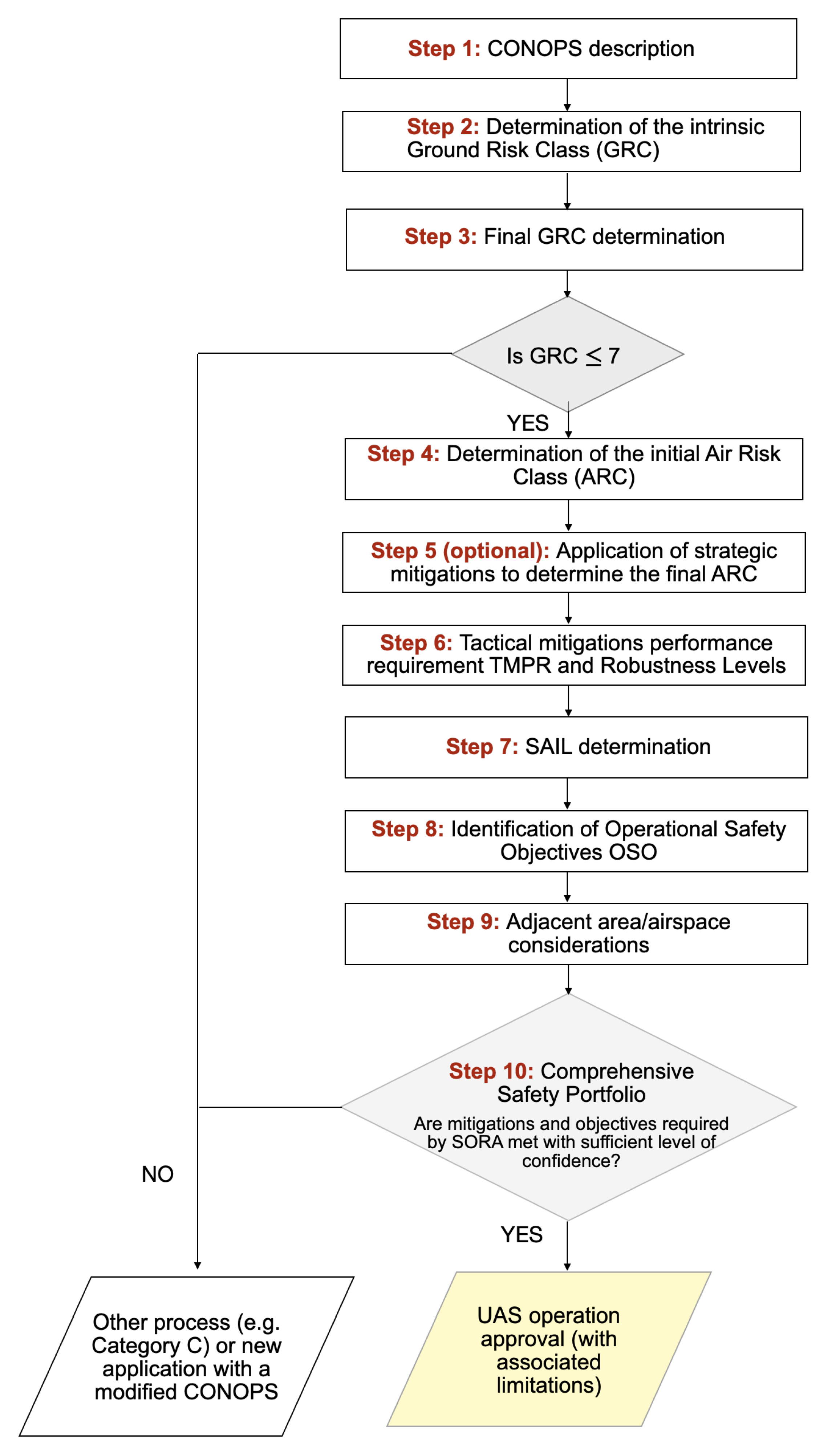
4.2. Step 1: CONOPS Description

The CONOPS is a description of the mission from beginning to end with the aim of specifying the safety and performance requirements of the operation. The CONOPS describes the roles and responsibilities of the different actors and entities involved in the operation, the performance and safety requirements, and a description of the UAS that will be used for the operation. The CONOPS is considered a live document, and it will be modified repeatedly to adapt the operation according to the recommendations provided after conducting the risk assessment.
In the operation described in this paper, the task of the Multi-UAS was to fly in semi-autonomous mode around the airframe, gathering visual data for inspection purposes, ensuring the safety of the operation, and the operational condition of the inspected airframe. A CONOPS was developed for the multi-UAS AFI operation. Section 3 presents a summary of the CONOPS. The complete document can be accessed in [25].

4.3. Step 2: Determination of the Intrinsic Ground Risk Class

The intrinsic ground risk class (GRC) analyzes the unmitigated risk of the following event, when a UAS is out of control and strikes a person.Defining the intrinsic GRC of the operation entails using the information presented in the SORA methodology, “Table 2. Determination of the intrinsic GRC” (page 20) from [10]. The table considers the operation scenario (VLOS, BVLOS, etc.) and the size of the UAS (dimension and expected kinetic energy).
For the Multi-UAS AFI operation, the intrinsic ground risk class was GRC = 2. This value was selected taking into account the following information from Table 2:
  • The intended operation will be conducted at VLOS.
  • The dimension of the UAS is in the range of 1–3 m.
  • The kinetic energy is 3.4 KJ.

4.4. Step 3: Final Ground Risk Determination

The previously defined intrinsic GRC can be reduced by applying specific mitigation strategies. Table 3 presents the reductions that can be obtained, depending on the employed mitigations, and their level of robustness.
M1 strategic mitigations for ground risk focus on reducing people at risk. M2 mitigations (to reduce the effects of ground impact) focus on reducing the energy absorbed by the people on the ground upon impact (e.g., by using a parachute). On the other hand, M3 mitigation is claimed when an Emergency Response Plan (ERP) is in place. Annex B of the SORA methodology can be used to understand the different mitigation strategies and to analyze and determine the level of integrity and assurance of such mitigations [30].
For the Multi-UAS AFI operation, we claimed the following M1 mitigations for reducing the ground risk class: a tethered system will be used. For this mitigation, we claimed a high level of integrity and assurance taking into account the following considerations.
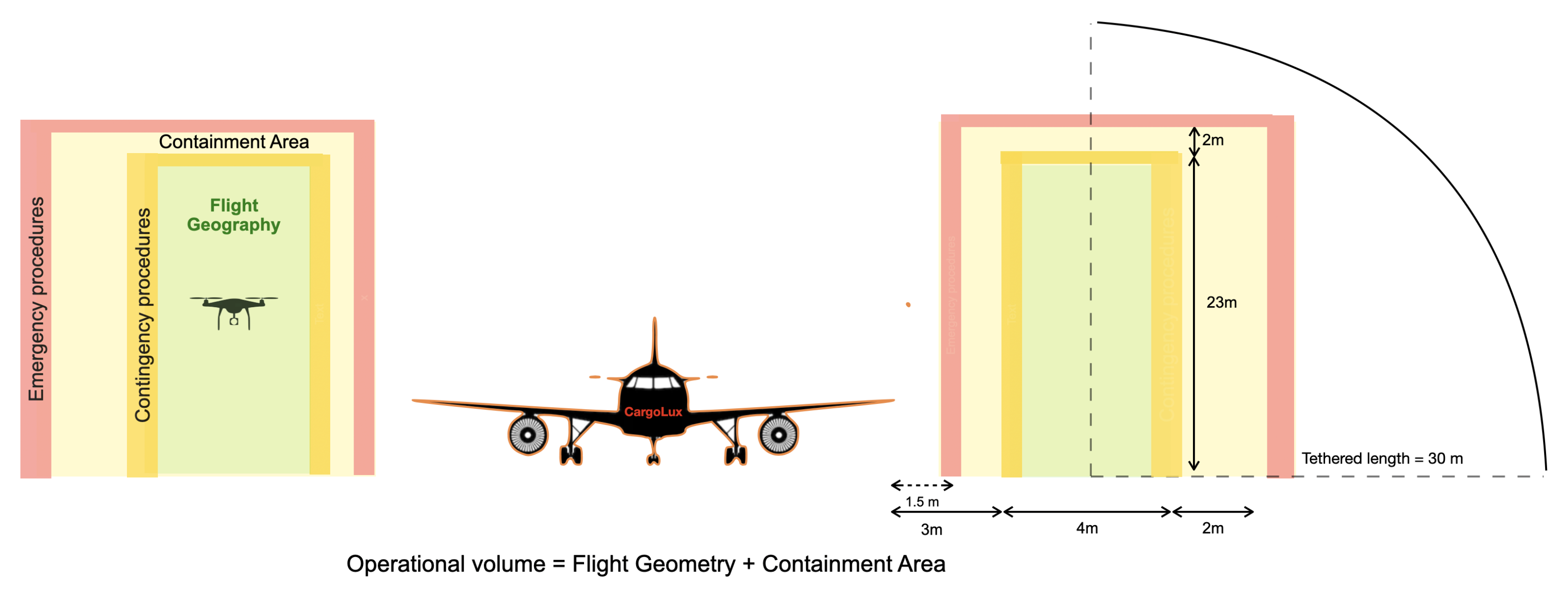
  • The length of the tethered system is 60 m which is adequate to contain the operational volume (described in Figure 2). During the operation, the length will be limited to 30 m.
  • The specifications of the tethered system shows that the strength of the line is 150 kg of traction, which is adequate to contain the UAS load. The strength of the attachment points is compatible with ultimate loads, and it cannot be cut by rotating propellers. Performance tests of the system are available.
  • The tether system corresponds to the one offered by a well-known manufacturer (SAFE-T system from Ellistar [26]), with experience in applying its system to several UAS-based applications in different countries (Sweden, France, Austria, among others).
An important aspect when applying mitigations M1 is that the intrinsic GRC cannot be reduced to a value lower than the lowest value of the column used to calculate the intrinsic GRC. The intrinsic GRC already corresponds to the lowest value of the column (i.e., 2). Consequently, for the Multi-UAS AFI operation, mitigation M1 (i.e., a tethered system that could allow a reduction of −2) does not have any effect on the final GRC for this scenario. Therefore, the final GRC is Final GRC = 2, which is considered a low GRC.
In addition to the previously mentioned mitigations, the Multi-UAS AFI operation included the following features that enabled further containment of the ground risk:
  • The Multi-UAS operation ensures a ground risk buffer with a 1 to 1 rule (if the UAS operates at 23 m, the ground risk buffer is minimum 23 m).
  • To reduce the risk of collision with the airframe, the UAS uses calibration and pre-planning strategies that identify the location of the airframe and plans the trajectories, ensuring the airframe is considered a NO-FLY zone.
  • The operation will be conducted in a controlled ground area, ensuring that there will be zero non-active participants in the area; participants will be only those in charge of the operation.
  • The operation will be conducted at a low speed below 3 m/s. This value is set internally and used so that the calculated trajectories do not exceed this value.

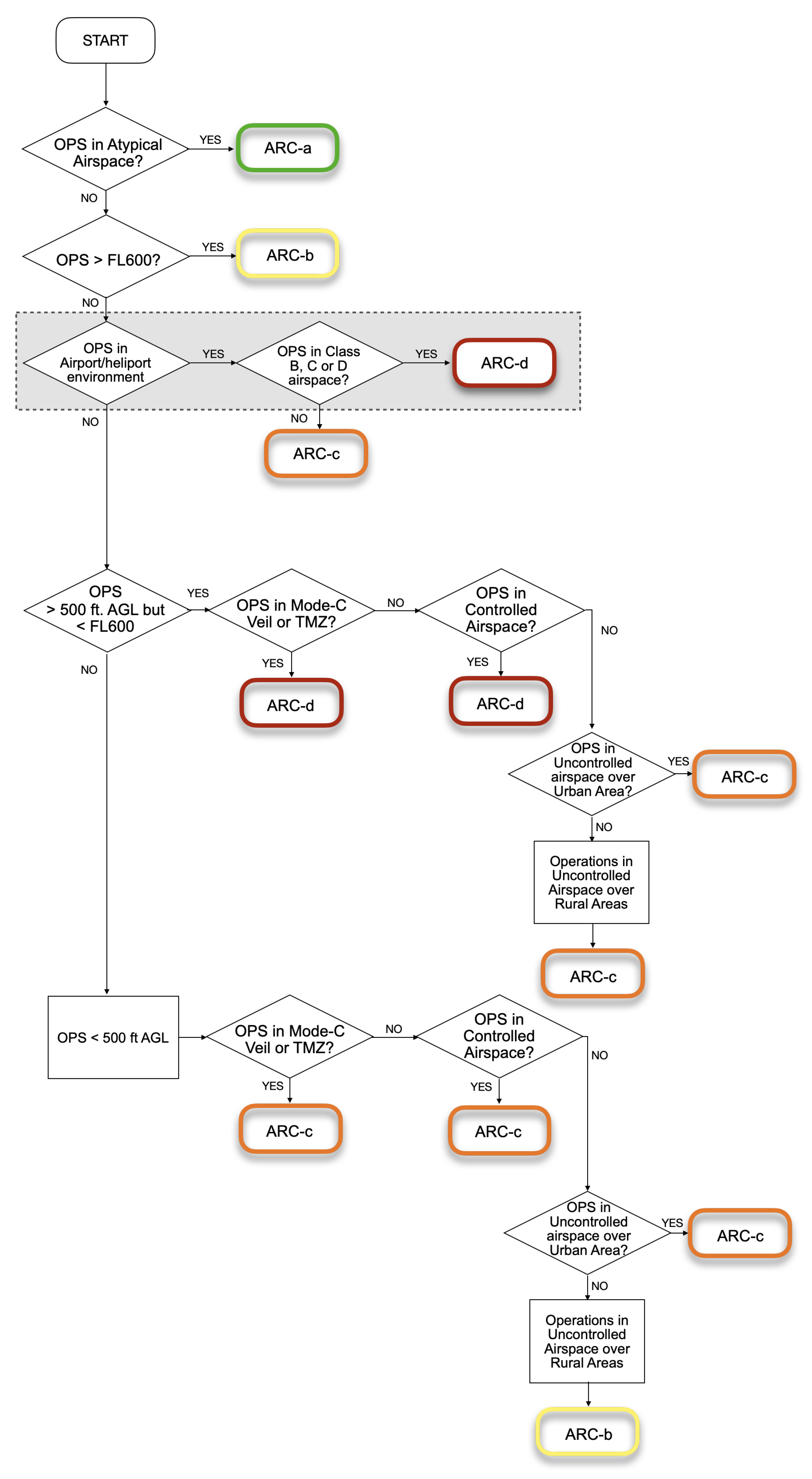
4.5. Step 4: Initial Air Risk Class ARC

The ARC is “a qualitative classification of the rate at which a UAS would encounter a manned aircraft in typical generalised civil airspace” [10]. It is important to keep in mind that the SORA methodology is limited to the risk of encountering a manned aircraft (i.e., piloted by a human onboard). Risks related to encounter other UAS are not considered by the methodology.
Figure 5 presents the decision tree provided by SORA to find the initial ARC, where the airspace has been divided into 13 aggregated collision risk categories (Figure 4, page 23 in [10]).
Based on Figure 5, the initial ARC for the Multi-UAS AFI operation was ARC-d, which coincided with airspace with a high risk of collision between a UAS and manned aircraft. This conclusion was derived taking into account that the Multi-AFI operation would be conducted in the Luxembourg airport and that the airspace class for the airport is D, according to [31].

4.6. Step 5: Strategic Mitigations to Determine Residual ARC

Strategic mitigations can be applied to reduce the initial ARC for the specific conditions of the intended operation. The mitigations work by application of operational restrictions or by application of common structures and rules. The SORA methodology provides a method to reduce the initial ARC by operational mitigations. Table 4 (Annex C [32]) can be used to determine a new ARC, when the operator considers its ARC should be lower than that found initially. The first column shows the associated airspace density rating (5 very high, 1 very low) for that initial ARC (second column). The third column is key to lower the ARC. It corresponds to the density ratings the operator should demonstrate in order to reduce the ARC to the one shown in the fourth column of the table. To claim the reduction, the airspace density of the operational area should be analyzed to show that the local airspace (fourth column) is lower than the generalized one (first column).
Mitigation by operational restrictions aim at mitigating the risk before takeoff. For the Multi-AFI operation, we claimed a reduction in the initial ARC-d to ARC-b by applying operational mitigations, because of the following:
  • The operational volume of each UAS will be restricted, see Figure 2. Apart from the tethered system, each UAS operates on a different side of the airframe at VLL airspace.
  • Each UAS will share its current position with the other UAS. During the execution of the different behaviors, this information will be used to monitor the mission (if their relative position corresponds to the one planned). It will also be used to cancel the execution of a specific trajectory if the UASs approach each other beyond the thresholds defined for the mission.
  • The density rating of manned aircraft at Luxembourg airport is low [31]. Additionally, The operation will be conducted at VLL (Very Low Level) airspace (max 30 m).
Although we do not claim specific reduction by common structures and rules, it is important to keep in mind that the VLL airspace corresponds to an airspace that is not used by manned aircraft (altitudes lower than 150 m). Therefore, following the advice on pages 9 and 15 from [32], the Multi-UAS AFI operation could also claim mitigations of the form of common airspace structure. Considering all the above arguments, the residual ARC for the Multi-UAS AFI operation was ARC-b.

4.7. Step 6: Tactical Mitigation Performance Requirement TMPR and Robustness Levels

These mitigations are applied after takeoff with the intention of mitigating any residual risk of a mid-air collision. They correspond to procedures that occur in a very short time horizon. SORA proposes different mitigation strategies depending on the type of operation [10].
For the Multi-UAS airframe inspection operation, the following tactical mitigations apply:
  • Operating at VLOS is by itself considered acceptable tactical mitigation. According to Section 2.4.4.1, paragraph b (Page 24) from [10]: “Flights under VLOS do not need to meet the tactical mitigations performance requirements nor the tactical mitigation robustness requirements”.
  • The crew always includes the Coordinator, the RPIC, the GCSO, and the VOs, which will keep the operation always at VLOS. The Coordinator, the RPIC and/or the VOs are in charge of detecting the aircraft using visual observations (conducting the “see” strategy). On the other hand, the RPIC or the GCSO are responsible for conducting the “avoid” strategy.
VLOS provides sufficient mitigation for the residual ARC. The Multi-UAS AFI operation uses independent RPCI, GCSO, and VO per UAS, in addition to a shared information system where each UAS and GCS have information of the position of each UAS. These strategies allow the mitigation of collision risk to manned aircraft (evaluated by the SORA methodology) and other UAS that are part of the operation (which is an aspect not covered by SORA).

4.8. Step 7: SAIL Determination

After estimating the final GRC and the residual ARC, the Specific Assurance and Integrity Level (SAIL) is estimated. The SAIL value defines the activities required to be conducted to ensure that the operation will stay under control. There are six (6) possible levels. A high SAIL value means that the operation is of high risk, and therefore the number of required safety objectives is high with a high level of robustness. Table 5 from SORA is used to determine the SAIL level for an operation. For the Multi-UAS AFI operation, the shadowed cells in Table 5 show the SAIL values that correspond to the GRC = 2 and ARC = b. Therefore, for the Multi-UAS AFI operation the SAIL = II.

4.9. Step 8: Identification of Operational Safety Objectives (OSO)

The last step of the SORA methodology is the definition of the Operational Safety Objectives required for the operation and their respective level of robustness. SORA provides a list of OSOs of common strategies used by experts to ensure safety in the UAS operation. Table 6 presents the recommended OSOs and the required level of robustness which depend on the SAIL level defined in Step 9. The level of robustness is represented by O (optional), L (recommended with low robustness), M (recommended with medium robustness), and H (recommended with high robustness). Annex E [33] of SORA provides details of the integrity and assurance levels for each OSOs.
Taking into account the SAIL level II of the operation (see shadowed cells in Table 6), from the 24 OSOs available for the Multi-UAS AFI operation six (6) of them are optional OSOs, fourteen (14) recommended of low robustness and four (4) recommended of medium robustness.

4.10. Step 9: Adjacent Area/Airspace Considerations

This step analyses the risk (ground/air) concerning the adjacent areas in case of a loss of control, resulting in the UAS infringing the operational volume. For the Multi-UAS operation, we can ensure that the probability of the UAS leaving the operational volume is very low due to the different safety features included in the operation.
  • Both UAS are tethered.
  • By default, the software running the UAS limits the operational volume that each UAS can fly over, by defining NO-FLY zones.
  • The safety features of the UAS from factory ensures the UAS does not leave the operational volume by using flight limits and flight restriction areas, and failsafe functions.
  • The operation is conducted at VLOS at VLL airspace.

4.11. Step 10: Comprehensive Safety Portfolio

The following list presents the OSOs; the required level of robustness according to Table 6; and the way the Multi-UAS AFI operation tackles the different safety objective, not only the ones required for the operation (with L and M robustness) but also others that have been identified as optional (O) that are considered essential for the Multi-UAS AFI operation:
  • OSO #01 (L) The concept of operation developed in the Multi-UAS AFI project included the description of the operational procedures, checklists, maintenance guidelines, training, and responsibilities and duties of the operator (CONOPS Sections 2.1 and 3.3 [25])
  • OSO #02, #04, #05 (O according to SORA, but we reached M for Multi-UAS AFI The UAV used in the operation corresponded to a well-known manufacturer (DJI), which demonstrates compliance with different standards and/or regulations [34]. Safety analyses were conducted during preflight and post-flight inspections (CONOPS Sections 3 and 4 [25])
  • OSO #03, #07 (L according to SORA, but we reached M for Multi-UAS AFI) Members of the control team have experience to conduct maintenance on the UAS. The Control Team has been trained to perform the UAS inspection following manufacturer procedures. (CONOPS Sections 2 and 4 [25])
  • OSO #06, #13 (L) The UAS allowed the control team to monitor the performance of the UAS, GPS signal strength, flying mode, UAS altitude, battery levels, C2 link signal strength, among others. Additionally, the UAS generated different alerts when signals became low. (CONOPS Section 4 [25]).
  • OSO #08, #11, #14, #21 (M) Operational procedures were defined for the operation. The Multi-UAS AFI CONOPS compiled preflight, inflight and post-flight procedures (UAS inspections, evaluation of environmental condition, emergency management), normal procedures, and contingency and emergency procedures. Contingency and emergency procedures required the RPIC to take control of the UAS when it was in automatic or autonomous mode. The CONOPS also included information of the limitations of the external systems supporting the operation. The different checklists of the procedures mitigated the risk of potential human errors. Emergency procedures were designed and tested by the manufacturer [35]. Contingency procedures were tested and validated with the PX4 SITL (Software In The Loop) (PX4 Gazebo simulator https://dev.px4.io/v1.9.0_noredirect/en/simulation/ (accessed on 7 October 2021)), CONOPS Sections 3 and 4 [25].
  • OSO #09, #15, #22 (L) The crew was made up of people with more than eight years of experience in the operation of UAS from different manufacturers, trained to identify and react to abnormal situations. The crew training program was documented in the CONOPS (Section 2.2 in [35]). It included training in the operational, emergency, and contingency procedures. The RPIC was a certified pilot, whose training included knowledge in UAS regulation, aviation safety, meteorology, among other aspects.
  • OSO #10, #12 (L) The autopilot included a module for autonomous emergency management which would guide the UAS to a safe landing point [35].
  • OSO#16 (L) The roles and responsibilities of each member of the crew and their role in the procedures were clearly defined. The flight team used communication devices (when required) that enabled active communication of the team during the operation. Remote Crew training covered multi-crew coordination (CONOPS Section 2 [25]).
  • OSO#17 (L) The Mission Coordinator ensured the crew was fit to operate before and during the operation.
  • OSO#18 (O according to SORA, but we reached L for Multi-UAS AFI) The flight control system incorporated functions that provided automatic protection of the flight envelop. Flying boundaries were specified taking into account the airframe location to define no-fly zones. This information was used by the trajectory planner to plan trajectories only in the allowed areas (CONOPS Section 5 [25]).
  • OSO #19 (O according to SORA, but we reach considered L for Multi-UAS AFI) The roles of each member of the crew were clearly defined in the CONOPS. Different checklists mitigated the risk of potential human errors. The crew was trained to follow the procedures and to conduct the checklists (Multi-UAS CONOPS [25]).
  • OSO #20 (O according to SORA, but considered L for Multi-UAS AFI) The operation considered the use of a Ground Control Station per UAS with its specific operator. It reduced the operator workload and facilitated the monitoring of the operation. The HMI was used in different flight tests and it was found to be appropriate for the operation, it enabled monitoring of the performance of the UAS and receiving different alerts from the UAS.
  • OSO #23 (L) Environmental conditions for safe operation were specified in the CONOPS and the preflight checklist included the evaluation of the conditions.
  • OSO#24 (O according to SORA, but considered L for Multi-UAS AFI) The UAS used in the operation was from a well-known manufacturer. The environmental conditions defined in the CONOPS followed the UAS manufacturer (CONOPS Sections 3 and 4 [25]).

5. Discussion

The following paragraphs present key findings after following the SORA methodology for a Multi-UAS AFI operation at VLOS in an airport:
  • A critical component for succeeding in applying SORA is the definition of the operation, which requires a balance between succeeding with the mission’s objectives and succeeding in mitigating its risks. When we started analyzing the risk of the operation, we started to distinguish between flying one UAS at a time (relay scenario) or flying two UAS simultaneously (concurrent scenario). After analyzing the SORA for each scenario individually, we found that both strategies resulted in a low-risk operation, and therefore, in this paper, we focused on the concurrent scenario. In light of the new regulatory framework, operators should focus on designing operations from the application and the regulation point of view. Adopting this safety-focused practice will facilitate the approval process and will ensure that the operation is conducted safely.
  • The SORA methodology offers standard scenarios for the Open and Specific categories to facilitate the approval process of UAS operations. These are scenarios with precise safety requirements that are difficult to comply with for many operations (e.g., required air and ground risk buffers), and additional efforts are required to justify the pertinence of applying to those scenarios by claiming specific mitigation strategies. The Multi-UAS AFI operation could not use the available standard scenarios mainly because they do not support autonomous or Multi-UAS operations.
  • After applying SORA, it was found that the most critical aspect, in terms of risk, of the Multi-UAS AFI operation is related to the place of the operation. The Multi-UAS AFI operation would be conducted in an airport, which corresponds to a high Air Risk Collision class ARC-D (the number of UASs does not affect this classification). However, as suggested by the SORA methodology, it is possible to claim to the competent authorities strategic mitigations to reduce the ARC. For the Multi-UAS AFI operation, the tethered system and the strategic separation of the operational volume of each UAS helped to reduce the risks of the operation. Nevertheless, for Multi-UAS scenarios, SORA should be extended to include the risk of collision among UAS and not solely the ones related to manned aircraft.
  • After following the SORA methodology, it was found that the required level of robustness in OSOs related to the UAS and the crew, was lower than the one reached by our operation. It is important to remember that SORA was not explicitly designed for multi-UAS operations. Therefore, the results of SORA should be carefully analyzed and used as a starting point to ensure safety in the operation, especially for the Multi-UAS scenario.
  • A drawback found when exploring the SORA methodology was the limited information related to automatic and or autonomous operations with UASs. Most of the available UASs now allow this kind of operation. In this regard, the SORA methodology should be more detailed and provide additional guidance on the safety-related considerations associated with these capabilities.
  • The analysis conducted of the new European regulatory framework [9] showed that the Multi-UAS AFI operation fell under the Specific category due to the use of more than one UAS simultaneously with autonomous features. Therefore, a specific operation risk assessment was required for this operation. Following the SORA process recommended by EASA, it was found that the Multi-UAS AFI operation could be conducted, ensuring safety. The final GRC was 2, the final ARC was ARC-b, and the determined SAIL was II, which correspond to low-risk operations. Although the SORA methodology does not explicitly address the operation of multiple UAS, we have found that if it is carefully applied, it can bound the risk of these types of operations.
  • This study reveals that the SORA methodology can significantly constrain a multi-robot operation. For the Multi-UAS AFI operation, it was mandatory to segregate the airspace, include physical mechanisms such as the tethering system and reduce the autonomous behaviors of the UAS to keep the risk levels low. Because of this, urgent actions are needed to extend SORA to autonomous Multi-UAS scenarios.

6. Conclusions

This paper presented the application of the Specific Operation Risk assessment (SORA) methodology to the Multi-UAS airframe inspection operation, carried out under the framework of the SAFEMUV project. The paper applied step by step the SORA methodology and analyzed the implications of a multiple UAS scenario. Furthermore, we provided details of the CONOPS designed for the Multi-UAS AFI operation. In addition to this, we presented how the designed operation complies with the OSOs provided by SORA, and we discussed possible modifications/extensions of OSOs with their level of robustness relevant for a multi-UAS scenario. Through this specialized methodology, we established that although SORA does not explicitly include multiple UAS, the current methodology can be used to bound the risk of such operations. Nevertheless, additional efforts are still required to mitigate the risk of Multi-UAS operations with a high level of autonomy, where UAS are not tethered and have shared operational volumes. To this, operators and competent authorities should work together to extend SORA and to define standard scenarios that include both autonomous and multiple UAS operations. Our future work aims at proposing a comprehensive methodology for simulation-based systematic safety assessment of Multi-UAS that explicitly assesses the autonomy of UAS by enabling autonomous operations through safety assurance. This methodology could complement SORA and deduce acceptable means of compliance for the simulation environment to enable simulation results to certify complex autonomous operations before deploying the system in the real world.

Author Contributions

Conceptualization, C.M., P.J.S.-C. and S.G.; methodology, C.M.; software, P.J.S.-C.; validation, C.M. and P.J.S.-C., formal analysis, C.M.; investigation, C.M., P.J.S.-C. and A.B.; visualization, C.M. and P.J.S.-C.; writing—original draft preparation, C.M.; writing—review and editing, C.M., P.J.S.-C., A.B., S.G. and M.A.O.-M.; project administration, S.G. and M.A.O.-M.; funding acquisition, S.G. and M.A.O.-M. All authors have read and agreed to the published version of the manuscript.

Funding

This research was funded by the European Union’s Horizon 2020 project SESAME (grant agreement No 101017258) and by the Lloyds Register Foundation under the Assuring Autonomy International Programme grant SAFEMUV.

Institutional Review Board Statement

Not applicable.

Informed Consent Statement

Not applicable.

Data Availability Statement

Not applicable.

Acknowledgments

This research was supported by the European Union’s Horizon 2020 project SESAME (grant agreement No 101017258) and by the Lloyds Register Foundation under the Assuring Autonomy International Programme grant SAFEMUV.

Conflicts of Interest

The authors declare no conflict of interest.

Abbreviations

The following abbreviations are used in this manuscript:
SORASpecific Operation Risk Assessment
OSOOperational Safety Objectives
GRCGround Risk Class
ARCAir Risk Class
STSStandard Scenario
ERPEmergency Response Plan
AFIAir Frame Inspeciton
ANAAir Navigation Administration
VLLVery Low Level
TMPRTactical Mitigation Performance Requirement
SAILSpecific Assurance and Integrity Level
CONOPSConcept of Operations
EASAEuropean Aviation Safety Agency
UAVUnmanned Aerial Vehicle
IMUInertial Measurement Unit
GPSGlobal Positioning System
RTHReturn to Home
GCSOGround Control Station Operator
VOVisual Observer
VLOSVisual Line-of-Sight
BVLOSBeyond Visual Line-of-Sight
JARUSJoint Authorities for Rulemaking on Unmanned Systems
MTOMMaximum Takeoff Mass
ANSPAir Navigation Services Provider
GCSGround Control Station
RPICRemote Pilot-in-Command

References

  1. Robotics 2020. Multi-Annual Roadmap for Robotics in Europe. Horizon 2020 Call ICT-2016. Available online: https://www.eu-robotics.net/sparc/upload/about/files/H2020-Robotics-Multi-Annual-Roadmap-ICT-2016.pdf (accessed on 12 December 2020).
  2. Jing, W.; Deng, D.; Wu, Y.; Shimada, K. Multi-UAV Coverage Path Planning for the Inspection of Large and Complex Structures. In Proceedings of the 2020 IEEE/RSJ International Conference on Intelligent Robots and Systems (IROS), Las Vegas, NV, USA, 24 October–24 January 2021; pp. 1480–1486. [Google Scholar] [CrossRef]
  3. Schmuck, P.; Chli, M. Multi-UAV collaborative monocular SLAM. In Proceedings of the 2017 IEEE International Conference on Robotics and Automation (ICRA), Singapore, 29 May–3 June 2017; pp. 3863–3870. [Google Scholar] [CrossRef] [Green Version]
  4. Potena, C.; Khanna, R.; Nieto, J.; Siegwart, R.; Nardi, D.; Pretto, A. AgriColMap: Aerial-Ground Collaborative 3D Mapping for Precision Farming. IEEE Robot. Autom. Lett. 2019, 4, 1085–1092. [Google Scholar] [CrossRef] [Green Version]
  5. Abdelkader, M.; Shaqura, M.; Claudel, C.G.; Gueaieb, W. A UAV based system for real time flash flood monitoring in desert environments using Lagrangian microsensors. In Proceedings of the 2013 International Conference on Unmanned Aircraft Systems (ICUAS), Atlanta, GA, USA, 28–31 May 2013; pp. 25–34. [Google Scholar] [CrossRef]
  6. Bailon-Ruiz, R.; Lacroix, S.; Bit-Monnot, A. Planning to Monitor Wildfires with a Fleet of UAVs. In Proceedings of the 2018 IEEE/RSJ International Conference on Intelligent Robots and Systems (IROS), Madrid, Spain, 1–5 October 2018; pp. 4729–4734. [Google Scholar] [CrossRef] [Green Version]
  7. Alotaibi, E.T.; Alqefari, S.S.; Koubaa, A. LSAR: Multi-UAV Collaboration for Search and Rescue Missions. IEEE Access 2019, 7, 55817–55832. [Google Scholar] [CrossRef]
  8. Scherer, J.; Rinner, B. Multi-UAV Surveillance With Minimum Information Idleness and Latency Constraints. IEEE Robot. Autom. Lett. 2020, 5, 4812–4819. [Google Scholar] [CrossRef]
  9. EASA. Easy Access Rules for Unmanned Aircraft Systems (Regulations (EU) 2019/947 and (EU) 2019/945). In European Union Easa E-Rules. Available online: https://www.easa.europa.eu/document-library/easy-access-rules/easy-access-rules-unmanned-aircraft-systems-regulation-eu#group-publications (accessed on 10 January 2020).
  10. JARUS. JARUS Guidelines on Specific Operations Risk Assessment (SORA) V2.0. Available online: http://jarus-rpas.org/sites/jarus-rpas.org/files/jar_doc_06_jarus_sora_v2.0.pdf (accessed on 10 July 2021).
  11. University of York, Safe Airframe Inspection using Multiple UAVs (SAFEMUV). Available online: https://www.york.ac.uk/assuring-autonomy/projects/unmanned-aerial-vehicles-safety/ (accessed on 3 October 2020).
  12. Capitán, C.; Capitán, J.; Castano, A.R.; Ollero, A. Risk Assessment based on SORA Methodology for a UAS Media Production Application. In Proceedings of the 2019 International Conference on Unmanned Aircraft Systems (ICUAS), Atlanta, GA, USA, 11–14 June 2019; pp. 451–459. [Google Scholar] [CrossRef]
  13. Miles, T.; Suarez, B.; Kunzi, F.; Jackson, R. SORA Application to Large RPAS Flight Plans. In Proceedings of the 2019 IEEE/AIAA 38th Digital Avionics Systems Conference (DASC), San Diego, CA, USA, 8–12 September 2019; pp. 1–6. [Google Scholar] [CrossRef]
  14. Terkildsen, K.H.; Jensen, K. Towards a Tool for Assessing UAS Compliance with the JARUS SORA Guidelines. In Proceedings of the 2019 International Conference on Unmanned Aircraft Systems (ICUAS), Atlanta, GA, USA, 11–14 June 2019; pp. 460–466. [Google Scholar] [CrossRef]
  15. JARUS. JARUS Guidelines on Specific Operations Risk Assessment (SORA) V1.0. Available online: https://rpas-regulations.com/wp-content/uploads/2017/07/170626_JARUS_SORA_Annex-1_Glossary_v1.0.pdf (accessed on 10 August 2020).
  16. Denney, E.; Pai, G.; Johnson, M. Towards a Rigorous Basis for Specific Operations Risk Assessment of UAS. In Proceedings of the 2018 IEEE/AIAA 37th Digital Avionics Systems Conference (DASC), London, UK, 23–27 September 2018; pp. 1–10. [Google Scholar] [CrossRef]
  17. Janik, P.; Zawistowski, M.; Fellner, R.; Zawistowski, G. Unmanned Aircraft Systems Risk Assessment Based on SORA for First Responders and Disaster Management. Appl. Sci. 2021, 11, 5364. [Google Scholar] [CrossRef]
  18. European Union Aviation Safety Agency. IP 122 Clarification of Definitions for General Visual (GVI), Detailed (DET), and Special Detailed (SDI) Inspections. Available online: https://www.easa.europa.eu/document-library/imrbpb-issue-papers/ip-122 (accessed on 3 October 2020).
  19. Vora, J.; Nair, S.; Gramopadhye, A.K.; Duchowski, A.T.; Melloy, B.J.; Kanki, B. Using virtual reality technology for aircraft visual inspection training: Presence and comparison studies. Appl. Ergon. 2002, 33, 559–570. [Google Scholar] [CrossRef]
  20. Malandrakis, K.; Savvaris, A.; Domingo, J.A.G.; Avdelidis, N.; Tsilivis, P.; Plumacker, F.; Fragonara, L.Z.; Tsourdos, A. Inspection of Aircraft Wing Panels Using Unmanned Aerial Vehicles. In Proceedings of the 2018 5th IEEE International Workshop on Metrology for AeroSpace (MetroAeroSpace), Rome, Italy, 20–22 June 2018; pp. 56–61. [Google Scholar] [CrossRef] [Green Version]
  21. Hrúz, M.; Bugaj, M.; Novák, A.; Kandera, B.; Badánik, B. The Use of UAV with Infrared Camera and RFID for Airframe Condition Monitoring. Appl. Sci. 2021, 11, 3737. [Google Scholar] [CrossRef]
  22. Interdisciplinary Centre for Security, Reliability and Trust. Airframe Inspection (AFI) Project; University of Luxembourg: Luxembourg, 2018. [Google Scholar]
  23. Dentler, J.; Kannan, S.; Bezzaoucha Rebaï, S.; Olivares-Mendez, M.; Voos, H. Model predictive cooperative localization control of multiple UAVs using potential function sensor constraints. Auton. Robot. 2018. [Google Scholar] [CrossRef] [Green Version]
  24. Donecle. Available online: https://www.donecle.com/ (accessed on 3 July 2021).
  25. Deliverable D1.1 of SAFEMUV Project. Concept of Operations; Assuring Autonomy International Programme (AAIP). Available online: https://drive.google.com/file/d/1z6d0PhiVUYv6qvdAbwE13CYtwTknUDgD/view (accessed on 23 November 2021).
  26. Elistair. ELISTAIR, The Tethered Drone Company. Available online: https://elistair.com/safe-t-tethered-drone-station/ (accessed on 20 October 2020).
  27. DJI. Matrice 600 User Manual. Available online: https://dl.djicdn.com/downloads/m600/20170717/Matrice_600_User_Manual_v1.0_EN.pdf (accessed on 15 October 2020).
  28. DJI. DJI Ronin-MX Gimbal. Available online: https://www.dji.com/lu/ronin-mx (accessed on 15 October 2020).
  29. EASA Opinion 05/2019. Standard scenarios for UAS operations in the specific category. In European Union EASA E-Rules; EASA: Cologne, Germany, 2020. [Google Scholar]
  30. JARUS. Annex B: Integrity and Assurance Levels for the Mitigations Used to Reduce the Intrinsic Ground Risk Class. Available online: http://jarus-rpas.org/sites/jarus-rpas.org/files/jar_doc_06_jarus_sora_annex_b_v1.0.pdf (accessed on 25 January 2021).
  31. LSSIP 2019 Luxembourg. Local Single Sky Implementation. Available online: https://www.eurocontrol.int/sites/default/files/2020-04/eurocontrol-lssip-2019-luxembourg-level1.pdf (accessed on 12 December 2020).
  32. JARUS. Annex C: Strategic Mitigation Collision Risk Assessment. Available online: http://jarus-rpas.org/sites/jarus-rpas.org/files/jar_doc_06_jarus_sora_annex_c_v1.0.pdf (accessed on 25 January 2021).
  33. JARUS. Annex E: Integrity and Assurance Levels for the Operation Safety Objectives (OSO). Available online: http://jarus-rpas.org/sites/jarus-rpas.org/files/jar_doc_06_jarus_sora_annex_e_v1.0_.pdf (accessed on 15 February 2021).
  34. DJI Matrice 600 Declaration of Conformity. Available online: https://d15bfve0bne4ko.cloudfront.net/Industrial/M600.pdf (accessed on 10 December 2020).
  35. DJI. Matrice 600 Safety Guidelines. Available online: https://dl.djicdn.com/downloads/m600/20170717/Matrice_600_Disclaimer_and_Safety_Guidelines_v1.2_EN.pdf (accessed on 5 October 2020).
Figure 1. Overview of the multi-UAS airframe inspection operation. Two tethered multirotor UAS flew around the airframe acquiring high-quality images, using independent operational volumes.
Drones 05 00141 g001
Figure 2. Operational volume for Multi-UAS AFI operation. Crossing the yellow and red lines would activate the contingency and emergency procedures, respectively. The UAS would never fly over the airframe.
Drones 05 00141 g002
Figure 3. Multi-UAS Airframe inspection strategy. The airframe is divided into two zones. Each UAS is responsible for inspecting one side of the airframe. The crew is formed by the Coordinator, two RPIC, two GCSO, and two VO. Each UAS has a Ground Control Station (GCS).
Drones 05 00141 g003
Figure 4. Steps of SORA methodology. Image adapted from [10].
Drones 05 00141 g004
Figure 5. Initial ARC assignment process. The dotted rectangle corresponds to the selection made for the Multi-UAS AFI operation. As a result, the initial ARC class is ARC-d. Image adapted from [10].
Drones 05 00141 g005
Table 1. UAS specifications for airframe inspection.
UAVDJI Matrice 600
Size1668 mm × 1518 mm × 759 mm (unfolded)
MTOM15.1 kg
Mx up-speed5 m/s
Mx down-speed3 m/s
Mx cruise speed18 m/s (without wind)
Max wind speed8 m/s
GPS RTKYes
RC and communicationLightbridge 2
FCUDJI A3
Tethered systemElistair SAFE-T
CameraCanon EOS 5DS R high resolution camera 50.6 Megapixel MP
GimbalDJI Ronin-MX gimbal [28]
Computer 1Raspberry Pi for medium level control system
Computer 2Nvidia Jetson for image acquisition.
Computer 3Intel NUC computer dedicated to High Level tasks such as path, trajectory planning, and collision avoidance
Table 2. Specification of the Multi-UAS AFI operation.
OperationAirframe inspection
Category (EASA)Specific
LocationLuxembourg airport
Type of airspaceControlled
Type of operationVLOS over controlled ground area
Flight conditionsDaytime and good weather conditions.
Max MTOM15.1 kg
Kinetic energy3.4 KJ
UAS categoryC3
UAS dimension1668 mm × 1518 mm × 759 mm
Max speed1 m/s
Flight geography limits3 m wrt airframe, 23 m above ground
Mode of operationsemi-autonomous
Use of visual observersYes
Number of UAS2
Number of RPIC2
TetheredYes
Min image resolution2 Megapixel
Min image overlap35% overlap
Min number of images acquired per point3 images
Table 3. Mitigations for determining the Final GRC [10].
Mitigations for Ground RiskRobustness
Low/NoneMediumHigh
M1—Strategic mitigations for ground risk0: None
−1: Low
−2−4
M2—Effects of ground impact are reduced0−1−2
M3—An Emergency Response Plan (ERP) is in place, operator validated and effective10−1
Table 4. Excerpt of guide to reduce the Initial ARC according to [32].
Initial Generalized Density Rating for the EnvironmentInitial ARCIf the Local Density Can Be Demonstrated to Be Similar toNew Lowered Residual ARC
5ARC-d4 or 3ARC-c
2 or 1ARC-b
4ARC-d3 or 2ARC-c
1ARC-b
3ARC-c1ARC-b
2ARC-c1ARC-b
3ARC-c1ARC-b
2ARC-c1ARC-b
Table 5. SAIL determination [10].
Residual ARC
Final GRCabcd
≤2IIIIVVI
3IIIIIVVI
4IIIIIIIVVI
5IVIVIVVI
6VVVVI
7VIVIVIVI
>7Category C operation
Table 6. Operational Safety Objective (OSOs) with the specific robustness level (‘O’: optional; ‘L’: recommended with low robustness; ‘M’: recommended with medium robustness; and ‘H’: recommended with high robustness).
OSO IDDescriptionSAIL
IIIIIIIVVVI
Technical Issue with the UAS
OSO#01Ensure the operator is competent and/or provenOLMHHH
OSO#02UAS manufactured by competent and/or proven entityOOLMHH
OSO#03UAS maintained by competent and/or proven entityLLMMHH
OSO#04UAS developed to authority recognized design standardsOOOLMH
OSO#05UAS is designed considering system safety and reliabilityOOLMHH
OSO#06C3 link performance is appropriate for the operationOLLMHH
OSO#07Inspection of the UAS (product inspection) to ensure consistency to the ConOpsLLMMHH
OSO#08Operational procedures are defined, validated, and adhered toLMHHHH
OSO#09Remote crew trained and current and able to control the abnormal situationLLMMHH
OSO#10Safe recovery from technical issueLLMMHH
Deterioration of external systems supporting UAS operation
OSO#11Procedures are in place to handle the deterioration of external systems supporting UAS operationLMHHHH
OSO#12The UAS is designed to manage the deterioration of external systems supporting UAS operationLLMMHH
OSO#13External services supporting UAS operations are adequate to the operationLLMHHH
Human Error
OSO#14Operational procedures are defined, validated, and adhered toLMHHHH
OSO#15Remote crew trained and current and able to control the abnormal situationLLMMHH
OSO#16Multi crew coordinationLLMMHH
OSO#17Remote crew is fit to operateLLMMHH
OSO#18Automatic protection of the flight envelope from Human ErrorOOLMHH
OSO#19Safe recovery from Human ErrorOOLMMH
OSO#20A Human Factors evaluation has been performed and the HMI found appropriate for the missionOLLMMH
Adverse operating conditions
OSO#21Operational procedures are defined, validated, and adhered toLMHHHH
OSO#22The remote crew is trained to identify critical environmental conditions and to avoid themLLMMMH
OSO#23Environmental conditions for safe operations defined, measurable, and adhered toLLMMMH
OSO#24UAS designed and qualified for adverse environmental conditionsOOMHHH
Publisher’s Note: MDPI stays neutral with regard to jurisdictional claims in published maps and institutional affiliations.

