Article

Suitability of the Reforming-Controlled Compression Ignition Concept for UAV Applications

Technion—Israel Institute of Technology, Technion City, Haifa 3200003, Israel
*
Author to whom correspondence should be addressed.
Drones 2020, 4(3), 60; https://doi.org/10.3390/drones4030060
Submission received: 1 September 2020 / Revised: 17 September 2020 / Accepted: 18 September 2020 / Published: 22 September 2020
(This article belongs to the Special Issue Feature Papers of Drones)

Abstract

:
Reforming-controlled compression ignition (RefCCI) is a novel approach combining two methods to improve the internal combustion engine’s efficiency and mitigate emissions: low-temperature combustion (LTC) and thermochemical recuperation (TCR). Frequently, the combustion controllability challenge is resolved by simultaneous injection into the cylinder of two fuel types, each on the other edge of the reactivity scale. By changing the low-to-high-reactivity fuel ratio, ignition timing and combustion phasing control can be achieved. The RefCCI principles, benefits, and possible challenges are described in previous publications. However, the suitability of the RefCCI approach for aerial, mainly unmanned aerial vehicle (UAV) platforms has not been studied yet. The main goal of this paper is to examine whether the RefCCI approach can be beneficial for UAV, especially HALE (high-altitude long-endurance) applications. The thermodynamic first-law and the second-law analysis is numerically performed to investigate the RefCCI approach suitability for UAV applications and to assess possible efficiency gains. A comparison with the conventional diesel engine and the previously developed technology of spark ignition (SI) engine with high-pressure TCR is performed in view of UAV peculiarities. The results indicate that the RefCCI system can be beneficial for UAV applications. The RefCCI higher efficiency compared to existing commercial engines compensates the lower heating value of the primary fuel, so the fuel consumption remains almost the same. By optimizing the compression pressure ratio, the RefCCI system efficiency can be improved.

1. Introduction

According to leading experts, the internal combustion engine (ICE) will keep being a prime propulsion tool for the next decades [1,2,3]. The ICE is also a major propulsion tool for unmanned aerial vehicle (UAV) applications including drones; while the main challenge and main global trend of the UAV industry are achieving high flight altitudes together with long endurance—HALE (high-altitude long-endurance). Higher flight altitude allows the covering of larger surfaces by one aircraft, more stealth, whereas long endurance makes longer times above an object possible . To be even more valuable for all platforms, the ICE has to significantly improve its energy efficiency to enable longer endurance. In recent decades, much work has been done to meeting this target. Low-temperature combustion (LTC) engines can increase engine efficiency and reduce pollutant emissions simultaneously [4,5]. This is possible since the combustion is simultaneous all over the cylinder resulting in eliminating the compression ratio (CR) restriction owing to the knocking phenomenon characterized in SI engines. In addition, the low-temperature combustion results in lower heat loss to the cylinder walls and NOx formation. However, the LTC engine has some challenges to be addressed before this approach can be commercial. The major challenges are ignition and combustion-phasing control, high CO and HC emissions, ringing, and limited operation range [4,5]. Several strategies to overcome these challenges have been proposed in recent years. Reactivity controlled compression ignition (RCCI) [6] and reforming-controlled compression ignition (RefCCI) [7,8,9] are two methods aiming to give a solution to combustion controllability and some additional LTC problems by adapting the charge reactivity to the engine operation regime. This is achieved by using two different fuel types—reactive and nonreactive (for instance: diesel and gasoline, respectively) [8]. Besides, these approaches offer different injection strategies aimed to moderate the heat release rate (HRR). Too high values of HRR might damage the engine structure.
Further efficiency improvement of LTC engines can be achieved by recycling a part of the available exhaust gas enthalpy. Thermochemical recuperation (TCR) is a promising approach enabling the efficient implementation of the latter approach [10]. TCR is based on utilizing the exhaust waste heat to sustain endothermic reactions of a primary fuel reforming in an onboard catalytic reactor [10]. As a result, the heating value of the produced new hydrogen-rich fuel (reformate) rises, with subsequent benefits in terms of efficiency and emissions mitigation [11,12]. Some recently published works suggest using TCR for reformate production from alcohol fuels, such as methanol and ethanol in SI engines. A novel method of high-pressure thermochemical recuperation (HP-TCR) preventing maximum power loss and abnormal combustion was developed by the Technion researchers [13]. This method is based on the direct injection of the gaseous reformate into the engine cylinders. To mitigate the work required to compress the reformate and allow its direct injection, which would make this method worthless, the authors suggested pressurizing the liquid primary fuel before its reforming [14]. Hence, the latter occurs at elevated pressure. Poran et al. [14] experimentally investigated the first ever prototype of ICE combined with the HP-TCR. The primary fuel was methanol and the burned reforming products comprised mainly from CO2 (up to 25% mol.) and hydrogen (up to 75% mol.). They reported a 19% to 30% relative gain in the indicated efficiency, and a more than 90% reduction in NOx, CO, and HC emissions compared to the gasoline-fuel reference case. The above-described HP-TCR method is a part of the RefCCI concept resulting in higher efficiency compared to RCCI because of waste heat recovery and hydrogen combustion.
A primary fuel fitting well for use in ICE with HP-TCR (it) is dimethyl ether (DME) [10]. DME is a nontoxic, low carbon intensity, noncorrosive, and not harmful to the ozone layer alternative fuel [15]. Its combustion normally produces lower particle, hydrocarbon, NOx, and carbon monoxide emissions [16]. DME has also challenging aspects that are related to its physical properties. DME is a gas at ambient conditions, which requires a sealed fuel supply system. DME viscosity is 20 times lower than that of diesel. This may cause leakage and lubrication problems in fuel pumps and injectors [16]. Therefore, the engine fuel system should be adapted to DME. DME has a low reforming temperature of 250–350 ℃, which enables efficient recovery of ICE exhaust gas energy. The main physical properties of DME, hydrogen, and some other fuels are listed in Table 1.
To overcome the challenges of catalyst coking, to avoid the need for multiple reformers, and enable the use of a single primary fuel, the reforming-controlled compression ignition (RefCCI) approach was suggested and analyzed by the authors in [7] and [9]. The RefCCI method couples the benefits of the HP-TCR and the advanced combustion concept, the reactivity-controlled compression ignition (RCCI) developed by researchers from the University of Wisconsin [6]. According to the RefCCI method, a part of the primary fuel is reformed using the steam reforming of DME (SRD) in a catalytic reactor [7] to create a hydrogen-rich reformate. Both the nonreformed high-reactivity primary fuel (DME) and the low-reactivity gaseous reformate (mainly H2) are injected directly into the cylinder in a controllably varied ratio. The simulation results [7] showed that, as a result of the heat recovery effect, only efficiency improvement of up to 5.4% is achieved compared to the basic engine without TCR. The predicted efficiency of the RefCCI engine was approximately 50% for a very basic engine configuration.
The second-law analysis is an accepted tool of recognizing ways to improve efficiency [19]. Mapping the exergy destruction causes allows redesign of the tested system to minimize exergy destruction [20] and consequently to improve system efficiency [21]. This approach is very common in many different engineering areas [22] such as gas turbines [23,24], power plants with CO2 capture [25], and organic Rankine cycle-based waste energy recovery [26]. The second-law analysis concept is also extensively applied in the ICE field. It begins with fundamental research [27,28,29] and continues to the analysis of engineering applications [30,31,32,33].
The second-law analysis of the RefCCI engine [9] showed that approximately 33% of the fuel exergy consumed by the system is destroyed owing to the irreversible process in the combustion chamber. An additional 5% is destroyed in the reforming system. Chemical reaction and in-cylinder gas to walls heat interaction are the major contributors to exergy destruction in the engine, accounting for approximately 45% and 38%, respectively. After the optimization of parameters affecting the exergy destruction, the obtained results revealed indicated efficiency improvement above 7%, and even higher if the compression ratio is increased.
The main goal of the reported study is to examine the suitability of the RefCCI concept to UAV applications with an emphasis on HALE (high-altitude long-endurance) platforms. Ambient conditions at high altitude require some adjustments to the RefCCI system. First, the known problem of limited power owing to reduced air density should be considered. Second, since the autoignition principle is applied in the RefCCI method, the pressure after compression has a very important role in enabling the charge compression ignition. Too low pressure may result in misfiring since the autoignition delay becomes longer with pressure reduction [5]. Turbocharging enables both challenges to be resolved. An intercooler usually is applied as well to reduce the compressed air temperature and increase further its density.
Considering the mentioned above, the issue that should be examined whether there is sufficient available exhaust gas energy for simultaneous powering the turbocharger turbine and sustaining the efficient reforming process. The enthalpy required by the latter increases so much as the required hydrogen flow rate is higher. This happens as the average pressure and temperature in the cylinder rise, for example with load increase. Boosting the air in the compressor on one hand increases the intake pressure and consequently, the average pressure and, on the other hand, decreases the average temperature during combustion owing to the air dilution effect. Therefore, the combined effect of over-boosting should be examined. If the engine demand for hydrogen is higher with boosting, the lack of available energy to operate both systems may be a realistic scenario. However, in this case, the produced turbine power is reduced resulting in lower boosting until the system arrives at a certain point enabling operation of both systems. Nevertheless, as mentioned above, if the intake pressure is too low combustion may not occur. This consequence can restrict the altitude range. Thus, this work investigates the ability of the boosted RefCCI system to operate at the HALE UAV conditions. The focus is on altitudes from 20,000 to 40,000 ft (approximately 6.1 to 12.2 km).

2. Methods

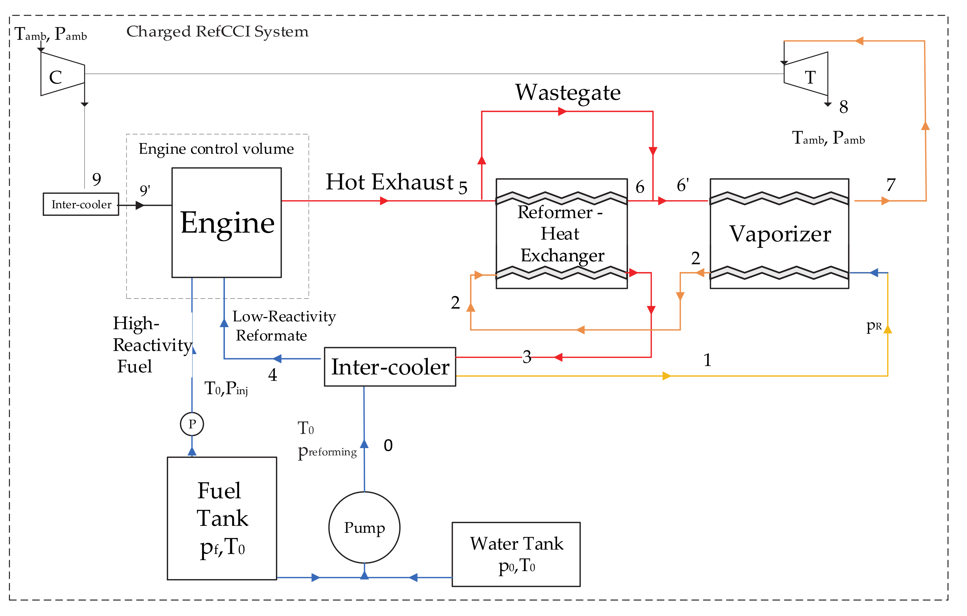
2.1. RefCCI Concept Description

The RefCCI concept uses a combination of RCCI [6] and HP-TCR [13] advantages with DME as a primary fuel and an onboard single-stage reformer filled with a bifunctional catalyst. In the RefCCI system, the engine exhaust gases are exploited to sustain endothermic reactions of fuel reforming in a single catalytic reformer. Three main reactions occur simultaneously in this reformer throughout the steam reforming of the DME (SRD) process. Each of them is supported by one of the catalyst functions (acid or metal): DME-hydrolysis (Equation (1), the opposite reaction to methanol dehydration), methanol steam reforming (SRM; Equation (2)), and reverse water gas shift (r-WGS; Equation (3)). These reactions and their enthalpy values are listed below:
C H 3 C H 3 g + H 2 O g 2 C H 3 O H g           Δ h = 24 k J / k g ,
2 C H 3 O H g + 2 H 2 O g 2 C O 2 + 6 H 2           Δ h = 50 k J / k g ,
C O 2 + H 2 H 2 O g + C O           Δ h = 41 k J / k g ,
The sum of the first two reactions gives:
C H 3 O H g + 3 H 2 O g 2 C O 2 + 6 H 2           Δ h = 139 k J / k g ,
The produced hydrogen-rich reformate is injected into the engine cylinder directly. DME is injected into the engine cylinder separately from the reformate. Combustion characteristics of DME and hydrogen differ substantially (the first is a high-reactive fuel and the second is a low-reactive fuel). The low-reactivity fuel has a shorter ignition delay than the high-reactivity fuel. Therefore, the increase of ratio between the injected low-reactivity primary fuel (DME) and the hydrogen-rich reformate results in advanced igniting timing and vice versa. Thus, varying this ratio can solve the controllability issue of compression autoignition (CAI) engines.

2.2. Model Description

The model used in this work is based on the previously developed two models described in [7,9]. The model is 1-D, homogenous combustion calculated using a reduced mechanism based on the work of Kaiser et al. [34]. The vaporizer, reformer, and intercooler are considered as adiabatic. The saturated water and DME thermodynamic properties are based on data from [18,35], respectively. The superheated water and DME vapors thermodynamic properties (considered as an ideal gas) were taken from NASA’s database [36]. The dependency of the ambient conditions on the flight altitude is shown in Figure 1.
The model numerically analyzes the RefCCI system (Figure 2) from both the first and the second law perspectives. As seen, the primary fuel (DME) and water are compressed and enter into the intercooler from the cool side. Then they enter into the vaporizer (pt. 1) to complete the evaporation process. The gas mixture flows into the reformer (pt. 2) and a low-reactivity hydrogen-rich reformate is obtained. The reformate is cooled down in the intercooler. In parallel, DME is injected directly into the engine cylinder. The reformer and vaporizer receive heat from the exhaust. The rest of the exhaust enthalpy is utilized to operate the turbine supplying power to the turbocharger compressor.
To simplify the model calculation, it is assumed that the DME and water stream in different pipes and mixing before entering the reformer (pt.2). Based on the first-law calculation, the model finds all states in the systems. Since DME has a lower saturation temperature than water, it evaporates first, probably almost entirely in the intercooler. The maximal temperature that the model allows in pt. 2 is 600 K even if the vaporizer can warm it to greater temperature. However, pt. 2 temperature may be lower than 600 K when no energy is available to warm up the flow to this temperature or T6′ is lower than 600 K. The chemical reaction rate is calculated according to the model proposed by Oar-Artera et al. [38]. The bifunctional catalyst in this chemical model is CuFe2O4/γ-Al2O3. This chemical model, in particular its mathematical description part, is explained in more detail in [7].
A full explanation about assumptions made, mathematical descriptions, and other useful details about the model can be found in [7,9]. The modeled engine specification is listed below in Table 2.
The previously developed model was modified for UAV propulsion conditions. The turbine and compressor sub-models are universally applicable and are not based on a specific commercial device, but the efficiency of 0.72 was selected for both and the turbine pressure ratio was obtained from Bernoulli’s principle where a wastegate is utilized to control this pressure ratio. The turbine power is then calculated using Equation (5).
W ˙ t u r b i n e = η T c p T i n , T m ˙ e x h a u s t 1 p o u t , T p i n , T γ 1 γ ,
Here, pin,T is the turbine inlet or engine exhaust pressure (pt. 7- Figure 2), pout,T is the turbine exit pressure assumed to be the ambient pressure, cp is the average specific heat of gas streaming through the turbine, Tin,T is the gas temperature at the turbine inlet, m ˙ e x h a u s t is the exhaust mass flow rate, η T is the turbine efficiency, and γ is the exhaust gas heat capacity ratio.
The power produced by the turbine is supplied to the compressor and, as a result, a compression pressure ratio is calculated using Equation (6).
W ˙ c o m p r e s o r = c p T i n , C η c m ˙ i n t a k e 1 p o u t , C p i n , C γ 1 γ ,
Here, pin,C is the compressor inlet pressure assumed to be the ambient pressure (pt. 7- Figure 2), pout,C is the compressor exit pressure, cp is the average specific heat of air streaming through the compressor, Tin,C is the air temperature at the compressor inlet, m ˙ i n t a k e is the intake air mass flow rate, η C is the compression efficiency, and γ is the intake air heat capacity ratio. Note that in this work a simple turbocharging system is thermodynamically modeled. In reality, a two-stage turbocharging could be required, as discussed in [39], to enable efficient system operation in real high-altitude flight conditions.
To reduce the reforming average temperature, the reformer wastegate opening degree (Figure 2) is controlled by a PID controller. The selected set-point is 600 K at the reformate exit (pt. 6, Figure 2), which is the temperature resulting in high fuel conversion according to chemical equilibrium considerations. Too high exhaust-side reformer temperature may result in extensive exergy destruction owing to a large temperature difference.
The surrounding reference state chosen for this analysis is the sea-level typical state meaning 25 ℃ and 1013 mbar. The environment is composed of N2 , O2 , H2O(g) , CO2, and other components in the molar fractions 75.67%, 20.35%, 3.12%, 0.03%, and 0.83%, respectively [35].
Notably, the general engine model uses existing and well-verified sub-models of the commercial GT-Suite SW. The latter is an extensively validated commercial SW widely used worldwide in engine research and development. Therefore, it was not essential to validate the engine model. As regards the reformer model, its validation for the methanol steam reforming reaction (SRM) was performed and described in detail in the previous publication of the Technion research group [14].

2.3. Second-Law Analysis

In each RefCCI component (Figure 2), the exergy destruction is calculated according to its thermodynamic classification and operating conditions. The reformer, vaporizer, turbine, compressor, and both intercoolers are assumed to be adiabatic and in steady-state control volumes. Among these parts, chemical reactions take place only in the reformer. In the model, the exergy destruction is calculated either by Equation (7) or by exergy balance—Equation (8).
B ˙ d = T 0 d S d t j Q ˙ j T j i n m ˙ i n s i n + o u t m ˙ o u t s o u t ,
Here, T 0 is the reference temperature, Q ˙ j is the heat interaction rate of the system with the walls, and T j is the wall j temperature.
B ˙ d = j 1 T 0 T j Q ˙ j W ˙ p 0 d V d t + i n m ˙ i n b f l o w , i n o u t m ˙ o u t b f l o w , o u t d B d t
where, b f l o w is the specific flow exergy including both thermomechanical and chemical exergy, b T M and b c h , respectively. To calculate exergy destruction in the reformer, intercooler, and evaporator the exergy balance was applied. Since these systems are assumed to be adiabatic in steady-state operation mode, only the exergy flows are considered.
For the combustion chamber, the integration of Equation (7) over an entire cycle results in the total exergy destruction in the combustion chamber per engine cycle. Thus, the engine exergy destruction rate in steady-state ( B ˙ d , e n g i n e ) is obtained by multiplying this term by the engine speed (RPM) and dividing by 120. The exergy destruction in the combustion chamber is a result of the three main irreversible processes: chemical reaction, heat interaction, and injection. When engine valves are closed, Equation (7) degenerates so only the entropy change in time and heat interaction take place. It is reasonable to relate the chemical reaction exergy destruction ( B ˙ d , c h e m ) to the change in entropy between EOI and EVO and exergy destruction due to heat interaction ( B ˙ d , h e a t   i n t e r a c t i o n ) to the sum of heat interactions between the combustion chamber and its walls during the same interval. The exergy destruction produced during injection is the total engine exergy destruction subtracted by the two mentioned above parameters.
For the turbine and compressor, the exergy destruction is obtained from the exergy balance derivative of Equation (8) as described in Equation (9).
B ˙ d = m ˙ b i n b o u t W ˙ ,
Here, m ˙ , b i n , b o u t , and W ˙ are the mass flow rate, inlet specific exergy, outlet specific exergy, and mechanical power of the turbine/compressor, respectively.
The engine second-law efficiency is defined as follows:
η e n g i n e 2 l a w = W ˙ m ˙ D M E , D I b D M E c h + m ˙ r e f o r m a t e b r e f o r m a t e ,
Here, m ˙ D M E , D I is the DME consumption of the DME directly injected into the cylinder, m ˙ r e f o r m a t e is the reformate consumption, and b r e f o r m a t e is the reformate exergy containing the chemical and thermomechanical exergy. Evidently, the chemical constituent is dominant.
The RefCCI system second-law efficiency is defined as:
η R e f C C I , s y s 2 l a w = W ˙ m ˙ D M E b D M E c h ,
Here, m ˙ D M E is the entire DME consumption and b D M E c h is the DME chemical exergy (Table 1).
Similarly, the system efficiency is defined as:
η R e f C C I , s y s = W ˙ m ˙ D M E L H V D M E ,
Where, L H V D M E is the DME lower heating value (Table 1).

3. Results and Discussion

3.1. Boosted RefCCI Analysis

3.1.1. The Effect of Boosting on RefCCI Engine Behavior

Since the RefCCI system works according to the autoignition principle, the conditions in the vicinity of TDC must be sufficient to enable the autoignition of the fuel–air mixture. In particular, the initial pressure at the beginning of the compression stroke has a crucial role since it determines the maximal pressure before TDC. If this pressure is too low, autoignition will not occur. At high altitude, the surrounding pressure is very low (Figure 1), and therefore boosting is required. Besides, to gain the advantages of low-temperature combustion (LTC), such as RefCCI, it would be beneficial to have the air–fuel mixture as lean as possible. This means that extra air should enter the cylinder which requires extra boosting. However, extra boosting might cause negative phenomena such as elevated backpressure in the exhaust. Hence, the compression pressure ratio has a range in which the engine can work and this range varies depending on engine operating mode and flight altitude. Note that, in this work, the boosting system is not studied, and the compressor and turbine efficiency are fixed at 0.72. However, the effect of changing the compression pressure ratio on the RefCCI system performance is examined.
Figure 3 shows this trade-off. When the compression pressure ratio increases, the air–fuel equivalence ratio (λ) expectedly increases as well. The extra air entering into the cylinder decreases the maximal temperature and consequently heat losses to walls. As a result, the indicated gross efficiency consistently increases when the pressure becomes higher. However, the higher pressure- ratio is, the higher the pumping losses. This results in a trend change and an optimum appearance when the indicated net efficiency is considered. Eventually, for the case illustrated in Figure 3 (30,000 ft), the optimal pressure ratio is 3.25. The system efficiency is higher than the engine efficiency by approximately 1.75–2 percentage points (absolute) owing to waste heat recovery. Another interesting trend that is unique to a boosted RefCCI compared with a naturally aspirated RefCCI [7,9] is that the required H2/DME ratio does not extendedly modify. This is probably because of the opposite trends that boosting causes. As much as more air enters into the cylinder, the average in-cylinder pressure during the compression stroke is higher resulting in lower required fuel reactivity (higher H2/DME ratio). However, since the air is also a diluter, higher dilution results in the lower average temperature, which demands higher fuel reactivity. The simulation results show that at a flight altitude of 40,000 ft, the minimal compression pressure ratio that achieves the required in-cylinder pressure before ignition (to allow autoignition) is 3.25 compared to 1.5 at 20,000 ft. In fact, the intake pressure enabling autoignition is around 0.7 bar, reflecting approximately a minimum of 35 bar maximal pressure before combustion.

3.1.2. Exergy and Energy Analysis

To understand better the reasons for process irreversibility in the RefCCI system, it is useful to map the exergy and energy flow inside the system. After that, by utilizing tools that can reduce the process irreversibility, the system efficiency can be enhanced. Figure 4 shows an example of an exergy and energy flow map for a single case of engine operation at 40,000 ft. altitude, while the compression pressure ratio is 3.25 and the engine power is 12.75 kW for a single cylinder (defined as 50% of the maximal power) and engine speed 5000 RPM.
The main exergy destruction source is the engine itself. The exergy destruction in the reformer and vaporizer is significant as well. Therefore, to improve the system efficiency this destruction should be reduced as much as possible. In this case (Figure 4), the relatively low compression ratio does not allow the supply of extra air, so the air–fuel equivalence ratio (λ) is very close to 1. This causes some bad consequences affecting energy utilization in the system. On the one hand, low λ causes high in-cylinder temperature increasing heat losses. Only part of this heat can be utilized to produce work, while the exergy transferred by heat interaction ( j T 0 / T j 1 Q j ) is the maximum work value that can be produced (according to Carnot). Evidently, additional tools are necessary to harvest this work. Consequently, the high in-cylinder temperature results in high exhaust gas temperature and therefore higher temperature difference between the exhaust side and the fuel/reformate side both in the reformer and the vaporizer. On the second hand, increasing λ requires higher compression pressure ratio which inevitably leads to higher exhaust backpressure. The latter may result in lower cycle work.
When analyzing the sources of exergy destruction in the cylinder, chemical and heat exergy destruction are the major contributors. Two main factors affect the chemical exergy destruction during combustion. First, the fuel properties: as much as the fuel contains more hydrogen, the chemical exergy destruction is lower since, for a constant amount of air, the number of product molecules becomes lower compared to the number of the reactants (air/fuel) molecules [40]. Second, the amount of air participating in combustion: the higher mass is, the higher the entropy change rate. Figure 5 illustrates this trend. Note that, in this graph and from now on, the relative difference (Ψi) in the parameter i value appearing on the vertical axis is defined as the following:
Ψ i = ψ i ψ r e f ψ r e f
Where Ψ i is the predicted parameter i value and ψ r e f is its value for the reference case. The reference case is the lowest investigated value (unless it is defined differently), meaning the relative difference for the reference case is by definition zero.
The H2/DME ratio value shown in Figure 5 is the value required to maintain the engine combustion process in such a way that CA50 would be the same and equal 10 degrees ATDC. Generally, the chemical destruction increases with the increase of the compression pressure ratio. However, its slope varies depending on the H2/DME ratio. In the range of 2.25–3.25, when the H2/DME ratio decreases, the chemical exergy destruction curve slope is sharper than between 3.5–4.5 when the H2/DME ratio increases.
Increasing compression pressure ratio has some more effects on the boosted RefCCI system. It reduces exhaust temperature and consequently decreases reformer exergy destruction. It causes more recovery of waste energy by the boosting system and, as a result, less energy/exergy flows through the system exhaust. However, the increase of the compression pressure ratio is not unlimited. It may result in the need for more complex compression procedures such as two-stage compression with its accompanying problems [39]. In Figure 6 the results of the simulation for 40,000 ft, 5000 RPM, and 50% power are presented. The results match the mentioned above qualitative considerations. As explained, the system exhaust exergy flow (pt. 8 in Figure 2) significantly decreases (up to 90%) when the pressure ratio increases. In parallel, the system intake exergy flow, which is negative because the surrounding pressure and temperature are lower than in the reference state, becomes lower meaning more air-flow enters the system. The exergy transferred by heat decreases since the average temperature in the cylinder is lower. Consequently, the second-law efficiency increases with the pressure ratio increase meaning DME exergy consumption is lower. The reformer and vaporizer exergy destruction both decrease since the exhaust temperature is lower resulting in lower heat transfer temperature difference.
In the previous study [9], the authors investigated the influence of various parameters on exergy destruction in the RefCCI system. Some of them could affect the RefCCI system performance somewhat differently at UAV-relevant conditions. In addition to the previously studied parameters, there are some additional ones, which are unique for UAVs. For instance, since the UAV engine typically operates at higher speeds than a typical automotive engine, for the same load, the required H2/DME ratio and, as a result, hydrogen consumption would be lower. Therefore, either the reformer can be smaller or the temperature difference inside the reformer can be lower, resulting in reduced irreversibility. Another parameter, the range of which changes in UAV applications, is the boosted air temperature after intercooling (hereinafter, intercooling temperature). At high altitudes, the ability to cool the compressed air is enhanced. On the one hand, extra cooling of the air enables charging more air into the cylinder resulting in lower heat losses. On the other hand, it increases the chemical exergy destruction. In addition, the heat rejected from the intercooler is lost. Figure 7 shows the influence of the reduction in the intercooling temperature on exergy destruction and second-law efficiency of the boosted RefCCI system. The reference case is a temperature of 25 ℃, while all other parameters remain constant. As can be seen from Figure 7, the exergy destruction in the engine itself grows slightly with the decrease of the intercooling temperature. This is a result of the increase in chemical exergy destruction, which is higher than the reduction of exergy destroyed owing to heat transfer to the cylinder walls. However, the reduction in exergy flowing out of the system leads to improvement of the second-law efficiency by almost 4% at the intercooling temperature of −25 °C compared to the 25 °C case (as a reminder, the ambient air temperature at the flight altitude of 40,000 ft is below −50 °C).
When optimizing the boosted RefCCI system according to the findings of this and the previous work [9], it is possible to enhance the system performance significantly. Table 3 shows a comparison between the two cases, the reference case, which is presented in Figure 4, and the optimized case. The parameters changed are also shown in the Table. The results show that although the engine exergy destruction slightly increases, the significant reduction in the reforming exergy destruction and the exergy lost with the exhaust flow result in an increase of almost 4% in the second-law efficiency of the boosted RefCCI system. We believe that extensive optimization including more parameters than those investigated in this work can lead to even higher improvement.

3.2. Comparison between the RefCCI Concept and HP-TCR and a Commercial SI Engine

In this section, the investigated boosted RefCCI approach is compared with the HP-TCR SI engine and a commercial Rotax 914 engine. The Rotax 914 is a gasoline SI four-cylinder engine. The prediction of its performance was carried out based on the model described in [41]. The HP-TCR method is explained in detail and its model is described in [13]. All models were adjusted to enable a comparison with the investigated boosted RefCCI engine. Both HP-TCR and RefCCI models simulate the engine modified from the Lester Petter AD1 commercial engine. Both concepts enable the use of a high compression ratio. The RefCCI since it is based on compression autoignition, and HP-TCR since the combusted fuel in this concept is hydrogen, which has strong resistance to the ringing phenomenon. This ability was proven in [42]. To enable a comparison between the engines of different displacement, the indicated mean effective pressure (IMEP) value was kept the same. The compared propulsion technologies are summarized in Table 4.
In the UAV field, reducing the aircraft mass has an important significance. Thus, the main parameter that should be examined is ISFC. Fuel consumption depends on both engine efficiency and fuel heating value. The HP-TCR and RefCCI concepts are beneficial from the efficiency point of view than the commercial SI Rotax 914 engine, since both enable the use of higher CR and combust hydrogen, the fuel with much higher burning velocity (to remind: the latter enables getting closer to the ideal Otto cycle). However, the conventional Rotax 914 engine uses gasoline as the primary fuel, and gasoline has a considerably higher lower heating value (LHV) than methanol and DME (44 MJ/kg compared to 19.92 and 28.9, respectively—see Table 1). Thus, even if the efficiency of HP-TCR and RefCCI are higher than the SI Rotax 914, still their ISFCs may be larger. Nevertheless, the HP-TCR and RefCCI have other advantages that in the future might be crucial such as using non-fossil alternative fuel and cleaner combustion.
For the purpose of comparison, equal conditions in intake were set—1.08 bar and 298 K. Three regimes were tested, all at 5000 RPM, where the indicated power was set to three values: 50%, 39%, and 29.5% of the maximal power defined as 25.5 kW per cylinder for the HP-TCR and RefCCI. The Rotax 914 displacement volume is 82.5% of the HP-TCR and RefCCI engine. Thus, the maximal power was reduced according to this value to keep the IMEP value unchanged.
Figure 8 shows the results for the tested cases. The efficiency of the RefCCI system is relatively higher than that of the HP-TCR by approximately 10% on average and that of the Rotax 914 by approximately 50% on average. In on-land applications, this is a huge advantage. Yet, in the aerial application, the fuel mass carried by the platform should be minimal and thus the fuel consumption is the main consideration. The results show that the ISFC of the RefCCI system and the Rotax 914 engine are very close (approximately 1.2% only higher in the RefCCI vs. the Rotax 914). This means that the efficiency enhancement compensates for the lower heating value of DME compared to gasoline. The HP-TCR system has fairly high efficiency but also high ISFC meaning that it is less applicable for UAV applications.
It should be noted that both HP-TCR and RefCCI require water for the reforming process [7]. This water was not considered as part of the fuel mass consumption since the water can be easily condensed and reused from the exhaust flow. In the RefCCI, to produce two molecules of hydrogen, a single molecule of steam is required ( C H 3 O C H 3 + 3 H 2 O 6 H 2 + 2 C O 2 ) and incomplete combustion from a molecule of hydrogen a single molecule of steam is formed ( 6 H 2 + 3 O 2 + 3.76 N 2 + 2 C O 2 6 H 2 O + 2 C O 2 + 11.28 N 2 ). In total, the ratio between the combustion-formed water molecules to the required for reforming molecules is two. In the HP-TCR, this ratio is 3. To condense this steam, even if the air-fuel equivalence ratio is high and as a result, the partial pressure of the exhaust steam is very low, the surrounding temperature is low enough to enable condensation in any case. Keep in mind that the steam partial pressure decreases with the increase of flight altitude, but the surrounding temperature decreases as well.
Besides DME, other fuels may be considered as a primary fuel for the RefCCI engine. For aerial applications, the primary fuel should have as high LHV as possible and together with the high system efficiency, the fuel mass consumption might be even lower than that achieved in the RefCCI engine with DME as the primary fuel. However, to the best of the authors’ knowledge, no relevant works dealing with this issue have been published yet, and further research is required.
Some challenges still delay the practical penetration of the RefCCI method into UAV applications. The major challenge is ringing, which is not unique for UAV only. However, it may be more significant in UAV applications. Ringing owing to rapid heat release rate may be more severe in UAVs because of reduced air mass entering the engine. Intensive research is ongoing nowadays to find solutions to this problem. Among possible solutions, suiting appropriate injection strategy enabling to restrain the heat release rate should be mentioned. Evidently, a practical implementation of the RefCCI engine in the UAV platform would be easier if an alternative non-fossil primary fuel with an LHV similar to that of diesel is applied.

4. Summary and Conclusions

In this work, the suitability of the reforming-controlled compression ignition for UAV application was examined. First, the influence of boosting on the RefCCI engine behavior was discussed, then an exergy analysis to map the sources of exergy destruction in the RefCCI system was executed, and possibilities of performance improvement were analyzed. A comparison of the RefCCI approach with the high-pressure thermochemical recuperation SI engine and the commercial SI Rotax 914 engine were carried out.
The main findings are listed below:
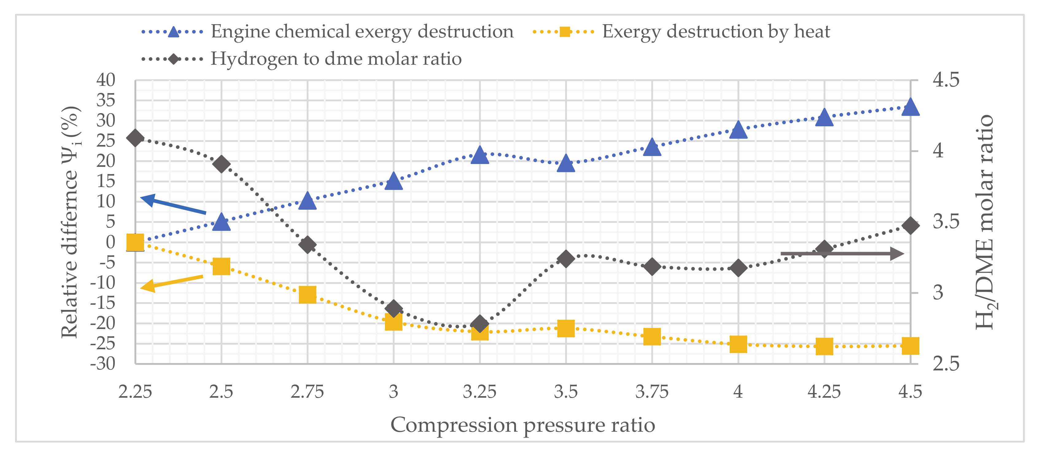
  • Increasing compression pressure ratio consistently increases the gross indicated efficiency of the RefCCI system, but this has also an opposite effect reflected in the pumping work increase. The net indicated efficiency has a maximum value where the first effect is the most dominant.
  • The necessary fuel reactivity (H2/DME ratio) varies only slightly with the increase of the compression pressure ratio and actually shows some volatility because of its opposite effects on autoignition timing. Increasing the compression pressure ratio, on the one hand, increases average pressure before combustion, but, on the other hand, decreases average temperature owing to the excess air dilution effect.
  • The RefCCI method seems to be a good alternative candidate for UAV application since, despite the relatively low heating value of DME, the high system efficiency leads to fuel consumption very close to that of the conventional gasoline engine.
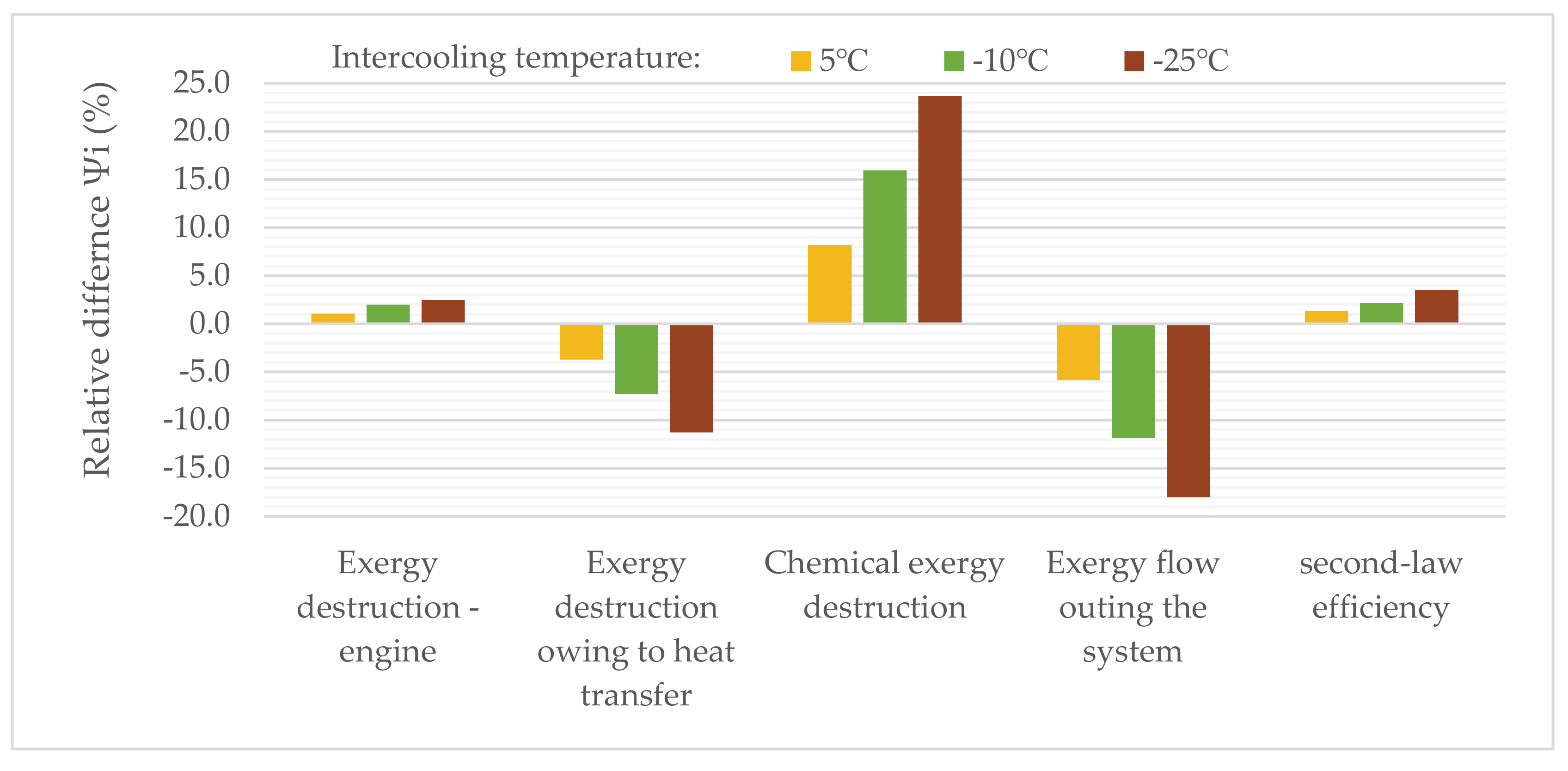
  • The results of the RefCCI system performance optimization show that a significant reduction in the reforming exergy destruction and the exergy lost with the exhaust flow can be achieved. This results in an improvement of almost 4% in the second-law efficiency of the boosted RefCCI system. We believe that extensive optimization including more parameters than those investigated in this work can lead to even higher improvement.
Besides DME, other fuels may be considered as a primary fuel for the RefCCI engine. For aerial applications, the primary fuel should have as high LHV as possible, and, together with the high RefCCI system efficiency, lower fuel mass consumption compared to other engine technologies may be achieved with cleaner combustion.
Experimental research of the RefCCI engine is necessary to better understand complicated processes taking place in the system in their mutual relationship. Developing injection strategies to restrain ringing in the engine cylinder is vital.

Author Contributions

Conceptualization, L.T. ; methodology, A.E. and L.T.; software, A.E.; validation, A.E.; formal analysis, A.E.; investigation, A.E.; resources, L.T.; data curation, L.T.; writing—original draft preparation, A.E.; writing—review and editing, L.T.; visualization, A.E.; supervision, L.T.; project administration, L.T.; funding acquisition, L.T. All authors have read and agreed to the published version of the manuscript.

Funding

This research was funded by the Israel Science Foundation, grant 2054/17 and Israel Ministry of Energy, grant 218-11-026.

Conflicts of Interest

The authors declare no conflict of interest.

Nomenclature

ATDCafter top dead center SRDsteam reforming of dimethyl ether
BBDCbefore bottom dead centerSRMmethanol steam reforming
BDCbottom dead center
BTDCbefore top dead center b c h specific chemical exergy
CAIcompression auto ignition B ˙ d exergy destruction rate
CRcompression ratio b flow specific flow exergy
DMEdimethyl ether b TM specific thermo-mechanical exergy
EOIend of injection m ˙ mass flow rate
EVOexhaust valve open s specific entropy
HALEhigh altitude long endurance γ heat capacity ratio
HP-TCRhigh-pressure thermochemical recuperation η C compressor efficiency
HRRheat release rate η engine 2 - law engine second-law efficiency
ICEinternal combustion engine η Ref CCI , sys RefCCI system efficiency
IMEPindicated mean effective pressure η RefCCI , sys 2 - law RefCCI system second-law efficiency
ISFCindicated specific fuel consumption η T turbine efficiency
LHVlower heating value ψ i predicted parameter i value
LTClow-temperature combustion Ψ i relative difference in parameter i value
r-WGSreverse water gas shift ψ ref predicted parameter reference value
RCCIreactivity-controlled compression ignition
RefCCIreforming-controlled compression ignition
SIspark ignition

References

  1. Leadership Summit (panelists: Dante Boutell, Toyota Motor North America Inc.; Dave Filipe, Ford Motor Company; Timothy Frazier, Cummins Inc.; John Heywood, MIT.; John Juriga, Hyundai Motor Group; Jeff Lux, FCA US LLC). Today, Tomorrow, and the Future of Propulsion Systems? In Proceedings of the SAE World Congress, Detroit, MI, USA, 11 April 2019.
  2. Senecal, K. End of the ICE Age? The Premature Burial of Internal Combustion. In Proceedings of the SAE High Efficiency IC Engine Symposium, Detroit, MI, USA, 8 April 2019. [Google Scholar]
  3. Reitz, R.D.; Ogawa, H.; Payri, R.; Fansler, T.; Kokjohn, S.; Moriyoshi, Y.; Agarwal, A.K.; Arcoumanis, D.; Assanis, D.; Bae, C.; et al. IJER editorial: The future of the internal combustion engine. Int. J. Engine Res. 2020, 21, 3–10. [Google Scholar] [CrossRef] [Green Version]
  4. Yao, M.; Zheng, Z.; Liu, H. Progress and recent trends in homogeneous charge compression ignition (HCCI) engines. Prog. Energy Combust. Sci. 2009, 35, 398–437. [Google Scholar] [CrossRef]
  5. Saxena, S.; Bedoya, I.D. Fundamental phenomena affecting low temperature combustion and HCCI engines, high load limits and strategies for extending these limits. Prog. Energy Combust. Sci. 2013, 39, 457–488. [Google Scholar] [CrossRef]
  6. Kokjohn, S.L.; Hanson, R.M.; Splitter, D.A.; Reitz, R.D. Fuel reactivity controlled compression ignition (RCCI): A pathway to controlled high-efficiency clean combustion. Int. J. Engine Res. 2011, 12, 209–226. [Google Scholar] [CrossRef]
  7. Eyal, A.; Tartakovsky, L. Reforming-Controlled Compression Ignition—A method combining benefits of Reactivity-Controlled Compression Ignition and High-Pressure Thermochemical Recuperation; SAE International: Warrendale, PA, USA, 2019; SAE Technical Paper 2019-01-0964. [Google Scholar]
  8. Eyal, A.; Tartakovsky, L. Reforming Controlled Homogeneous Charge Compression Ignition—Simulation Results; SAE International: Warrendale, PA, USA, 2016; SAE Technical Paper 2016-32-0014. [Google Scholar]
  9. Eyal, A.; Tartakovsky, L. Second-law analysis of the reforming-controlled compression ignition. Appl. Energy 2020, 263, 114622. [Google Scholar] [CrossRef]
  10. Tartakovsky, L.; Sheintuch, M. Fuel reforming in internal combustion engines. Prog. Energy Combust. Sci. 2018, 67, 88–114. [Google Scholar] [CrossRef]
  11. Tartakovsky, L.; Baibikov, V.; Gutman, M.; Mosyak, A.; Veinblat, M. Performance Analysis of SI Engine Fueled by Ethanol Steam Reforming Products; SAE International: Warrendale, PA, USA, 2011; SAE Technical Paper ‎2011-01-1992. [Google Scholar]
  12. Tartakovsky, L.; Amiel, R.; Baibikov, V.; Fleischman, R.; Gutman, M.; Poran, A.; Veinblat, M. SI Engine with Direct Injection of Methanol Reforming Products—First Experimental Results; SAE International: Warrendale, PA, USA, 2015; SAE Technical Paper 2015-32-0712. [Google Scholar]
  13. Poran, A.; Tartakovsky, L. Energy Efficiency of a Direct-Injection Internal Combustion Engine with High-Pressure Methanol Steam Reforming. Energy 2015, 88, 506–514. [Google Scholar] [CrossRef]
  14. Poran, A.; Thawko, A.; Eyal, A.; Tartakovsky, L. Direct injection internal combustion engine with high-pressure thermochemical recuperation–Experimental study of the first prototype. Int. J. Hydrog. Energy 2018, 43, 11969–11980. [Google Scholar] [CrossRef]
  15. Cocco, D.; Tola, V.; Cau, G. Performance evaluation of chemically recuperated gas turbine (CRGT) power plants fuelled by di-methyl-ether (DME). Energy 2006, 31, 1446–1458. [Google Scholar] [CrossRef]
  16. Semelsberger, T.A.; Borup, R.L.; Greene, H.L. Dimethyl ether (DME) as an alternative fuel. J. Power Sources 2006, 156, 497–511. [Google Scholar] [CrossRef]
  17. McAllister, S.; Chen, J.Y.; Fernandez-Pello, A.C. Fundamentals of Combustion Processes; Springer: New York, NY, USA, 2011. [Google Scholar]
  18. Teng, H.; McCandless, J.; Schneyer, J. Thermodynamic Properties of Dimethyl Ether—An Alternative Fuel for Compression-Ignition Engines; SAE International: Warrendale, PA, USA, 2004; SAE Technical Paper 2004-01-0093. [Google Scholar]
  19. Razmara, M.; Bidarvatan, M.; Shahbakhti, M.; Robinett, R.D., III. Optimal exergy-based control of internal combustion engines. Appl. Energy 2016, 183, 1389–1403. [Google Scholar] [CrossRef] [Green Version]
  20. Bejan, A. Advanced Engineering Thermodynamics; John Wiley & Sons: Hoboken, NJ, USA, 2016. [Google Scholar]
  21. Ma, B.; Yao, A.; Yao, C.; Wu, T.; Wang, B.; Gao, J.; Chen, C. Exergy loss analysis on diesel methanol dual fuel engine under different operating parameters. Appl. Energy 2020, 261, 114483. [Google Scholar] [CrossRef]
  22. Dincer, I.; Cengel, Y.A. Energy, Entropy and Exergy Concepts and Their Roles in Thermal Engineering. Entropy 2001, 3, 116–149. [Google Scholar] [CrossRef]
  23. Yazdi, M.R.M.; Aliehyaei, M.; Rosen, M.A. Exergy, Economic and Environmental Analyses of Gas Turbine Inlet Air Cooling with a Heat Pump Using a Novel System Configuration. Sustainability 2015, 7, 14259–14286. [Google Scholar] [CrossRef] [Green Version]
  24. Jin, Y.; Du, J.; Li, Z.; Zhang, H. Second-Law Analysis of Irreversible Losses in Gas Turbines. Entropy 2017, 19, 470. [Google Scholar] [CrossRef]
  25. Siefert, N.S.; Narburgh, S.; Chen, Y. Comprehensive Exergy Analysis of Three IGCC Power Plant Configurations with CO2 Capture. Energies 2016, 9, 669. [Google Scholar] [CrossRef] [Green Version]
  26. Tian, Z.; Yue, Y.; Zhang, Y.; Gu, B.; Gao, W. Multi-Objective Thermo-Economic Optimization of a Combined Organic Rankine Cycle (ORC) System Based on Waste Heat of Dual Fuel Marine Engine and LNG Cold Energy Recovery. Energies 2020, 13, 1397. [Google Scholar] [CrossRef] [Green Version]
  27. Dunbar, W.R.; Lior, N. Sources of combustion irreversibility. Combust. Sci. Technol. 1994, 103, 41–61. [Google Scholar] [CrossRef]
  28. Khaljani, M.; Saray, R.K.; Bahlouli, K. Evaluation of a combined cycle based on an HCCI (Homogenous Charge Compression Ignition) engine heat recovery employing two organic Rankine cycles. Energy 2016, 107, 748–760. [Google Scholar] [CrossRef]
  29. Szybist, J.P.; Chakravathy, K.; Daw, C.S. Analysis of the impact of selected fuel thermochemical properties on internal combustion engine efficiency. Energy Fuels 2012, 26, 2798–2810. [Google Scholar] [CrossRef]
  30. Li, Y.; Jia, M.; Chang, Y.; Kokjohn, S.L.; Reitz, R.D. Thermodynamic energy and exergy analysis of three different engine combustion regimes. Appl. Energy 2016, 180, 849–858. [Google Scholar] [CrossRef]
  31. Zheng, J.; Caton, J.A. Second law analysis of a low temperature combustion diesel engine: Effect of injection timing and exhaust gas recirculation. Energy 2012, 38, 78–84. [Google Scholar] [CrossRef]
  32. Tahmasebzadehbaie, M.; Sayyaadi, H.; Sohani, A.; Pedram, M.Z. Heat and mass recirculations strategies for improving the thermal efficiency and environmental emission of a gas-turbine cycle. Appl. Therm. Eng. 2017, 125, 118–133. [Google Scholar] [CrossRef]
  33. Chuahy, F.D.; Kokjohn, S.L. High efficiency dual-fuel combustion through thermochemical recovery and diesel reforming. Appl. Energy 2017, 195, 503–522. [Google Scholar] [CrossRef] [Green Version]
  34. Kaiser, E.W.; Wallington, T.J.; Hurley, M.D.; Platz, J.; Curran, H.J.; Pitz, W.J.; Westbrook, C.K. Experimental and modeling study of premixed atmospheric-pressure dimethyl ether–air flames. J. Phys. Chem. A 2000, 104, 8194–8206. [Google Scholar] [CrossRef]
  35. Moran, M.J.; Shapiro, H.N.; Boettner, D.D.; Bailey, M.B. Fundamentals of Engineering Thermodynamics, 8th ed.; John Wiley & Sons: Hoboken, NJ, USA, 2012. [Google Scholar]
  36. NASA, Glenn Research Center, Chemical Equilibrium with Applications. Available online: https://www.grc.nasa.gov/www/CEAWeb/ceaThermoBuild.htm (accessed on 21 August 2019).
  37. Engineering ToolBox—Resources, Tools and Basic Information for Engineering and Design of Technical Applications! Available online: https://www.engineeringtoolbox.com/standard-atmosphere-d_604.html (accessed on 10 August 2020).
  38. Oar-Arteta, L.; Aguayo, A.T.; Remiro, A.; Arandia, A.; Bilbao, J.; Ana, G. Gayubo. Kinetics of the steam reforming of dimethyl ether over CuFe2O4/γ-Al2O3. Chem. Eng. J. 2016, 306, 401–412. [Google Scholar] [CrossRef]
  39. Fass, Y.; Tartakovsky, L. Limitations of Two-Stage Turbocharging at High Flight Altitudes. SAE Int. J. Engines 2018, 11, 511–524. [Google Scholar] [CrossRef]
  40. Chakravarthy, V.K.; Daw, C.S.; Pihl, J.A.; Conklin, J.C. Study of the theoretical potential of thermochemical exhaust heat recuperation for internal combustion engines. Energy Fuels 2010, 24, 1529–1537. [Google Scholar] [CrossRef]
  41. Amiel, R.; Tartakovsky, L. Effect of Flight Altitude on the Knock Tendency of SI Reciprocating Turbocharged Engines; SAE International: Warrendale, PA, USA, 2016; SAE Technical Paper 2016-32-0006. [Google Scholar]
  42. Thawko, A.; Persy, S.A.; Eyal, A.; Tartakovsky, L. Effects of Fuel Injection Method on Energy Efficiency and Emissions of SI Engine Fed with A Hydrogen-Rich Reformate (No. 2020-01-2082); SAE International: Warrendale, PA, USA, 2020; SAE Technical Paper 2020-01-2082. [Google Scholar]
Figure 1. Pressure, temperature, and air density as a function of altitude over sea level. Based on [37].
Drones 04 00060 g001
Figure 2. Schematic layout of the boosted reforming-controlled compression ignition (RefCCI) engine (T—turbine; C—compressor; P—dimethyl ether (DME) injection pump).
Drones 04 00060 g002
Figure 3. Engine performance, the air–fuel equivalence ratio, and H2/DME ratio vs. compression pressure ratio. Engine regime: is 12.75 kW for a single-cylinder, 5000 RPM, and 30,000 ft altitude.
Drones 04 00060 g003
Figure 4. Exergy and exergy flow map in the boosted RefCCI system. The exergy and energy flow rates are normalized by the exergy or energy fuel consumption, respectively. The numbers in the square brackets represent the system points as designated in Figure 2. The flight altitude is 40,000 ft, engine power is 12.75 kW for a single cylinder (defined as 50% of the maximal power), the engine speed is 5000 RPM, and compression pressure ratio is 3.25.
Drones 04 00060 g004
Figure 5. Sources of exergy destruction in the RefCCI engine depending on the compression pressure ratio. Altitude: 30,000 ft; engine speed: 5000 RPM; indicated power: 12.75 kW.
Drones 04 00060 g005
Figure 6. The influence of increasing the compression pressure ratio on exergy flow and destruction in the charged RefCCI system. Altitude: 40,000 ft; rotary speed: 5000 RPM; indicated power: 12.75 kW. (a)- large-scale changes), (b)- small-scale changes)
Drones 04 00060 g006
Figure 7. The influence of the intercooling temperature on major exergy destruction sources and exergy flow in the boosted-RefCCI system. Altitude: 40,000 ft; rotary speed: 5000 RPM; indicated power: 12.75 kW. The reference case is 25°C.
Drones 04 00060 g007
Figure 8. Comparison of three possible propulsion tools for UAV applications.
Drones 04 00060 g008
Table 1. Physical properties of selected fuels.
HydrogenDimethyl-etherMethanolGasoline
Chemical formulaH2CH3OCH3CH3OH-
Molecular mass (g/mol)2.0246.0732.4-
Chemical exergy
[MJ/kg]
116.6930.7122.4847.4
(octane)
Lower heating value (MJ/kg)119.96 128.9 219.9244.0
Stoic. air to fuel ratio
(kgair/kgfuel)
34.39.06.4514.7
Flammability limits by λ 30.14–10.080.19–1.990.25–1.950.26–1.62
1 [17]; 2 [18]; 3 atmospheric pressure
Table 2. The modeled engine specification.
TypeFour-Stroke/Single-Cylinder
Displaced volume367 cm 3
Stroke73 mm
Bore80 mm
Connecting rod length126 mm
Compression ratio16:1
Number of valves2
Exhaust valve open38° BBDC @ 0.15 mm lift
Exhaust valve close4° ATDC @ 0.15 mm lift
Intake valve open28° BTDC @ 0.15 mm lift
Intake valve close4° BBDC @ 0.15 mm lift
Table 3. Exergy flow and destruction in the boosted-RefCCI system for the nonoptimized and optimized cases. The optimization was done according to the findings in this and previous work.
Relative differenceReformer destructionVaporizer destructionIntercooler destructionEngine exergy destructionExergy flowing out the systemIntake exergy flowSecond-law efficiency
Ψi (%)−33.4%−59.0%−41.3%+3.7%−20.6%12.0%3.8%
ParameterInjection/reforming pressure (bar)Injection end of DME (deg. BTDC)Reformer heat transfer area (m2)Intercooling temperature(°C)Compression pressure ratio
Reference/
optimized
25/4560/400.63/0.7925/(−25)3.25/3.25
Table 4. Summary of the compared propulsion technologies.
Modeled EngineConceptCompression RatioPrimary Fuel
(LHV– MJ/kg)
Combusted FuelRemarks
1 Rotax 914SI9:1Gasoline
(44)
GasolineCR is limited by ringing
2 Lester Petter AD1HP-TCR16:1Methanol
(19.9)
HydrogenCR is greater owing to hydrogen knock resistance character
3 Lester Petter AD1RefCCI16:1DME
(28.9)
DME+
hydrogen
Compression autoignition
The models above are based on models presented in 1 [41]; 2 [13]; 3 [7,9].

