Article

Design Variable Effects and Flow Characteristics of High-Altitude Contra-Rotating Propellers for Long-Endurance UAVs


School of Aeronautic Science and Engineering, Beihang University, Beijing 100191, China
*
Author to whom correspondence should be addressed.
Drones 2026, 10(4), 249; https://doi.org/10.3390/drones10040249
Submission received: 27 February 2026 / Revised: 26 March 2026 / Accepted: 28 March 2026 / Published: 31 March 2026
(This article belongs to the Section Drone Design and Development)

Highlights

What are the main findings?
  • Contra-rotating propellers exhibit significantly higher propulsive efficiency and lower torque demand than conventional propellers under the same thrust conditions.
  • The effects of key design parameters including axial spacing, pitch angles, and rotational speed matching on aerodynamic performance and wake interaction are systematically investigated.
What are the implications of the main findings?
  • These findings reveal the aerodynamic interaction mechanisms between the front and rear propellers and highlight the importance of parameter matching in contra-rotating propeller design.
  • The study provides theoretical guidance and engineering references for the propulsion system design and optimization of high-altitude long-endurance UAVs operating in low-density near-space environments.

Abstract

To enhance the propulsion efficiency of near-space high-altitude unmanned aerial vehicle under low-density conditions and to gain a deeper understanding of the aerodynamic characteristics of contra-rotating propellers under complex interference, this study focuses on a high-altitude contra-rotating propeller propulsion system. A systematic investigation is conducted on the influence of design variables and flow characteristics. Considering the distinctive features of high-altitude environments, including low Reynolds numbers, high induced velocity ratios, and strong mutual interference between front and rear rotors, a numerical simulation method for contra-rotating propellers is established. The aerodynamic performance and typical flow structures are analyzed and compared with conventional propeller configurations to elucidate the aerodynamic advantages of contra-rotating propellers. Furthermore, key design variables such as axial distance, pitch angles of the front and rear propellers, and rotational speed matching are systematically examined to assess their effects on aerodynamic characteristics. Comparative analysis of axial velocity distributions reveals the interaction mechanisms between front and rear rotors under different parameter combinations and identifies the dominant factors influencing aerodynamic performance. The results indicate that rational matching of geometric parameters between front and rear rotors can effectively mitigate adverse interference, optimize wake structures, and improve the overall aerodynamic performance of contra-rotating propellers at high altitudes. These findings provide theoretical guidance and engineering references for the aerodynamic design and parameter selection of high-altitude contra-rotating propeller systems.

1. Introduction

Stratospheric airships and solar-powered unmanned aerial vehicles represent key research and development directions for low-speed near-space vehicles both domestically and internationally [1,2,3]. Near space, situated between the operational altitudes of conventional aircraft and spacecraft, hosts a variety of representative flight platforms. Compared with conventional aircraft, these vehicles exhibit distinctive advantages, including extended endurance, high operational altitude, and broad coverage, enabling them to perform critical missions such as early warning, reconnaissance, surveillance, and communication relay over prolonged durations [4,5,6]. Considering the long-duration flight characteristics of near-space platforms, the current development level of power and energy technologies, and multiple factors including system reliability, energy conversion efficiency, and weight constraints, the “propeller + electric motor” propulsion system remains the predominant power configuration for low-speed near-space vehicles [7,8]. For high-altitude long-endurance UAVs, propulsion efficiency directly determines flight endurance, mission duration, and payload capability. However, under the low-density, high-altitude operating conditions of near space, propeller systems exhibit pronounced low-Reynolds-number aerodynamic characteristics. Non-conventional propeller arrangements can further improve propulsive efficiency under these conditions.
Contra-rotating propellers consist of two conventional propellers mounted on concentric shafts, rotating in opposite directions. Compared with single-propeller configurations, contra-rotating propellers can effectively recover rotational energy from the wake of the front propeller, allowing the rear propeller to operate under more favorable inflow conditions and thereby achieve higher propulsion efficiency under the same thrust or power conditions [9,10]. Due to the dual-propeller nature of contra-rotating systems, more factors influence their aerodynamic performance. Gray et al. [11] experimentally investigated the effects of blade number, pitch angle, and front/rear propeller rotational speeds, demonstrating that appropriate rotational speed matching can maintain high propulsive efficiency within a certain range. Hughes et al. [12] measured the aerodynamic characteristics of coaxial contra-rotating propellers at different inter-propeller distances, finding that when the front and rear propeller spacing is relatively small (0.14~0.25 Diameter), variations in spacing have minimal impact on overall efficiency, indicating that the tangential velocity in the front propeller slipstream primarily produces rotational interference on the rear propeller. Maria et al. [13] showed that in small-scale contra-rotating systems, reducing the rear propeller rotational speed while slightly increasing its pitch angle can improve overall propulsion efficiency. Zhang et al. [14] numerically demonstrated that, under equivalent thrust, contra-rotating propellers can achieve up to 13.3% higher efficiency than single propellers, primarily due to reduced front and rear propeller loading and effective suppression of induced losses. Ma et al. [15], using blade element momentum theory and rotating computational fluid dynamics (CFD) actuator disk simulations, optimized contra-rotating propeller designs and examined the effects of front/rear propeller speed distribution on overall efficiency. Their results indicate that, compared with configurations where front and rear propellers rotate at the same speed, optimized speed allocation can improve the thrust-to-power ratio by approximately 5.3%.
Nevertheless, it should be noted that most existing studies on contra-rotating propellers have been conducted under conventional low-altitude conditions, with limited investigations under near-space environments. The aerodynamic characteristics at high altitude differ significantly due to the low air density and low Reynolds number, which can substantially influence boundary-layer development, flow separation behavior, and wake evolution. Under such conditions, the aerodynamic performance of propellers is more sensitive to geometric parameters and rotor–rotor interaction effects. In particular, the reduced Reynolds number may alter the lift-to-drag characteristics of blade sections, while the low-density environment affects momentum exchange and energy transfer within the slipstream. As a result, conclusions derived from low-altitude studies may not be directly applicable to near-space conditions. Despite these differences, the influence of key design variables, such as axial spacing, pitch angle, and rotational speed matching, on the aerodynamic performance of contra-rotating propellers under high-altitude conditions has not been systematically clarified. This lack of understanding limits the applicability of existing design guidelines for near-space propulsion systems. Therefore, to address this gap, the present study conducts a systematic numerical investigation of the aerodynamic performance and flow-field characteristics of contra-rotating propellers under representative near-space conditions. The influence of key design variables is analyzed to provide insights into the underlying aerodynamic mechanisms and to support the design and optimization of high-altitude propulsion systems.
The structure of this paper is organized as follows: Section 2 introduces the numerical simulation method for contra-rotating propellers, detailing the simulation approach and its validation process. Section 3 compares the aerodynamic performance and flow characteristics of contra-rotating and conventional propellers and discusses the aerodynamic advantages of the former. Section 4 examines the influence of design parameters, including axial distance, pitch angles of the front and rear propellers, and rotational speeds, on aerodynamic performance. Finally, Section 5 summarizes the main findings of this study.

2. Numerical Simulation Method for Contra-Rotating Propellers

2.1. Dimensionless Parameters of Propellers

In the aerodynamic performance analysis of propellers, dimensionless parameters are commonly employed to characterize their operating conditions and propulsive efficiency. The use of dimensionless parameters effectively eliminates the influence of scale effects, facilitating performance comparison among propellers with different sizes, operating conditions, and configurations. The commonly used dimensionless parameters and their definitions are presented as follows:
(1)
Advance ratio
The advance ratio J is a dimensionless parameter describing the relationship between the freestream velocity and the rotational speed of the propeller. It is defined as
J = V n s D
where V is the freestream velocity, n s is the rotational speed of the propeller, and D is the propeller diameter. The advance ratio reflects the relative relationship between the forward flight speed and the rotational motion of the propeller and is a key parameter for evaluating propeller operating conditions.
(2)
Thrust coefficient
The thrust coefficient represents the relationship between the generated thrust and the geometric and flow parameters of the propeller. It is defined as
C T = T ρ n s 2 D 4
where T is the thrust generated by the propeller and ρ is the air density. The thrust coefficient is used to quantify the thrust-producing capability of the propeller under given operating conditions.
(3)
Power coefficient
The power coefficient represents the relationship between the required power and the geometric and flow parameters of the propeller. It is defined as:
C P = P ρ n s 3 D 5 = M × 2 π n s ρ n s 3 D 5
where the shaft power P is expressed as P = M × 2πns. The power coefficient is an important parameter for evaluating the energy consumption of the propeller.
(4)
Propulsive efficiency
The propulsive efficiency η is defined as the ratio of useful output power to input power:
η = T V P
The propulsive efficiency reflects the effectiveness of energy conversion during propeller operation.

2.2. Numerical Simulation Method

In terms of numerical solution strategy, to account for the rotational effects and wake coupling of contra-rotating propellers, a flow-field model composed of three computational subdomains is established: a front-rotor rotating domain, a rear-rotor rotating domain, and a stationary far-field domain. Information transfer and coupling between the rotating domains and the far-field domain are achieved through interface boundaries. For quasi-steady simulations, the Multiple Reference Frame (MRF) method is adopted. Rotating reference frame source terms are introduced within the rotating subdomains, enabling a steady-state approximation of propeller rotation. This approach significantly reduces computational cost while preserving the primary flow features, including induced velocity distribution, overall blade loading characteristics, and wake development trends [16,17]. For unsteady simulations, the Unsteady Reynolds-Averaged Navier–Stokes (URANS) method is employed. By solving the time-averaged governing equations through temporal marching, this approach more accurately captures wake roll-up, vortex evolution, and the unsteady aerodynamic coupling between the front and rear rotors. Although URANS generally provides higher prediction accuracy compared with quasi-steady methods, it requires substantially greater computational resources. It should be noted that, under near-space conditions at an altitude of 20 km, the flow is characterized by low air density and low Reynolds number effects. In this study, the flow is treated as a continuum and assumed to be incompressible, which is reasonable under the present operating conditions. The Reynolds-Averaged Navier–Stokes (RANS) framework, coupled with the SST k–ω turbulence model, is employed to capture the essential aerodynamic characteristics, including boundary-layer behavior and possible flow separation. Previous studies have demonstrated that the RANS-based approach with the SST model provides a good balance between computational efficiency and prediction accuracy for propeller flows under low-Reynolds-number conditions. Therefore, the adopted numerical method is considered suitable for simulating the aerodynamic performance of contra-rotating propellers in near-space environments.
Regarding turbulence modeling, considering the requirements for rotating flows, near-wall gradients, and flow separation prediction, the Shear Stress Transport (SST) κ-ω model is selected. This model retains the robustness and near-wall resolution capability of the κ-ω formulation in the viscous sublayer, while gradually transitioning toward a κ-ε formulation in the free shear flow region, thereby improving prediction reliability for complex rotational and separated flows. To accurately resolve near-wall velocity gradients and viscous shear effects, the mesh design must satisfy boundary-layer resolution requirements. In this study, the dimensionless wall parameter y + is used to evaluate the near-wall resolution of the first-layer grid, and it is defined as follows:
y + = ρ u τ y μ ,   u τ = τ w ρ
where y denotes the normal distance from the first-layer grid to the wall, u τ is the friction velocity, τ w represents the wall shear stress, and μ is the dynamic viscosity. In this study, prism boundary-layer meshes are generated by extruding multiple layers in the wall-normal direction with a controlled growth rate to satisfy the wall-resolved requirement of y + < 1, thereby ensuring the near-wall prediction accuracy of the SST model.
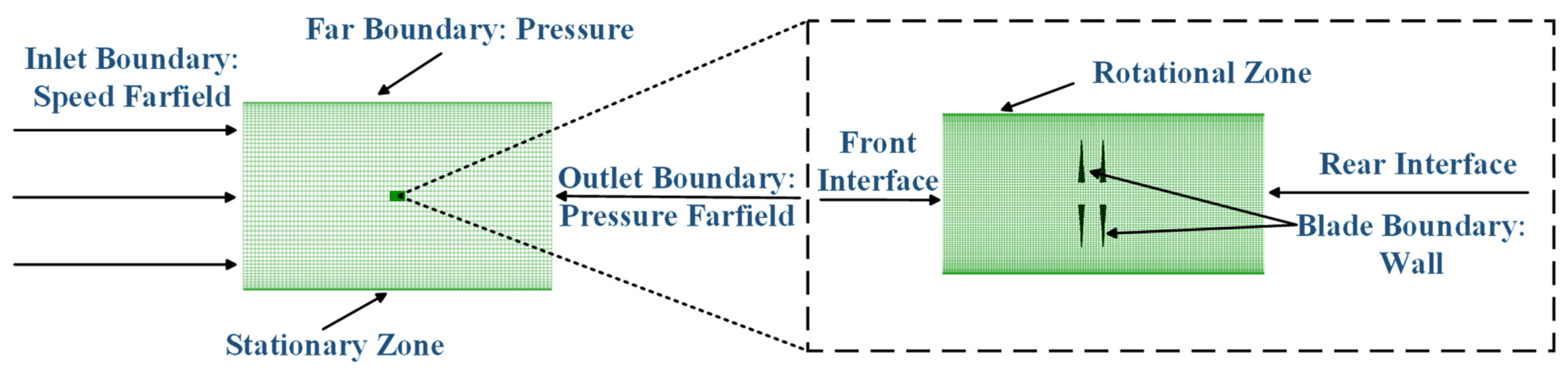
Regarding boundary conditions, to ensure the existence and uniqueness of the solutions to the governing equations, a velocity inlet or far-field inlet is prescribed to specify the incoming flow velocity and turbulence parameters. A pressure outlet boundary condition is applied at the downstream boundary to define the static pressure, while solid surfaces are treated as no-slip walls. The outer boundaries of the computational domain are placed sufficiently far from the propellers to minimize artificial boundary reflections and their influence on the internal flow field. The overall computational domain and boundary condition configuration for the contra-rotating propeller system are illustrated in Figure 1. All simulations were performed using the commercial CFD software ANSYS Fluent (v2024 R1) based on the finite volume method.

2.3. Validation of the Numerical Simulation Method

To verify the accuracy of the established numerical simulation approach in predicting the aerodynamic performance of contra-rotating propellers, wind tunnel test data from a self-developed contra-rotating propeller system by the research group are selected as the benchmark. The performance predictions obtained using both the quasi-steady (MRF) and unsteady (URANS) numerical methods are comparatively evaluated.
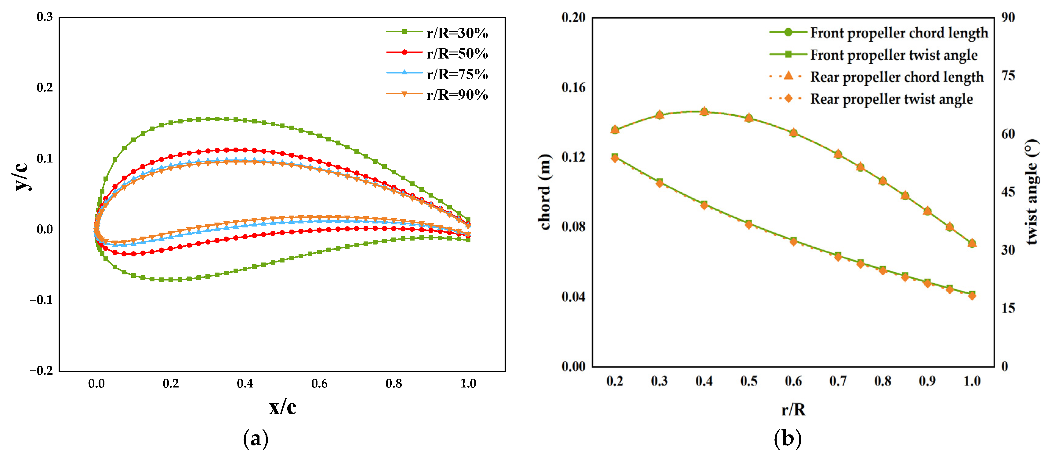
In the validation case, the front and rear propellers employ identical airfoil sections. Both propellers have a diameter of D = 1000 mm and a blade number of B = 2. The airfoil profiles, as well as the spanwise distributions of chord length and twist angle, are shown in Figure 2. In the numerical simulations, the geometric configuration is kept strictly consistent with the experimental setup, and calculations are conducted under the same inflow velocity and corresponding rotational speed conditions to ensure the comparability of the results.
In terms of mesh generation, a hybrid structured/unstructured grid is employed to discretize the flow field around the propellers. Separate meshes are generated for the front-rotor rotating domain, rear-rotor rotating domain, and stationary far-field domain, with coupling achieved through interface boundaries. The boundary-layer mesh is generated in Pointwise using the T-Rex method: the blade wall regions adopt structured prismatic layers grown in the wall-normal direction (e.g., 20 layers), while the main flow region uses isotropic tetrahedral elements to balance near-wall resolution with manageable overall mesh size.
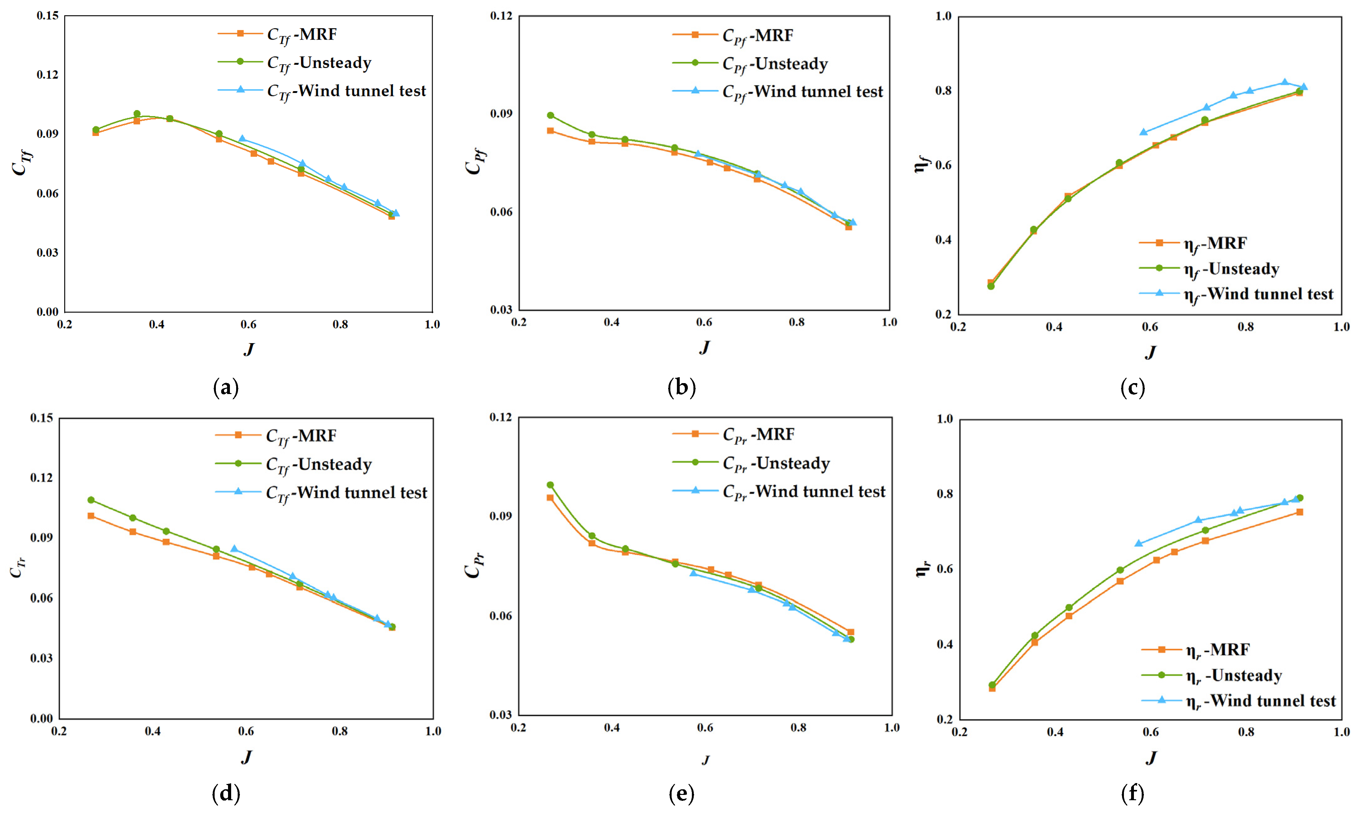
For the validation case, a representative operating condition at an altitude of 0.4 km with an inflow velocity of V = 10.56 m/s is selected. Different advance ratios J are achieved by varying the rotational speed, and the numerical results are compared with wind tunnel measurements. Figure 3 presents the comparison of the quasi-steady (MRF) and unsteady (URANS) simulation results with experimental data for the front and rear propellers’ thrust coefficient (CT), power coefficient (CP), and efficiency (η) under different J conditions. Overall, both numerical methods capture the basic trends of front and rear propeller aerodynamic performance as a function of advance ratio, in good agreement with the experimental data. Quantitatively, for the front propeller, the maximum relative errors of the quasi-steady method in CT, CP, and η are 6.56%, 4.61%, and 6.14%, respectively, while for the unsteady method, they are 3.69%, 2.31%, and 5.26%. For the rear propeller, the quasi-steady method yields maximum relative errors of 7.45%, 3.36%, and 8.40%, whereas the unsteady method achieves 4.35%, 1.95%, and 4.78%. The relatively larger errors for the rear propeller are primarily due to the significant influence of the front propeller wake’s induced velocity and vortex structures, resulting in more complex unsteady flow characteristics that place higher demands on numerical modeling and solution accuracy. Comparison of the two methods indicates that unsteady simulations provide slightly higher overall accuracy but at a substantially increased computational cost. The quasi-steady method strikes a better balance between accuracy and efficiency, making it more suitable for design-phase trend analysis and parameter studies, whereas the unsteady method is recommended for design-point verification and operating conditions with higher accuracy requirements.
In summary, through comparison with wind tunnel test data, the numerical simulation method established in this study can accurately predict the variations in thrust, power, and efficiency of the front and rear propellers under different advance ratio conditions. This provides a reliable computational foundation for the subsequent analysis of design variable effects and flow characteristics of high-altitude contra-rotating propellers.

3. Analysis of Aerodynamic Performance and Flow Field Characteristics of Contra-Rotating and Conventional Propellers

3.1. Comparative Analysis of Aerodynamic Performance

The aerodynamic simulations in this study are conducted under representative near-space conditions at an altitude of 20 km. The atmospheric properties are defined based on the International Standard Atmosphere (ISA) model. At this altitude, the air density, temperature, and static pressure are 0.0889 kg/m3, 216.65 K, and 5529.3 Pa, respectively. These parameters are specified as ambient atmospheric conditions and are used to define the fluid properties and reference state of the computational domain, thereby ensuring that the low-density characteristics of the near-space environment are properly represented.
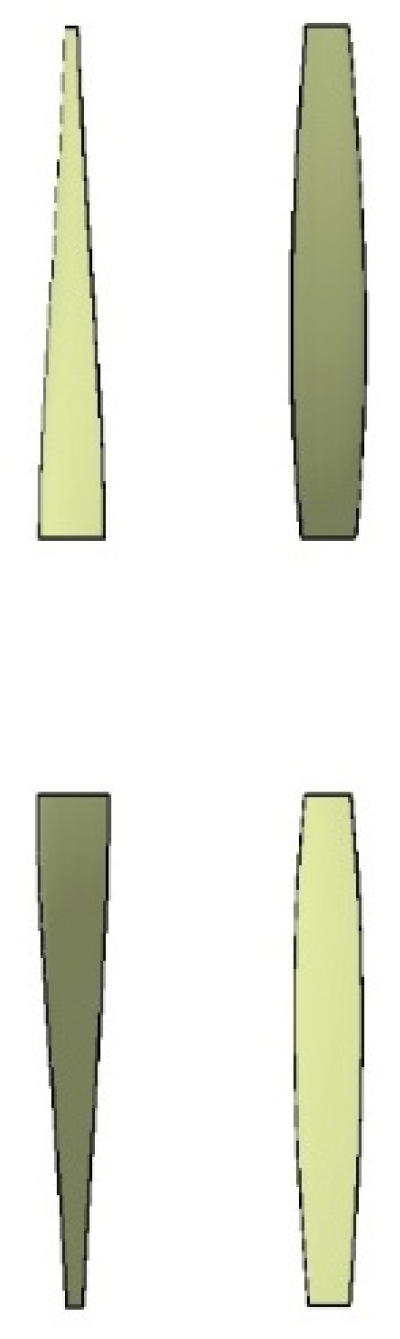
Aerodynamic performance analysis of conventional and contra-rotating propellers is conducted under a representative near-space condition at an altitude of 20 km with an inflow velocity of 20 m/s which represents the true freestream velocity under the specified atmospheric conditions. The contra-rotating propeller has a diameter of diameter (D) = 5.6 m and an inter-axial distance of S = 0.2 D. The front and rear rotors rotate at the same speed, and variations in the advance ratio are achieved by adjusting the propeller rotational speed. For comparison purposes, the front rotor of the contra-rotating propeller is treated as a conventional single propeller. The baseline configuration of the contra-rotating propeller is shown in Figure 4.
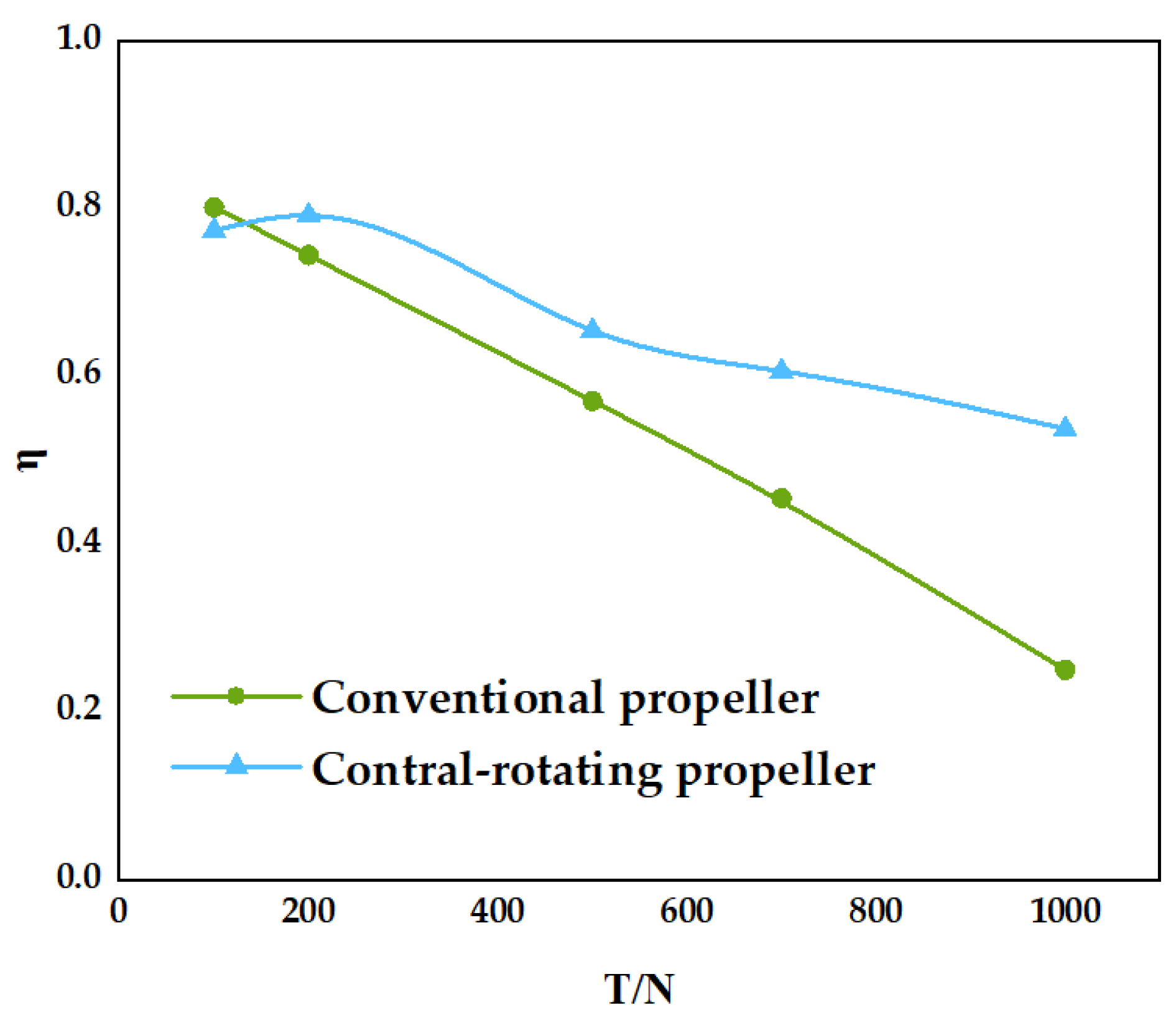
As shown in Figure 5 and Table 1, there are significant differences in performance between conventional and contra-rotating propellers. Under the same thrust output, the torque required by a conventional propeller is notably higher than that of a contra-rotating propeller. This difference arises primarily from the unique counter-rotating dual-propeller configuration of the contra-rotating system. The front and rear rotors rotate in opposite directions, causing their generated torques to partially cancel each other, thereby partially balancing the reaction torque acting on the airframe, which is beneficial for flight stability. However, the improvement in propulsive efficiency mainly arises from the recovery of rotational kinetic energy in the wake of the front rotor by the rear rotor.
In terms of propulsive efficiency, although both configurations can produce the same thrust, the contra-rotating propeller consistently achieves higher overall efficiency. For example, at a thrust of 200 N, the propulsive efficiency of the contra-rotating propeller is 79.24%, compared with 74.51% for the conventional propeller. When the thrust increases to 500 N, the contra-rotating propeller maintains an efficiency of 65.54%, while the conventional propeller drops to 57.16%. Although the efficiency of the contra-rotating propeller decreases slightly with increasing thrust, it remains higher than that of the conventional propeller across the entire thrust range. This efficiency advantage is primarily attributed to the synergistic interaction between the front and rear rotors. The contra-rotating propeller distributes aerodynamic loading more evenly between the two rotors, reducing the load each blade must carry. Simultaneously, the rear rotor recovers part of the rotational energy from the front rotor slipstream, decreases wake energy losses, and partially restores the circulation induced by the front rotor, thereby reducing overall energy consumption. As thrust demands further increase, the efficiency gap between the two configurations becomes more pronounced. For instance, at 1000 N thrust, the contra-rotating propeller maintains an efficiency of 53.82%, whereas the conventional propeller efficiency drops sharply to 25.12%. This indicates that under high-thrust conditions, contra-rotating propellers exhibit better aerodynamic stability and efficiency retention. It should be noted, however, that under conditions of high advance ratio and low thrust, the conventional propeller can achieve slightly higher efficiency than the contra-rotating propeller. This is mainly because, at high inflow speeds and low rotational speeds, the aerodynamic interactions between the front and rear rotors of the contra-rotating system become more complex, leading to increased vortex losses and induced drag, which slightly diminishes its efficiency advantage.

3.2. Analysis of Flow Field Characteristics

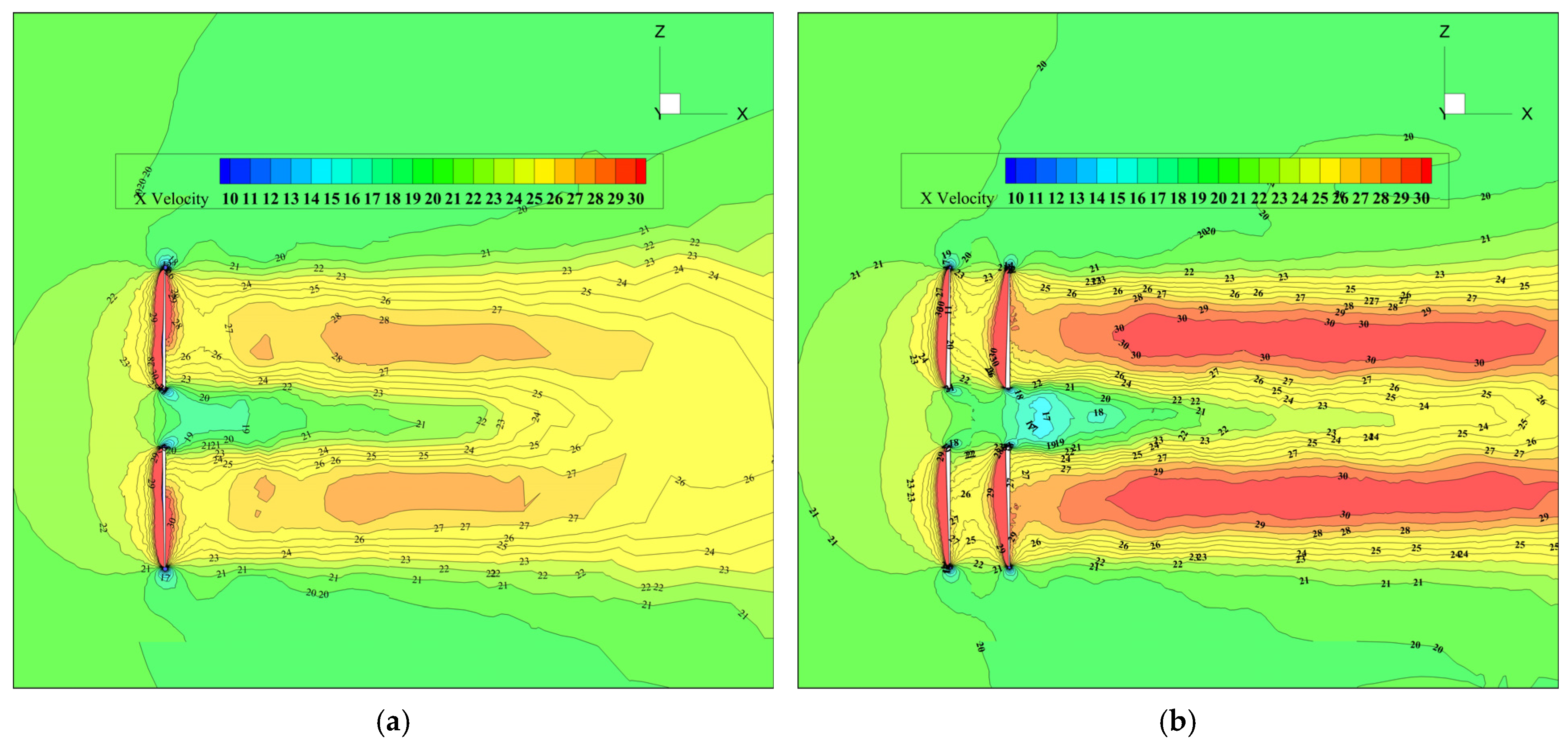
To investigate the mechanisms behind the efficiency improvement of contra-rotating propellers, a flow field analysis is conducted for both conventional and contra-rotating propellers under a thrust condition of 500 N.
Figure 6 presents the axial velocity distribution contours for the conventional and contra-rotating propellers at the same thrust level. For the conventional propeller, although the axial velocity in the downstream slipstream region is significantly higher than the freestream velocity, the high-speed region is mainly concentrated near the rotor disk and decays rapidly along the axial direction. Moreover, noticeable velocity non-uniformity exists within the slipstream, indicating that while the conventional propeller generates thrust, a substantial portion of non-axial flow remains in the wake, leading to energy losses. In contrast, the axial velocity distribution of the contra-rotating propeller exhibits marked differences. The overall axial velocity level in the downstream slipstream is significantly higher, the high-speed region extends further along the axial direction, and the velocity distribution across the slipstream is more uniform. This suggests that the rear rotor, operating in the front rotor’s wake, effectively suppresses non-axial flow components, concentrating more momentum in the axial direction and thereby improving energy utilization. Additionally, the continuity and stability of the slipstream core in the contra-rotating propeller are superior to those of the conventional propeller. The axial velocity contours are smoother, reflecting that inter-rotor interactions improve the downstream flow structure. Overall, these flow field characteristics indicate that, under the same thrust conditions, contra-rotating propellers achieve higher propulsive efficiency by enhancing axial momentum distribution in the wake and reducing flow losses.

4. Analysis of Design Variable Effects

4.1. Axial Distance

In the calculations, the flight altitude is set at 20 km with an incoming flow velocity of 20 m/s. The pitch angles and rotational speeds of the front and rear propellers are maintained identically, and the configuration of the contra-rotating propellers (CRPs) remains consistent with that described in Section 3.1. The aerodynamic performance of the CRP is evaluated by varying the axial spacing between the front and rear propellers. This spacing, denoted as S, is expressed as a ratio of the propeller diameter, with five specific values investigated: 0.10, 0.20, 0.30, 0.40, and 0.50. Furthermore, variations in the advance ratio are achieved by adjusting the rotational speed of the propellers.
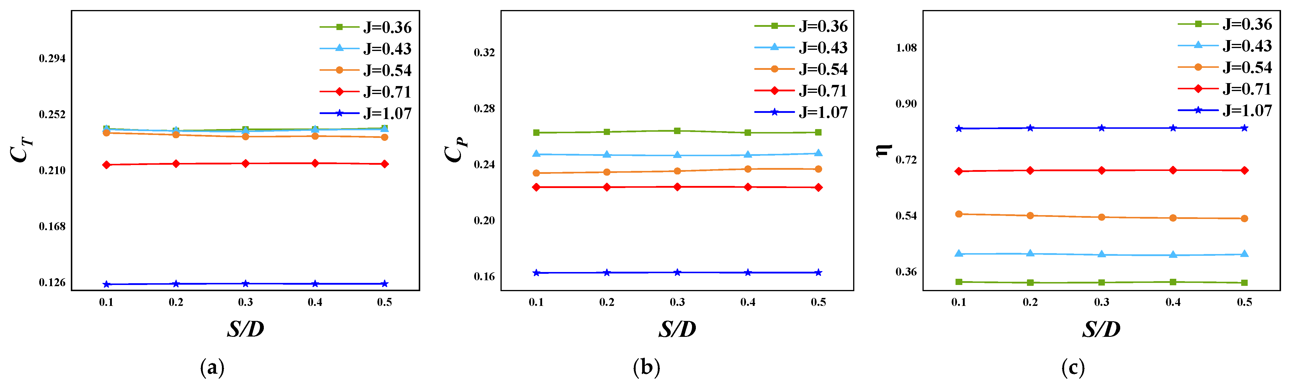
As shown in Figure 7, under near-space conditions at an altitude of 20 km, the effect of inter-axial distance on the aerodynamic performance of contra-rotating propellers is relatively limited within the investigated range of S/D = 0.10~0.50 and advance ratios J ≈ 0.36~1.07. Across different advance ratios, the thrust coefficient CT varies only slightly with spacing, with minor fluctuations observed near S/D ≈ 0.20~0.30. The power coefficient CP shows a weak increasing trend or remains nearly constant with increasing spacing, while propulsive efficiency η exhibits a slight decrease or remains stable, with this trend more pronounced under lower advance ratios. Overall, the changes are minimal. Quantitatively, the variation in propulsive efficiency is less than approximately 1%, while the variations in thrust coefficient and power coefficient remain within about 2% across the investigated conditions.
Overall, these results indicate that, within the present parameter range, inter-axial distance has a limited influence on aerodynamic performance. Therefore, in subsequent design optimization, spacing can be treated as an adjustable parameter under engineering constraints, with its selection primarily informed by structural layout, vibration/noise considerations, and safety clearances.
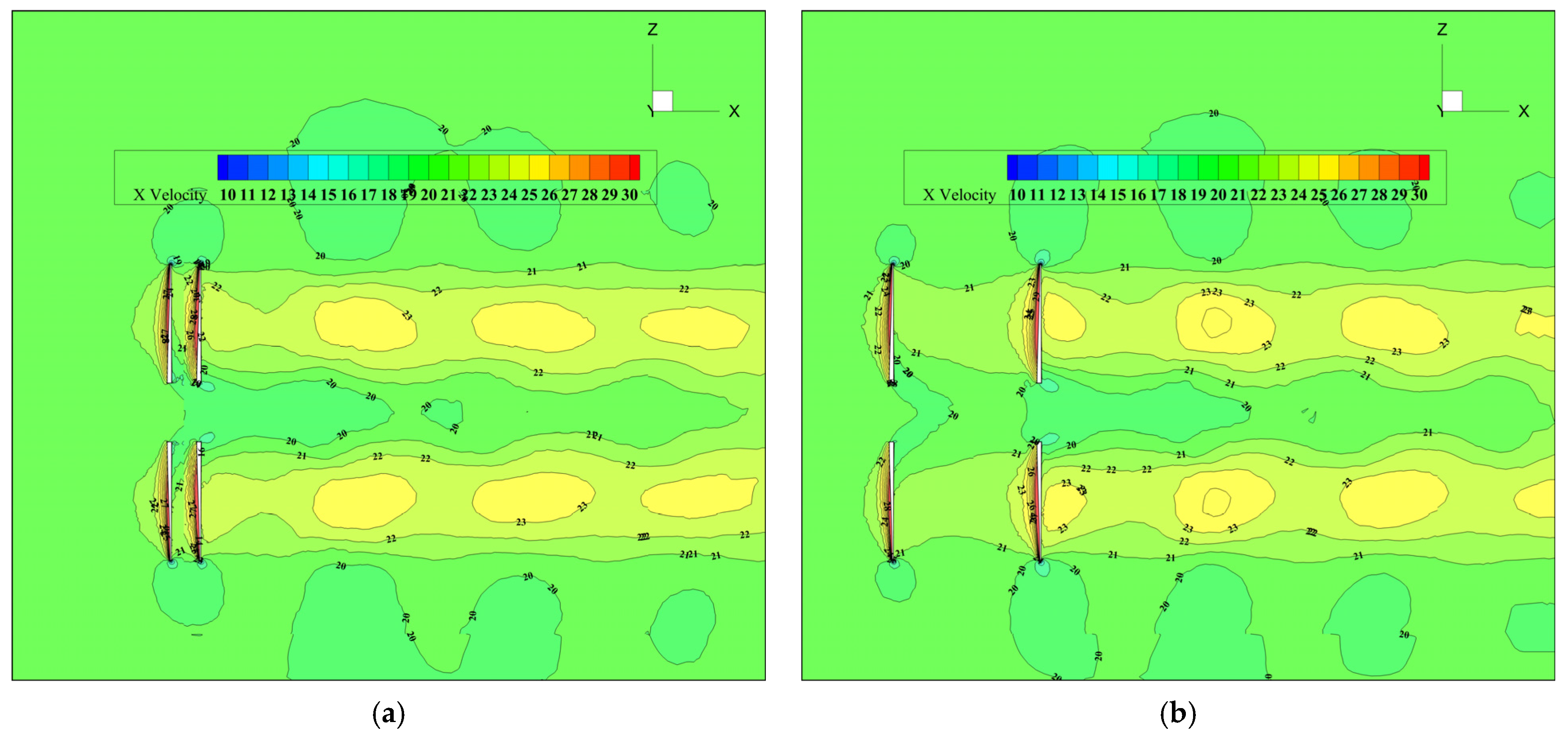
Under high-altitude conditions at 20 km and an advance ratio of J = 1.07, the axial velocity distributions of the contra-rotating propeller at different inter-axial distances are shown in Figure 8. As observed, when the spacing is small (S/D = 0.1), aerodynamic interference between the front and rear rotors is significant. The front rotor wake has not fully expanded before entering the rear rotor disk, resulting in a non-uniform inflow velocity distribution for the rear rotor. The slipstream core appears compact along the axial direction, with the high-speed region concentrated within a limited range immediately downstream of the rotor disk, and velocity decay along the axial direction is relatively rapid. As the spacing increases to S/D = 0.5, the front rotor wake has more room to develop before reaching the rear rotor. The axial velocity distribution becomes more uniform, inflow conditions for the rear rotor improve, and the slipstream core extends further downstream. The high-speed region also expands, leading to a more continuous and uniform axial velocity distribution overall. This indicates that increasing the inter-axial distance helps reduce direct aerodynamic interference between the rotors, stabilizing the front rotor wake and improving the rear rotor’s ability to utilize inflow momentum. It should be noted that under high-altitude, low-density, and high-advance-ratio conditions, while inter-axial distance affects slipstream strength and axial velocity distribution to some extent, the overall flow field structure remains largely unchanged. This suggests that spacing primarily influences aerodynamic performance by modulating the degree of rotor interaction and the wake development process.

4.2. Pitch Angle

In this subsection, the contra-rotating propeller configuration described in Section 3.1 is adopted as the baseline model, with an inter-axial distance of S/D = 0.2. The inflow velocity is set to 20 m/s, and the front and rear rotors operate at identical rotational speeds. The pitch angles of the front and rear rotors are varied to evaluate their effects on aerodynamic performance. The notation f0_r1 denotes the configuration in which the front rotor pitch angle remains unchanged relative to the baseline, while the rear rotor pitch angle is increased by 1°.

4.2.1. Variation of Rear Rotor Pitch with Fixed Front Rotor Pitch

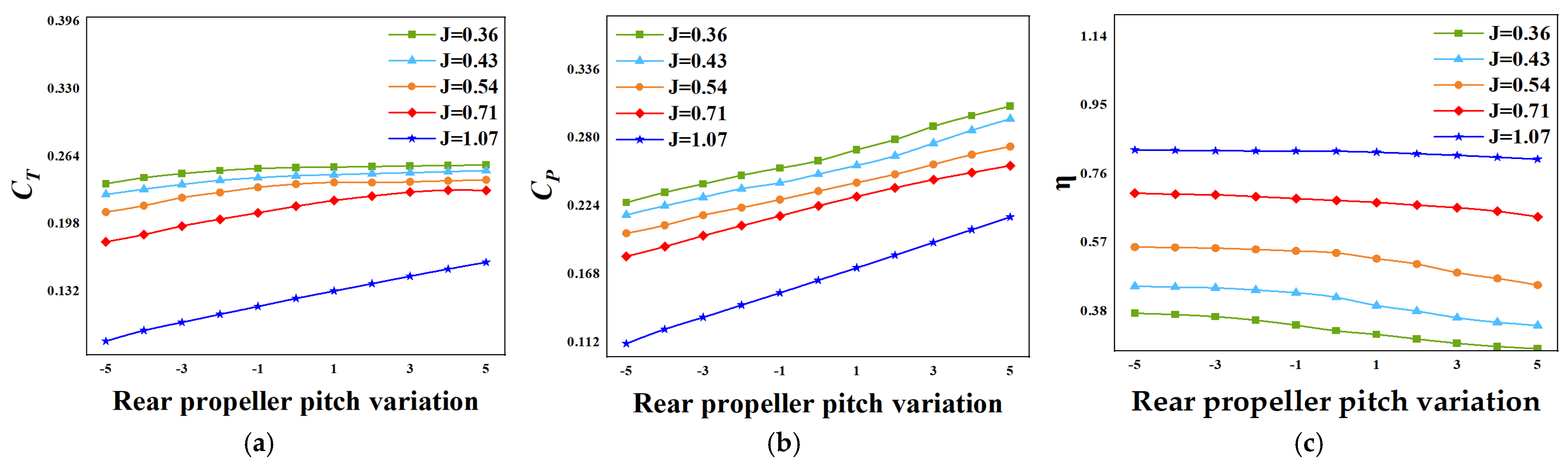
As shown in Figure 9, under near-space conditions, increasing the rear rotor pitch angle leads to a monotonic increase in the thrust coefficient CT across all advance ratios. The power coefficient CP increases simultaneously, while the propulsive efficiency η exhibits an overall decreasing trend. This indicates that a larger rear rotor pitch angle enhances thrust output but at the expense of increased power consumption. Further analysis under different advance ratios reveals that, at higher advance ratios, CT responds more sensitively to pitch angle variations, whereas the growth of CP is relatively moderate, resulting in a smaller reduction in efficiency. In contrast, under lower advance ratio conditions, the increase in CP becomes dominant, leading to a more pronounced decrease in propulsive efficiency with increasing pitch angle. This suggests that, under high rotational speed conditions, increasing the pitch angle has a more significant impact on power demand.
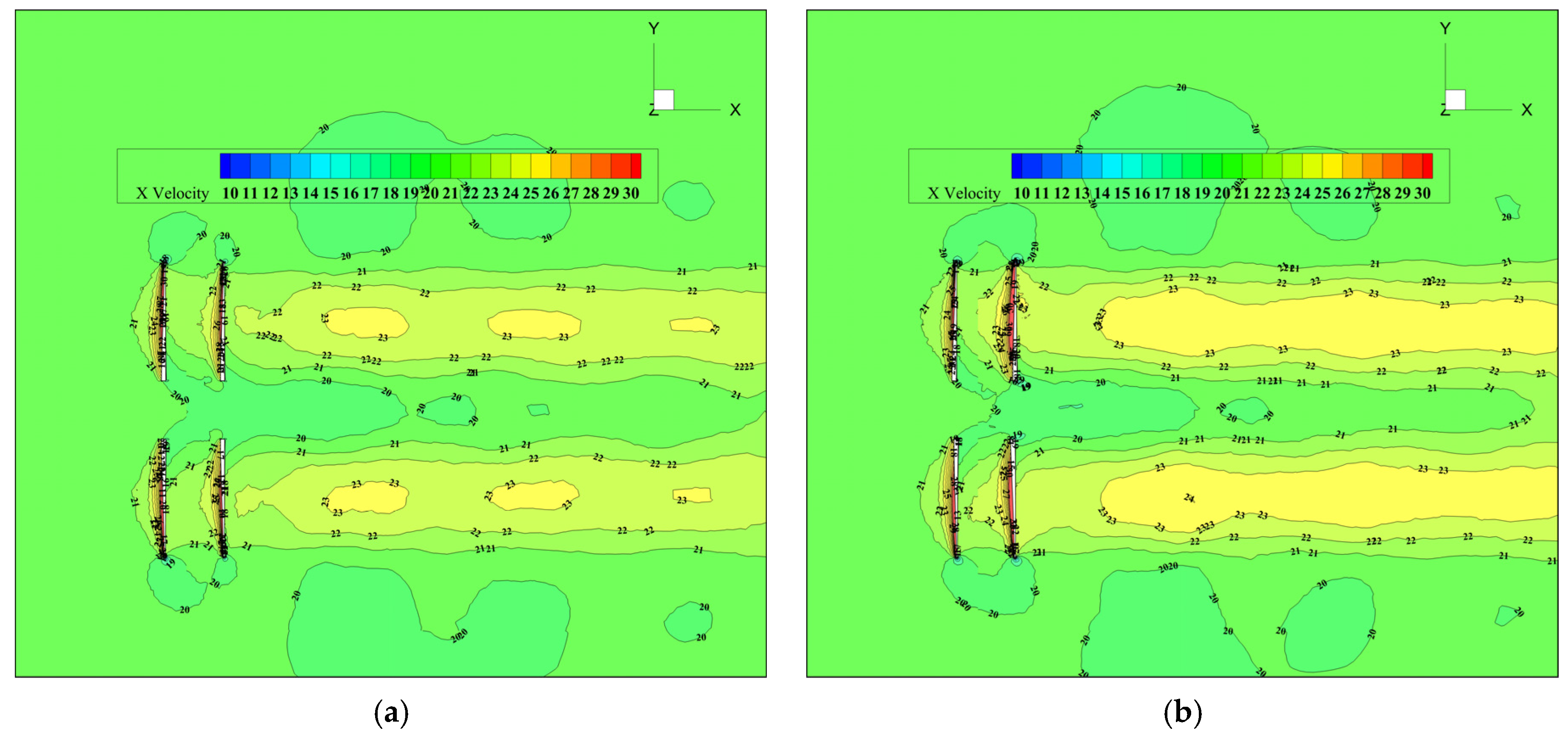
Under high-altitude conditions at 20 km with an advance ratio of J = 1.07, the influence of rear rotor pitch angle variation on the flow field of the contra-rotating propeller is primarily reflected in the axial velocity distribution within the downstream wake. As shown in Figure 10, when the rear rotor pitch angle increases from −2° to +2°, the overall axial velocity level in the slipstream region increases, the high-speed core region expands slightly, and the downstream axial extension becomes longer, indicating an enhanced axial acceleration effect of the rear rotor on the incoming flow. Meanwhile, the slipstream boundary and overall flow structure remain largely unchanged, with no significant velocity distortion or strong non-uniform distribution observed. This suggests that under high-altitude, low-density, and high-advance-ratio conditions, variations in rear rotor pitch angle primarily affect flow intensity rather than the fundamental flow field structure. These results indicate that increasing the rear rotor pitch angle can moderately enhance the axial momentum level in the downstream wake, while its influence on the overall flow structure remains relatively limited.

4.2.2. Variation of Front Rotor Pitch with Fixed Rear Rotor Pitch

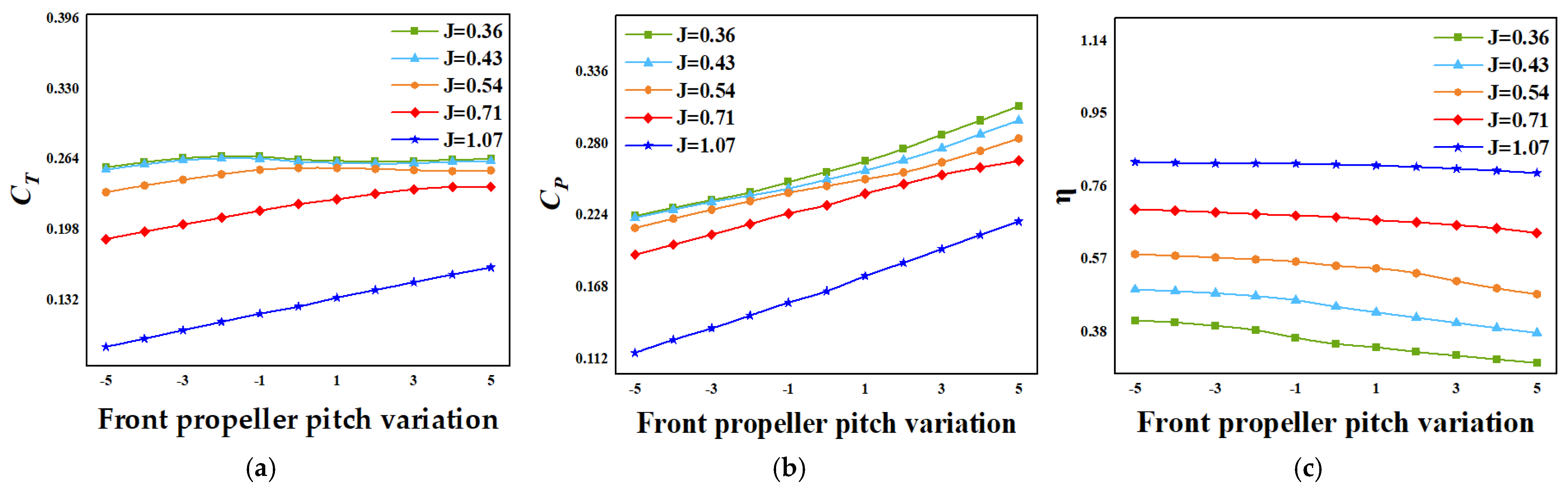
As shown in Figure 11, under near-space conditions, the influence of varying the front blade pitch on the aerodynamic performance of the contra-rotating propeller exhibits a consistent overall trend, although significant differences are observed under different advance ratio conditions. In general, as the front blade pitch increases, the power coefficient CP shows a steady upward trend across all advance ratios, indicating a continuous increase in the power demand of the front propeller. In contrast, the thrust coefficient CT exhibits a strong dependence on the operating condition: at high advance ratios, CT increases monotonically with blade pitch, whereas at low advance ratios, CT initially increases and then tends to plateau. Since the growth of CP is generally more consistent and pronounced, the overall propulsive efficiency η decreases with increasing front blade pitch, indicating that enhancing thrust by increasing the front blade pitch is generally accompanied by a reduction in propulsive efficiency.
From the above analysis, it can be concluded that the front blade pitch consistently exhibits the aerodynamic characteristics of “monotonic power increase, thrust constrained by operating conditions, and overall efficiency decrease” across different flight altitudes, with the magnitude of its influence slightly diminishing at higher altitudes. Therefore, in the design and optimization of contra-rotating propeller parameters, the front blade pitch should be selected judiciously, considering both flight altitude and advance ratio, to achieve a balance between thrust requirements and efficiency loss.
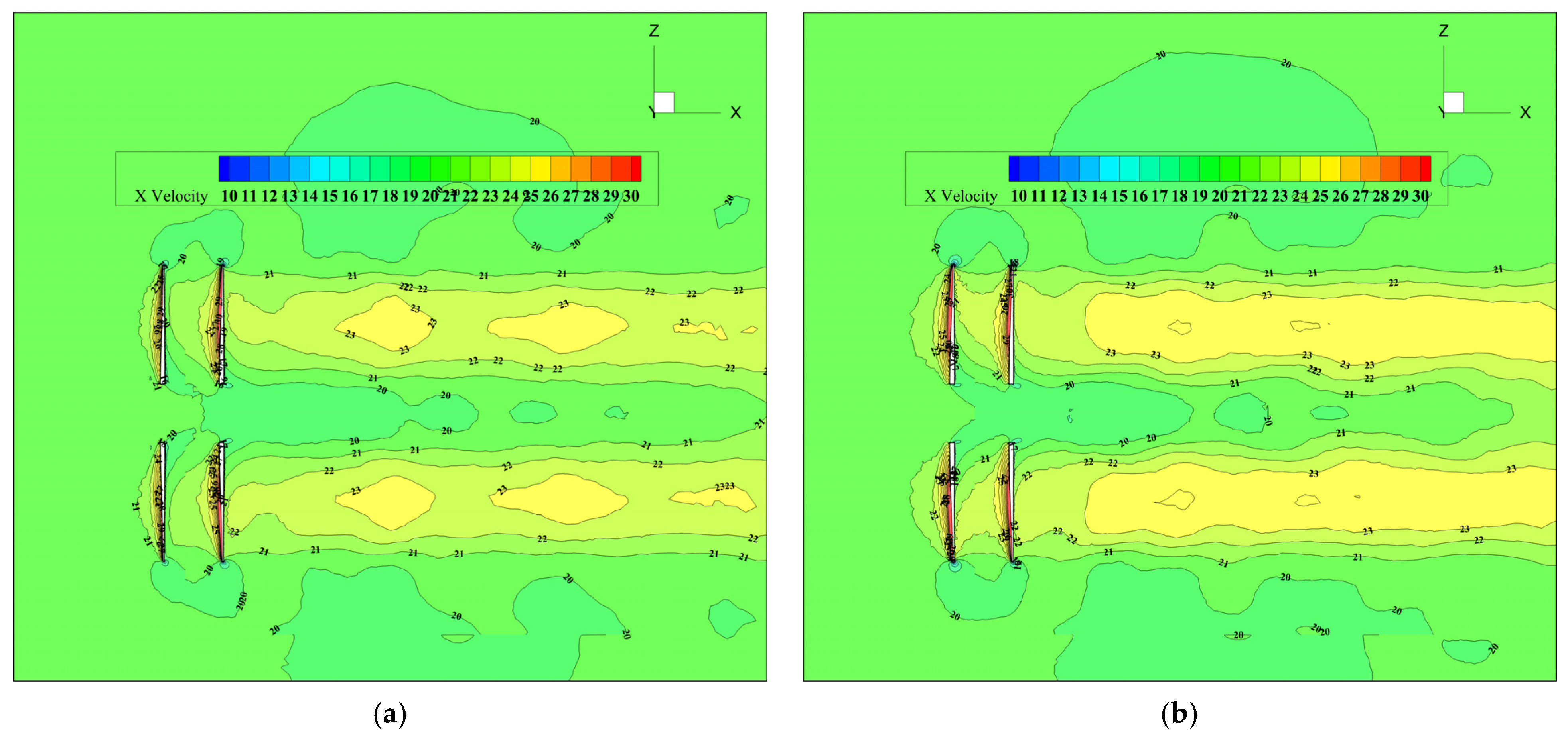
Under the 20 km altitude condition and an advance ratio of J = 1.07, the axial velocity distributions corresponding to different front blade pitch angles are shown in Figure 12. As the front blade pitch angle increases from −2° to +2°, the axial acceleration imparted by the front propeller to the incoming flow is enhanced. The downstream slipstream exhibits an overall increase in axial velocity, and the high-speed core region extends further along the axial direction, indicating that the front propeller’s contribution to the axial momentum of the flow is strengthened. At smaller pitch angles, the axial velocity distribution downstream of the front propeller is relatively uniform, with the high-speed region mainly confined to a limited area immediately behind the propeller disk, and the axial velocity decays rapidly downstream. As the front blade pitch angle increases, the axial velocity within the slipstream core rises, and the downstream momentum retention improves, providing the rear propeller with higher-quality axial inflow conditions. It is worth noting that, under the thin-air, high-advance-ratio conditions of the near-space environment, the overall slipstream structure remains relatively stable even as the front blade pitch angle changes. No significant velocity distortions or pronounced non-uniformities are observed, indicating that variations in the front blade pitch primarily affect the magnitude of axial velocity and momentum levels, while the fundamental spatial structure of the slipstream remains largely unchanged. Overall, at 20 km altitude and high advance ratio, increasing the front blade pitch angle can moderately enhance the axial acceleration downstream of the propeller and improve slipstream momentum levels, while exerting limited influence on the overall flow field structure.

4.3. Front and Rear Propeller Rotational Speeds

4.3.1. Variation of Rear Rotor Speed with Fixed Front Rotor Speed

In this subsection, the co-rotating propeller configuration from Section 3.1 is used as the baseline, with an inter-propeller spacing of S/D = 0.2. The flight altitude is 20 km and the freestream velocity is 20 m/s. The pitch angles of the front and rear propellers are kept identical, while the propeller rotational speeds are varied to study their effects on aerodynamic performance. Here, the speed ratio is defined as the ratio of the front propeller speed to the rear propeller speed.
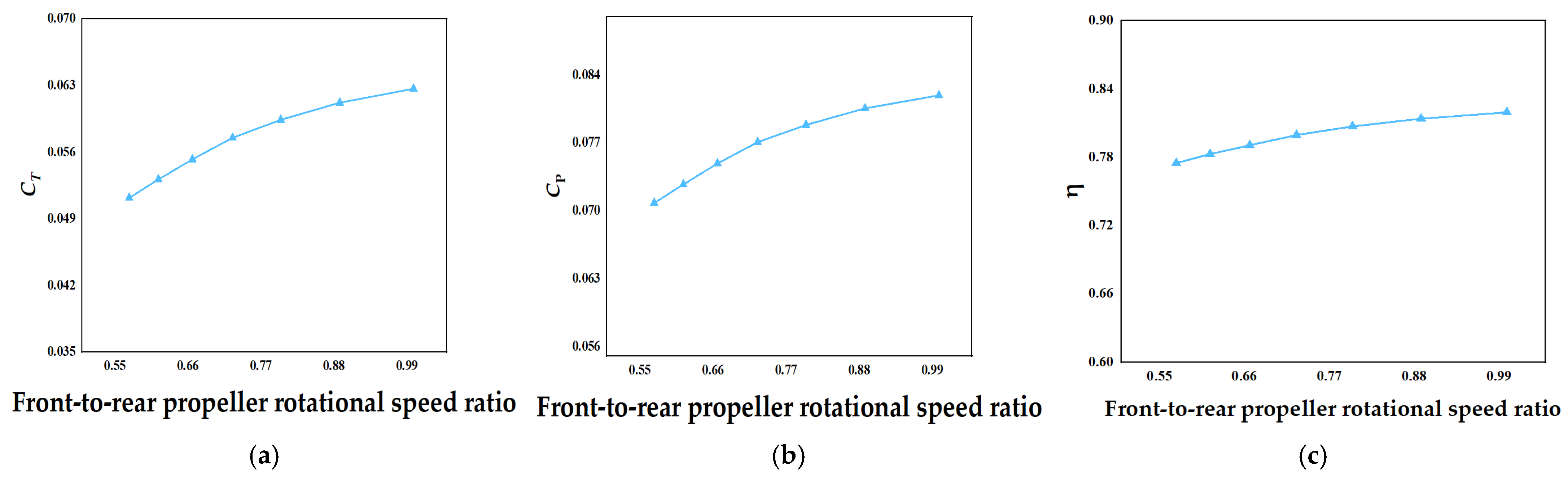
Under the condition of a fixed front propeller speed, the influence of the rear propeller rotational speed on the aerodynamic performance of the co-rotating propeller system was systematically analyzed, as summarized in Table 2. The results indicate that, in near-space conditions, increasing the rear propeller speed leads to a steady increase in the total thrust coefficient. This suggests that, with the front propeller operating at a constant state, a higher rear propeller speed can more effectively extract and recover the rotational energy from the front propeller slipstream, thereby enhancing the overall thrust output of the system. Simultaneously, the power coefficient also rises continuously with increasing rear propeller speed, indicating that higher rear propeller speeds directly result in greater power demands and significantly increase the system’s energy input requirements.
Under the condition of fixed front propeller rotational speed, the front-to-rear propeller speed ratio was adjusted by varying the rear propeller speed. The variation of the front propeller aerodynamic performance with the speed ratio is shown in Figure 13. It can be observed that, at an altitude of 20 km, as the front-to-rear speed ratio increases, the front propeller thrust coefficient CT gradually rises, the power coefficient CP increases correspondingly, and the propulsive efficiency η exhibits a slight improvement. These results indicate that when the rear propeller speed changes, leading to an adjustment in the inter-stage matching, the front propeller’s load level and energy input increase, accompanied by a modest enhancement in efficiency. The primary mechanism is that the variation in rear propeller speed alters the degree of attenuation of the wake’s rotational components, thereby influencing the inflow conditions and induced environment encountered by the front propeller. When the rear propeller speed increases, its suppression of the rotational component in the front propeller wake is strengthened, resulting in a higher axial velocity component and reduced non-axial disturbances in the front propeller inflow, which improves its aerodynamic operating conditions and leads to an increase in CT. Meanwhile, although CP also rises, its growth rate is relatively lower, resulting in a slight improvement in the front propeller propulsive efficiency η.

4.3.2. Variation of Front Rotor Speed with Fixed Rear Rotor Speed

Under this condition, the front propeller speed is varied while the rear propeller speed is kept constant, and the aerodynamic performance of the contra-rotating propeller system is evaluated. The calculation conditions are listed in Table 3.
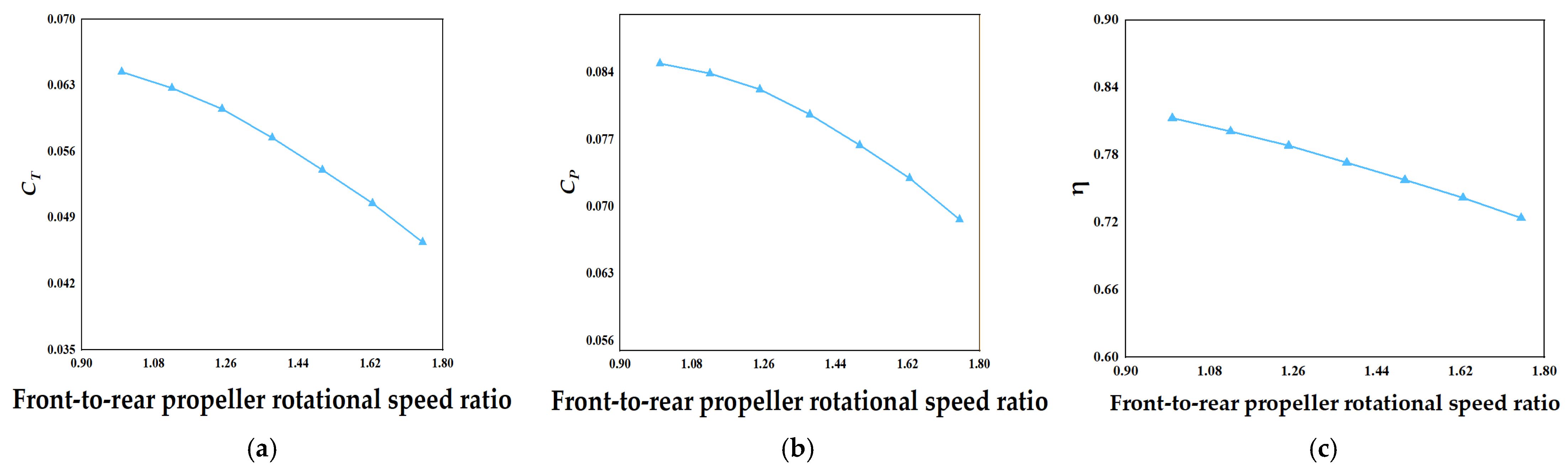
As the front propeller speed increases, both the thrust and power levels of the front propeller itself and the overall contra-rotating system inevitably rise, while the propulsive efficiency correspondingly decreases. Therefore, in this scenario, the focus is on the influence of front propeller speed variations on the rear propeller’s aerodynamic performance. As shown in Figure 14, at an altitude of 20 km, the rear propeller thrust coefficient (CT), power coefficient (CP), and propulsive efficiency (η) all exhibit a continuous decreasing trend with increasing front-to-rear speed ratio. This indicates that, when the front propeller speed increases while the rear propeller speed remains constant, the rear propeller’s thrust contribution and power absorption capability are simultaneously reduced. The underlying mechanism is that an increased front propeller speed enhances the velocity magnitude and rotational component of the front propeller’s wake, thereby altering the inflow direction and velocity distribution encountered by the rear propeller. With the rear propeller speed unchanged, the effective angle of attack and load distribution relative to the incoming flow are modified, reducing its efficiency in converting incoming flow energy. Consequently, both CT and CP of the rear propeller decrease, which further leads to a decline in the propulsive efficiency η.

5. Conclusions

This study systematically investigated the aerodynamic advantages of counter-rotating propellers for high-altitude UAV propulsion applications under near-space operating conditions and analyzed the effects of key design variables on their aerodynamic characteristics. The main conclusions are summarized as follows:
  • Under the same thrust output, conventional propellers require significantly higher torque than counter-rotating propellers, which highlights the inherent advantage of the counter-rotating configuration in achieving effective torque cancellation through opposite rotational directions. This feature effectively reduces the torque demand on the airframe for attitude control and alleviates the workload of the flight control system. Meanwhile, counter-rotating propellers maintain higher propulsive efficiency over a wide thrust range: for example, at 200 N thrust, efficiency reaches 79.24% (conventional propeller: 74.51%); at 500 N, 65.54% (conventional: 57.16%); and at 1000 N, the counter-rotating propeller still achieves 53.82%, whereas the conventional propeller drops to 25.12%. This indicates that counter-rotating propellers exhibit superior efficiency retention and performance stability under high-thrust conditions.
  • Within the range of S/D = 0.10–0.50, the thrust coefficient (CT) varies only slightly with propeller spacing, with minor fluctuations around S/D ≈ 0.20–0.30; the power coefficient (CP) shows a weak upward trend or remains nearly constant; and the propulsive efficiency (η) exhibits a slight decrease or remains approximately stable. Flow field comparisons further reveal that increasing the propeller spacing allows the front propeller wake to develop more fully before entering the rear propeller, resulting in a more uniform inflow and an axially extended slipstream core for the rear propeller. However, under near-space conditions with low air density and high advance ratio, these improvements primarily affect wake development and interference levels rather than induce a significant performance leap. Therefore, propeller spacing in future designs can be selected based on structural compactness, safety clearance requirements, and overall integration constraints of high-altitude UAV platforms.
  • At 20 km altitude, increasing either the front or rear propeller pitch angle generally results in higher CT, increased CP, and a decrease in η. For the rear propeller, CT increases monotonically with pitch angle, indicating a direct contribution to overall thrust. However, under low advance ratio (high-speed) conditions, the increase in power dominates, leading to a more pronounced drop in efficiency. Flow field analysis shows that pitch angle changes mainly affect the axial velocity level and high-speed core region of the slipstream, with limited influence on the overall flow structure, reflecting the characteristic of “intensity modulation dominates, structural alteration secondary.”
  • When the front propeller speed is fixed, and the rear propeller speed is increased, both the total thrust coefficient and power coefficient rise, while the overall efficiency decreases with the speed ratio. Meanwhile, the front propeller CT and CP increase slightly with speed ratio, and efficiency improves modestly, indicating that the increased rear propeller speed enhances the attenuation of rotational components in the front propeller wake, improving the induced flow environment and effective inflow for the front propeller. Conversely, when the rear propeller speed is fixed, and the front propeller speed is increased, the rear propeller CT, CP, and efficiency all decrease continuously with increasing speed ratio. This demonstrates that increasing the front propeller speed strengthens the wake’s velocity and rotational components, altering the effective inflow angle and load distribution of the rear propeller, thereby reducing its energy conversion efficiency and weakening its thrust contribution. These findings emphasize the critical role of “speed matching/inter-stage matching” in counter-rotating propeller design.
Overall, the present findings clarify the aerodynamic interaction mechanisms of contra-rotating propellers under low-density near-space conditions and identify critical design parameters for performance improvement. The demonstrated advantages in efficiency retention, torque mitigation, and speed matching provide valuable guidance for the propulsion system design and optimization of high-altitude long-endurance UAVs. These insights contribute to enhancing flight endurance, mission capability, and overall system performance of near-space unmanned platforms.

Author Contributions

Conceptualization, W.C. and X.J.; methodology, W.C., X.J. and Z.W.; validation, formal analysis and investigation, W.C., X.J., Z.W. and S.W.; writing—original draft preparation, W.C.; writing—review and editing, W.C. and X.J.; supervision, Z.W. and S.W.; project administration, X.J., Z.W. and S.W. All authors have read and agreed to the published version of the manuscript.

Funding

This research received no external funding.

Data Availability Statement

The data presented in this study are available on request from the corresponding author.

Conflicts of Interest

The authors declare no conflicts of interest.

References

  1. d’Oliveira, F.A.; Melo, F.C.L.d.; Devezas, T.C. High-altitude platforms-Present situation and technology trends. J. Aerosp. Technol. Manag. 2016, 8, 249–262. [Google Scholar] [CrossRef]
  2. Dumas, A.; Trancossi, M.; Madonia, M.; Giuliani, I. Multibody Advanced Airship for Transport; SAE Technical Paper 2011-01-2550; SAE International: Warrendale, PA, USA, 2011. [Google Scholar]
  3. Jamison, L.; Sommers, G.; Porche, I. High-Altitude Airships for the Future Force Army; Rand Corporation: Santa Monica, CA, USA, 2005. [Google Scholar]
  4. Colozza, A.; Dolce, J. Initial Feasibility Assessment of a High Altitude Long Endurance Airship; NASA/TM-2003-212724; NASA: Washington, DC, USA, 2003.
  5. Dolce, J.L.; Collozza, A. High-Altitude, Long-Endurance Airships for Coastal Surveillance; NASA/TM-2005-213809; NASA: Washington, DC, USA, 2005.
  6. Young, M.; Keith, S.; Pancotti, A. An overview of advanced concepts for near space systems. In Proceedings of the 45th AIAA/ASME/SAE/ASEE Joint Propulsion Conference & Exhibit, Denver, CO, USA, 2–5 August 2009; American Institute of Aeronautics and Astronautics: Reston, VA, USA, 2009; p. 4805. [Google Scholar]
  7. Du, M.; Chen, P.; Li, G.; Zhou, B. Propeller technology of near-space low-speed vehicles. Aerodyn. Missile J. 2011, 7, 15–19+28. (In Chinese) [Google Scholar] [CrossRef]
  8. Huang, W.; Li, Y.; Zhou, S.; Zhang, T. Military applications of modern aerostats. Sci. Technol. Rev. 2017, 35, 20–27. (In Chinese) [Google Scholar]
  9. Hager, R.D. Advanced Turboprop Project; Scientific and Technical Information Division, National Aeronautics and Space Administration (NASA): Washington, DC, USA, 1988.
  10. Lesieutre, D.J.; Sullivan, J.P. The Analysis of Counter-Rotating Propeller Systems; SAE Technical Paper 850869; SAE International: Warrendale, PA, USA, 1985; pp. 564–575. [Google Scholar]
  11. Biermann, D.; Gray, W. Wind-Tunnel Tests of Eight-Blade Single- and Dual-Rotating Propellers in the Tractor Position; National Advisory Committee for Aeronautics (NACA): Washington, DC, USA, 1941. [Google Scholar]
  12. Hughes, C.; Gazzaniga, J. Summary of low-speed wind tunnel results of several high-speed counterrotation propeller configurations. In Proceedings of the 24th Joint Propulsion Conference, Boston, MA, USA, 11–13 July 1988; American Institute of Aeronautics and Astronautics: Reston, VA, USA, 1988; p. 3149. [Google Scholar]
  13. De Giorgi, M.G.; Donateo, T.; Ficarella, A.; Fontanarosa, D.; Morabito, A.E.; Scalinci, L. Numerical investigation of the performance of contra-rotating propellers for a remotely piloted aerial vehicle. Energy Procedia 2017, 126, 1011–1018. [Google Scholar] [CrossRef]
  14. Zhang, Y.; Wang, X.; Ma, Y. Study on propulsion performance of contra-rotating propellers for stratospheric airship. J. Dalian Univ. Technol. 2020, 60, 233–240. (In Chinese) [Google Scholar]
  15. Qiao, N.; Ma, T.; Fu, J.; Zhang, L.; Wang, X.; Xue, P. Rapid blade shape optimization for contra-rotating propellers for eVTOL aircraft considering the aerodynamic interference. Aerospace 2023, 10, 54. [Google Scholar] [CrossRef]
  16. Rajagopalan, R.G. Three dimensional analysis of a rotor in forward flight. J. Am. Helicopter Soc. 1993, 38, 14–25. [Google Scholar] [CrossRef]
  17. Zori, L.A.J.; Rajagopalan, R.G. Navier—Stokes Calculations of Rotor—Airframe Interaction in Forward Flight. J. Am. Helicopter Soc. 1995, 40, 57–67. [Google Scholar] [CrossRef]
Figure 1. Boundary condition configuration for the contra-rotating propeller system.
Drones 10 00249 g001
Figure 2. Airfoil profiles and spanwise chord–twist distributions of the contra-rotating propellers: (a) Propeller airfoil profiles; (b) Spanwise chord and twist angle distributions of the contra-rotating propellers.
Drones 10 00249 g002
Figure 3. Validation of the contra-rotating propeller numerical model: (a) Front propeller CT versus advance ratio; (b) Front propeller CP versus advance ratio; (c) Front propeller η versus advance ratio; (d) Rear propeller CT versus advance ratio; (e) Rear propeller CP versus advance ratio; (f) Rear propeller η versus advance ratio.
Drones 10 00249 g003
Figure 4. Baseline configuration of the contra-rotating propeller.
Drones 10 00249 g004
Figure 5. Comparison of propulsive efficiency between conventional and contra-rotating propellers.
Drones 10 00249 g005
Figure 6. Flow field analysis of conventional and contra-rotating propellers: (a) axial velocity contours of conventional propeller; (b) axial velocity contours of contra-rotating propeller.
Drones 10 00249 g006
Figure 7. Comparison of aerodynamic performance of contra-rotating propellers with different axial distances at 20 km altitude: (a) variation of thrust coefficient with axial distance; (b) variation of power coefficient with axial distance; (c) variation of propulsive efficiency with axial distance.
Drones 10 00249 g007
Figure 8. Axial velocity contours of the contra-rotating propeller with different axial distances at 20 km altitude (J = 1.07): (a) axial distance S/D = 0.1; (b) axial distance S/D = 0.5.
Drones 10 00249 g008
Figure 9. Effect of rear propeller pitch angle on the aerodynamic performance of the contra-rotating propeller at 20 km altitude: (a) variation of thrust coefficient with rear rotor pitch angle for the contra-rotating propeller; (b) variation of power coefficient with rear rotor pitch angle for the contra-rotating propeller; (c) variation of propulsive efficiency with rear rotor pitch angle for the contra-rotating propeller.
Drones 10 00249 g009
Figure 10. Axial velocity contours of the contra-rotating propeller with different pitch angles at 20 km altitude (J = 1.07): (a) rear rotor pitch angle change of −2°; (b) rear rotor pitch angle change of 2°.
Drones 10 00249 g010
Figure 11. Effect of front propeller pitch angle on the aerodynamic performance of the contra-rotating propeller at 20 km altitude: (a) variation of thrust coefficient of the contra-rotating propeller with front blade pitch angle; (b) variation of power coefficient of the contra-rotating propeller with front blade pitch angle; (c) variation of propulsive efficiency of the contra-rotating propeller with front blade pitch angle.
Drones 10 00249 g011
Figure 12. Axial velocity contours of the contra-rotating propeller with different pitch angles at 20 km altitude (J = 1.07): (a) front propeller pitch angle −2°; (b) front propeller pitch angle 2°.
Drones 10 00249 g012
Figure 13. Effects of rotational speed ratio on the aerodynamic performance of the front propeller at 20 km altitude: (a) variation of front propeller CT with the front-to-rear speed ratio; (b) variation of front propeller CP with the front-to-rear speed ratio; (c) variation of front propeller propulsive efficiency η with the front-to-rear speed ratio.
Drones 10 00249 g013
Figure 14. Effects of rotational speed ratio on the aerodynamic performance of the rear propeller at 20 km altitude: (a) variation of rear propeller thrust coefficient (CT) with propeller speed ratio; (b) variation of rear propeller power coefficient (CP) with propeller speed ratio; (c) variation of rear propeller propulsive efficiency (η) with propeller speed ratio.
Drones 10 00249 g014
Table 1. Comparative aerodynamic performance of contra-rotating and conventional propellers.
Propeller TypeJT/NQ/(N·m)η/%
Contra-Rotating0.87100.00−6.5377.43
Conventional0.76100.0074.3180.24
Contra-Rotating0.79200.001.3479.24
Conventional0.67200.00151.8474.51
Contra-Rotating0.67500.0020.7365.54
Conventional0.49500.00391.0657.16
Contra-Rotating0.61700.0044.15460.69
Conventional0.40700.00552.6445.56
Contra-Rotating0.541000.0070.5053.82
Conventional0.291000.00796.4625.12
Table 2. Computational conditions with fixed front propeller speed and varying rear propeller speed at 20 km altitude.
Calculation ConditionFront/Rear Propeller Speed RatioPropeller TypeV (m/s)r/minCTCPηOverall
Efficiency
11.000Front Propeller202000.06260.081981.95%81.61%
Rear Propeller202000.06440.084981.29%
20.889Front Propeller202000.06120.080681.38%79.69%
Rear Propeller202250.08240.099778.73%
30.800Front Propeller202000.05940.078980.71%77.07%
Rear Propeller202500.09610.108875.72%
40.727Front Propeller202000.05750.077179.95%74.10%
Rear Propeller202750.10640.114372.58%
50.667Front Propeller202000.05520.074979.05%71.05%
Rear Propeller203000.11430.117469.54%
60.615Front Propeller202000.05310.072778.28%68.03%
Rear Propeller203250.120.118966.56%
70.571Front Propeller202000.05120.070877.49%64.98%
Rear Propeller203500.12370.119163.59%
Table 3. Computational cases with constant rear propeller speed and varying front propeller speed at 20 km altitude.
Calculation ConditionFront/Rear Propeller Speed RatioPropeller TypeV (m/s)r/minCTCPηOverall
Efficiency
11.000Front Propeller202000.06260.081981.95%81.61%
Rear Propeller202000.06440.084981.29%
21.125Front Propeller202250.08040.096479.47%79.71%
Rear Propeller202000.06270.083980.10%
31.250Front Propeller202500.09380.105276.44%77.13%
Rear Propeller202000.06050.082278.84%
41.375Front Propeller202750.1040.110673.31%74.18%
Rear Propeller202000.05750.079677.32%
51.500Front Propeller203000.11170.113670.19%71.12%
Rear Propeller202000.05410.076475.79%
61.625Front Propeller203250.11730.115267.10%68.02%
Rear Propeller202000.05050.07374.19%
71.750Front Propeller203500.1210.115764.04%64.87%
Rear Propeller202000.04640.068772.40%
Disclaimer/Publisher’s Note: The statements, opinions and data contained in all publications are solely those of the individual author(s) and contributor(s) and not of MDPI and/or the editor(s). MDPI and/or the editor(s) disclaim responsibility for any injury to people or property resulting from any ideas, methods, instructions or products referred to in the content.