Article

Development of Chemical Reaction Airbag Safety System for Multi-Rotor UAV to Mitigate Free-Fall Collision Impact


School of Mechanical, Aerospace and Materials Engineering, Southern Illinois University Carbondale, 1230 Lincoln Dr, Carbondale, IL 62901, USA
*
Author to whom correspondence should be addressed.
Drones 2026, 10(3), 199; https://doi.org/10.3390/drones10030199
Submission received: 14 November 2025 / Revised: 21 January 2026 / Accepted: 6 February 2026 / Published: 12 March 2026

Highlights

What are the main findings?
  • An autonomous rapid deployment airbag for civilian UAVs is designed and built, which supplies a quick-response safety system in case of a mid-flight failure.
  • Utilizing the proprietary drop-test apparatus built for UAVs, we investigated the effectiveness of the proposed airbag system in a free-fall. The airbag autonomously deploys when detecting a free-fall and decreases forces experienced by both the UAV and the platform beneath, upon impact.
What are the implications of the main findings?
  • Developments of UAV safety systems decrease the chances of harm done to others if a UAV were to fail and also increases UAV and payload longevity in case of a failure.
  • Enhancing civilian UAV safety can strengthen public confidence in UAV operations and encourage regulatory bodies to relax existing restrictions. This can then facilitate widespread adoption of UAV technology in industry, public and commercial sectors.

Abstract

Significant advances in UAV subsystems, including flight control, communication, propulsion, and onboard energy storage, have accelerated interest in commercial UAV operations within civilian airspace. However, widespread deployment remains limited by unresolved safety concerns, particularly the risk posed by uncontrolled descent following in-flight failures. In such events, free-fall impact can result in severe damage to personnel and property underneath. This paper proposes a novel UAV safety system based on an autonomous chemically-inflated airbag designed to deploy during a rapid descent and attenuate impact forces. While prior UAV airbag systems have relied on compressed-gas canisters, the proposed chemically-actuated approach enables faster deployment and reduces volumetric integration requirements. Experimental testing demonstrates a reduction in impact force from 4638.8 N to 1562.76 N (approximately 66%), with airbag inflation occurring within a fraction of a second. Additionally, the added mass of the safety system remains within the payload capacity of the selected UAV platform. These results indicate that chemically-inflated airbag systems offer a promising solution for improving UAV safety and facilitating scalable civilian deployment.

1. Introduction and Related Work

As Unmanned Aerial Vehicles (UAVs) have grown in popularity, the number of their applications has also grown drastically. In recent years, UAVs have been used in many different applications, including the film industry for a highly mobile camera, the surveying industry to obtain a better view of areas from above, and the military for intelligence gathering and personal deterrence; more recently, companies like Amazon are utilizing UAVs for delivering packages. Each of these industries and companies has various checks and maintenance performed on their UAVs to ensure safety is a top priority when launching and landing a UAV. For example, Amazon performs an in-depth inspection of each drone before each flight. If an employee were to discover an issue during this check, the UAV would be sent away for proper maintenance and replaced with a new UAV that passes the safety inspection [1]. But if a UAV were to encounter a malfunction while in flight, what safety precautions are taken then? This concern motivates us to work on recovery systems to mitigate damage to people and property if a civilian drone suffers a mid-flight failure. This research topic delves into a safety precaution taken if a UAV encountered complications while mid-flight and proposes a mechanism to protect both the UAV and any personnel or property underneath it.
As of 8 August 2024, the Federal Aviation Administration (FAA) held 785,827 total drones registered in the US, with 390,027 of those being commercially registered specifically for use in a business or company [2]. The FAA also predicted in early 2024 that the utilization of UAVs for commercial use will only continue to increase in the coming years, with an estimate of 373,000 by the end of 2028. This has already been surpassed by the current amount registered in October of 2024, with 396,746 commercial drones and 387,746 recreational drones [3]. With all these UAVs used, there comes a question of safety. If a UAV were to plummet due to a mid-flight issue, what would stop it from severely injuring someone below it? It is currently difficult to predict or determine the amount of UAV accidents in recent years, due to the number of non-licensed pilots using UAVs for recreational use, who do not need to report accidents. However, if there was an extra level of safety that reduced the damage caused by a falling drone, not only would it decrease the costs of drone repair after a failure, but it would more importantly prevent major injury or fatality from such an incident.
As found by the Department of Defense in a study conducted from 2009 to 2018, 64% of UAV failures occur mid-flight, 20% in takeoff, 8% in landing, and 16% occur during other operations like standard checks or in transportation of the UAV [4]. Of these mid-flight failures, the key issues encountered are motor issues, which include motor seizing or binding that accounts for 27% of failures, and mechanical issues including propeller or structure damage that accounts for 22% of failure [4]. In addition, loss of connection to the UAV makes up 15% of this failure, and 13% is due to electrical problems that can include wire damage or any electrical component failing [4].
The general purpose of this research would demonstrate the effectiveness of an airbag system, installed on a UAV, protecting both the UAV itself, the people, and the property underneath. The proposed design ensures that it can be utilized by some of the most common UAV models used for commercial flights like Amazon’s delivery drones MK27 and MK30, the DJI Inspire 2, and the DJI Phantom 4 RTK. Multiple research papers have also investigated this topic [5,6,7], and ref. [8] used a separate air tank to inflate the airbag. This method has limitations such as the time it takes to inflate the airbag and the extra volume added to the system. To overcome these limitations, we propose a novel chemical reaction airbag. It helps reduce the volume of the system and decrease the inflation time. For this research, a DJI Mavic Air 2 will be used, because DJI Mavic provides a solid basis for testing due to its common shape, which is found in many UAVs. The DJI Mavic Air 2 can carry a payload of 0.83 kg and still fly, meaning that even if the safety system weighs as much as or more than the UAV, within that limit, the drone can still fly.
Similar use of airbags occurs in cars, where in the instance of a collision, the airbag will deploy and reduce the impact and damage to the driver and passengers. Since airbags have been implemented in cars, front airbags have reduced driver fatalities in frontal crashes by 29%, and side airbags have reduced a car driver’s risk of death in driver-side crashes by 37% [9]. Using a feature like this could reduce the damage caused from a UAV crash and could help in implementing more UAV-based services in rural areas, where personnel injuries could be serious. Amazon uses a drone delivery service in two rural areas in Texas and Arizona but has not reported any safety systems in a mid-flight accident. If a motor were to seize, a bird strikes the UAV, or any number of other various issues occur, a falling UAV could hit a pedestrian and lead to severe injury.
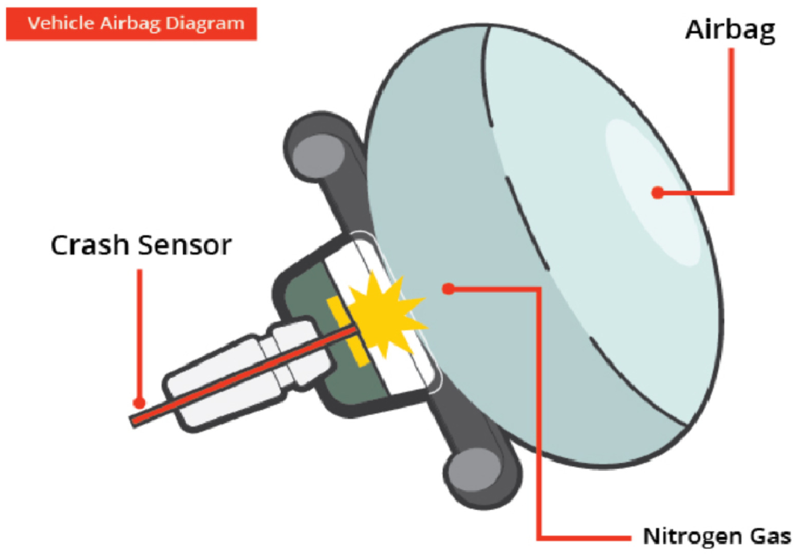
When used in a car, as shown below in Figure 1, an airbag inflates when a sensor detects an impact from the front or the side. The sensor sends an electric signal that starts a chemical reaction to inflate the airbag with harmless nitrogen gas and reduce the impact taken by the people in the car [10]. The electrical signal is sent to a canister that contains sodium azide, which detonates a small amount of an igniter compound. The heat from this ignition causes nitrogen gas to generate, fully inflating the airbag in 0.03 s [11]. For the purpose of this research, the chemical used will be black powder, because it performs the same task, is less hazardous to handle than sodium azide, and the reaction does not leave behind raw sodium like in a car’s airbag, which could also be extremely reactive [12]. Black powder charges are also available and can be purchased from most hobby shops for around $0.33 per gram. The only health hazards stated in its safety data sheet (SDS) are eye irritation and possible damage from the charge detonating [13].

Related Work

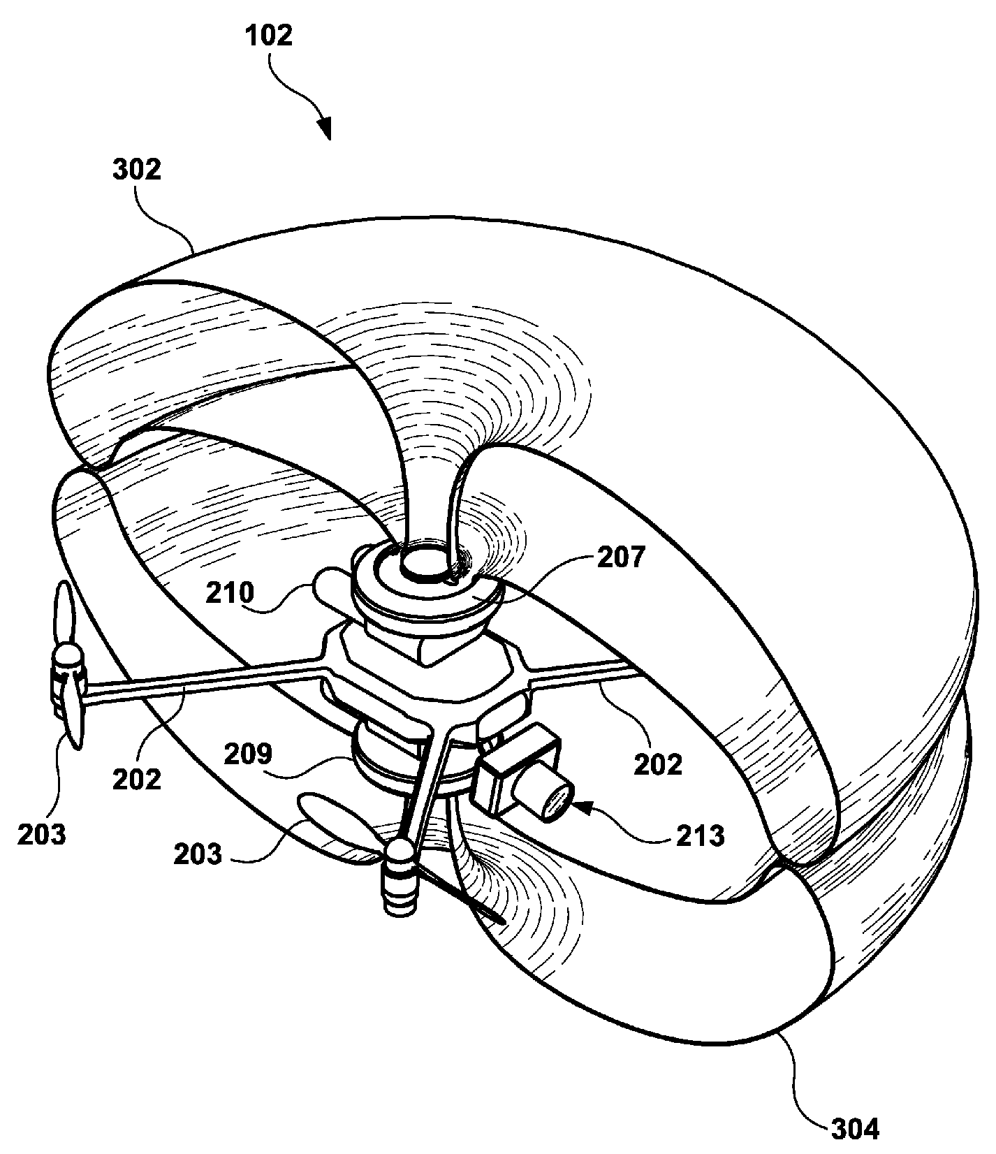
UAV airbags have been looked into before and even have a patent filed for specific use cases. Disney filed a now abandoned patent in 2015 for an airbag that they designed for the UAVs that would be used in their parks [14]. The main idea behind the use of the airbags was to protect park attendees if the UAV flies too low within specified areas. Shown in Figure A1 is how the airbag attaches to the UAV and the inflated state to encompass the UAV so that no part of it could collide with a park goer.
Using an airbag this way reduces the impact force in the event of a UAV failure, as shown below. The current Amazon delivery drone is the MK27, which weighs 36.25 kg [15] and flies between 60 to 122 m in altitude [16]. While in flight, if the MK27 suffered a failure and fell from an average height of 80 m, then it would reach a speed of 39.5 m/s just before impact. This would also mean its kinetic energy just before impact would be 2892.96 Joules. The human skull can withstand between 1779.29 to 4893.04 Newtons before fracturing [17]. Assuming that the collision distance of a skull is around 0.025 m, this would mean that the impact force on the skull would be 115.72 kN, which is much more than the human skull can bear. Although there are variety of factors that determine permanent damage to the head, this range provides us a goal of how much the impact force needs to be reduced by to make the safety system safer for those underneath it. If the collision distance was increased with an airbag, then the impact force experienced would be drastically reduced. Equations (1)–(4) show exactly how the airbag could reduce the impact force.
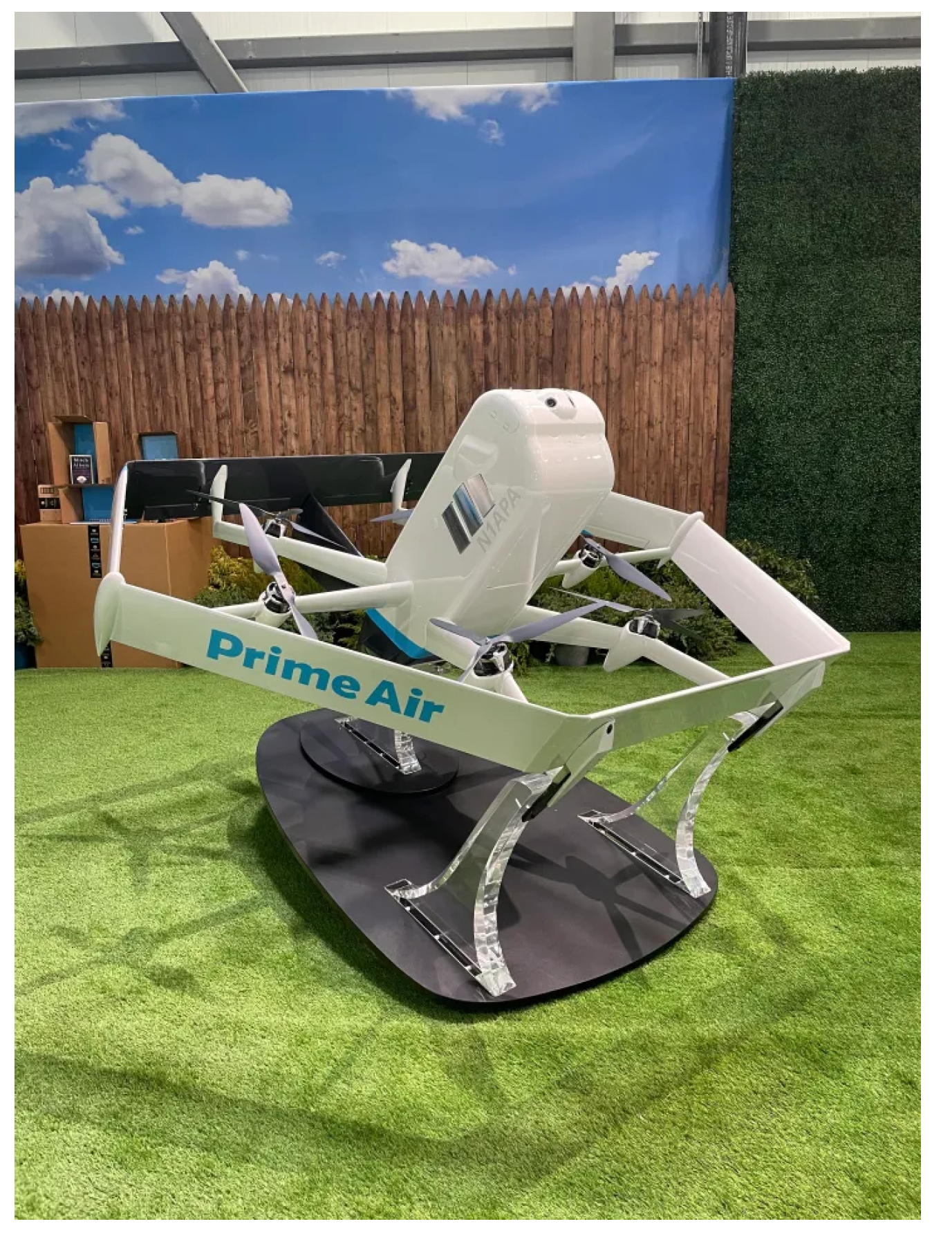
The current Amazon MK27 shown in Figure 2 weighs about 36.25 Newtons, which means its mass is 3.69 kg. In Equations (1)–(4), W is the weight of the UAV, g stands for the gravitational acceleration, h is the height of the drop, and s is the impact distance. Equations (3) and (4) come from [18]. For the non-airbag calculations, an impact distance of 0.025 m was used, as any more deformation than that upon a human head would be more than catastrophic. For the airbag based calculation, an impact distance of 0.35 m was used as the height of the appropriate airbag would increase the overall collision distance.
Mass of UAV = W / g UAV Mass = 36.25 / 9.8 UAV Mass = 3.69 kg
Potential Energy = m g h PE = 3.69 9.8 80 PE = 2892.96 J
Impact Force = K E / s Impact Force without Airbag = 2892.96 / 0.025 Impact Force without Airbag = 115178.4 N
Impact Force = K E / s Impact Force with Airbag = 2892.96 / 0.35 Impact Force with Airbag = 8265.6 N
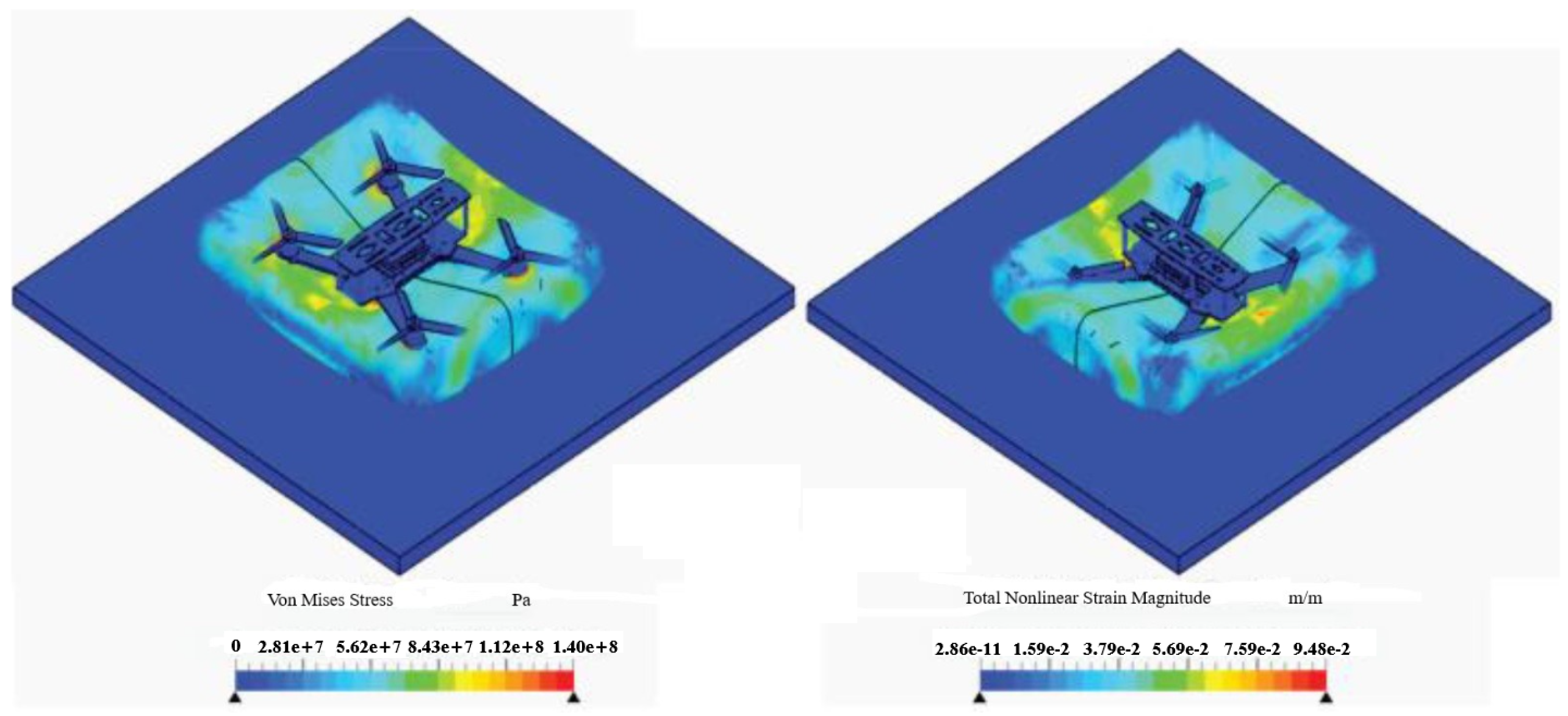
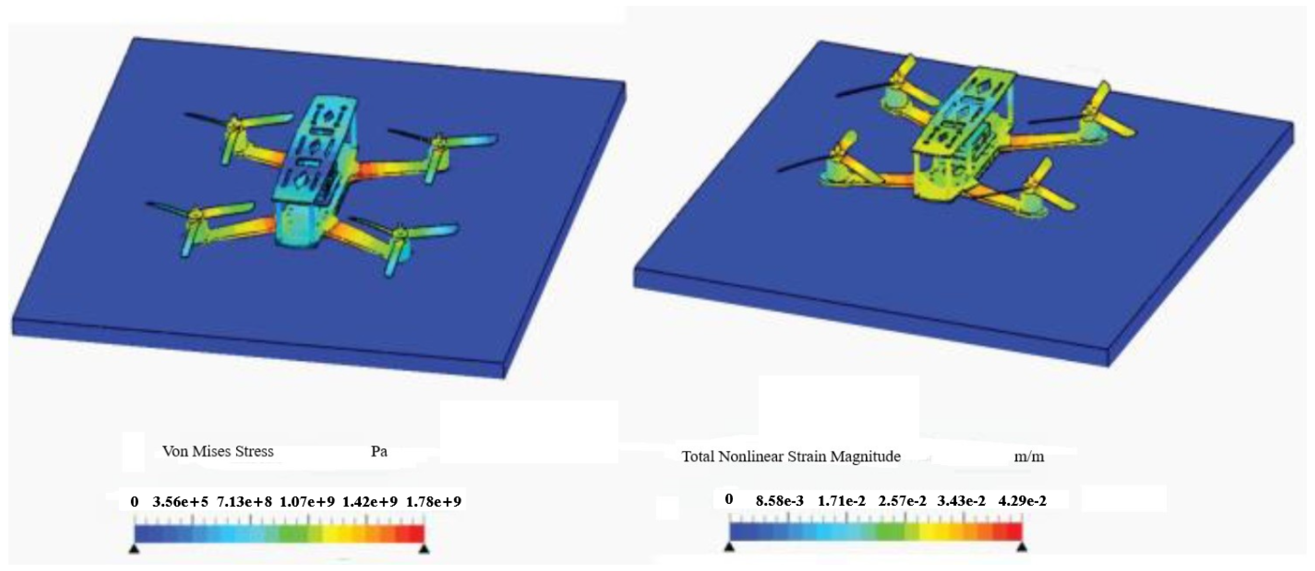
In "Design and Development of an Auto-Inflatable Airbag as the Failsafe System of an Unmanned Aerial Vehicle" [5] that covers the effectiveness of an airbag system, Ansari argues that the stress incurred by a falling UAV from 10 m with a collision speed of 14 m/s was 1.785 × 10⁹ Pascals, and the strain was localized on the arms of the UAV, which was 0.049. With the airbag deployed under the same conditions, the stress the airbag received was 1.405 × 10⁸ Pascals, and the strain of 0.09488 was entirely absorbed by the airbag, which had minimal effects on the drone structure. This means that the airbag reduced the overall stress by 1.64 × 10⁹ Pascals and absorbed all the strain so that the UAV experienced none. In another experiment on the development of a multirotor drone airbag, Cawthorne [6] also proves a distinctive style of airbag on a UAV. He then found that the impact from a 33.5 m drop was reduced from 130 Joules to 20 Joules, transferred to the frame of the UAV and lessened the impact velocity from 25 m/s to 10 m/s [6]. Figure 3 and Figure 4 detail Ansari’s experiment of the stress and strain reduction of a UAV dropped from 10 m with and without an airbag. Figure 5 depicts a fully rigged UAV airbag system pre and post deployment.
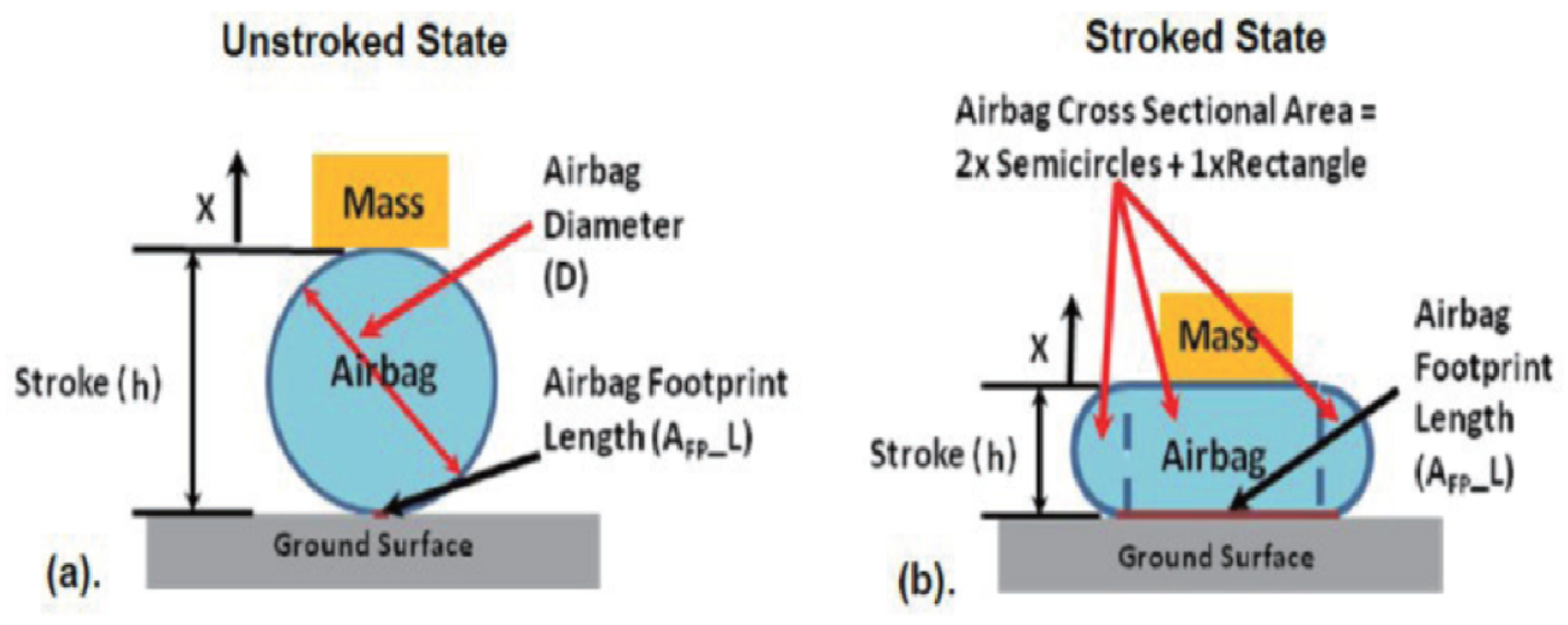
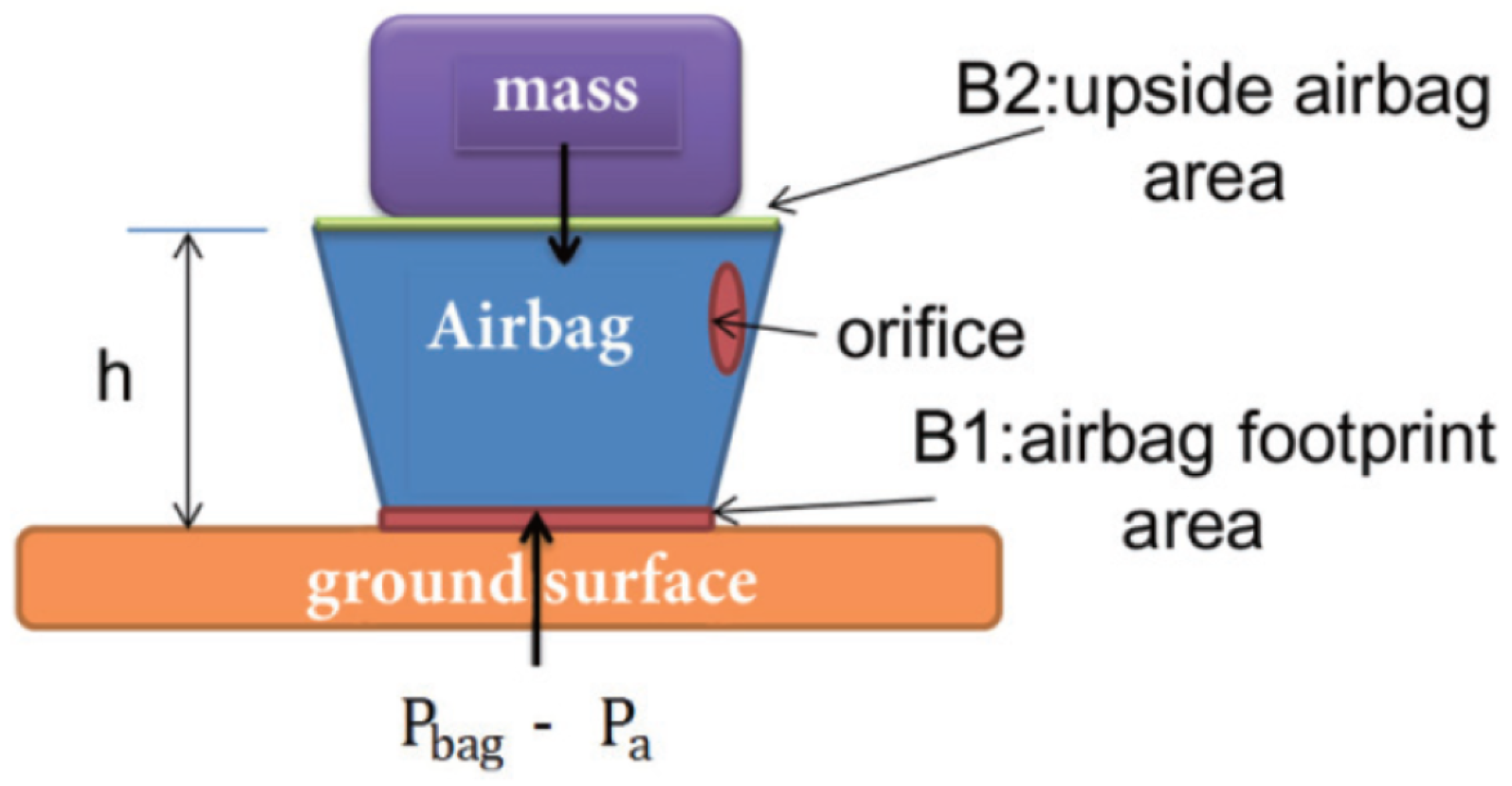
In [7], Masoud investigates the optimal airbag shape for a UAV. Since not all airbag shapes provide the same amount of impact absorption, Masoud found out that when the airbag pressure is critical, a cylindrical shape is the most optimal shape for an airbag [7]. However, for a falling UAV, the acceleration is the most critical aspect, which means that a truncated pyramid is the optimal shape instead [7]. Figure A2 and Figure A3 contain two images that show Masouds’ argument on (1) a cylindrical shaped airbag, how it deforms under impact, and (2) a truncated pyramid shaped airbag.
Another consideration is the rebound after the airbag collides with the ground or an object. Ansari and Cawthorne’s [5,6] solution was to not fully inflate the airbag. This means that the air in the airbag was compressed by the force of impact, but the pressure would not increase. This allows the airbag to not require a vent but instead adds more weight to the system as the airbag must be designed larger than necessary for gas used to inflate it. Masoud and Zhou [7,8] designed an airbag with a vent, which allowed pressure to be relieved upon collision so the air could not be compressed at all during impact. The conclusion of both papers was that the design and size of the vent port is critical, to relieve the necessary amount of air from the airbag upon impact as to slowly deflate but still retain the impact absorption. Both papers conclude that the optimal port size is dependent on the airbag shape and size: for a truncated pyramid, the optimal area is 0.025 m2, and for a cylinder, the optimal area is 0.05 m2 [7,8].
There have been a number of papers and projects [5,6,14] that focus on UAV airbag safety systems; however, none have approached this topic using a chemical inflation method before. All of the other papers cited use a separate air canister to inflate the airbag for smaller or similar UAVs. This research approaches the safety system with a newer inflation method and at the scale of larger UAVs being used for commercial functions. The contribution of this article is the designing, building, and testing of a chemically-inflated airbag that reduces the deployment time and footprint of the safety system to decrease drag, compared to existing drone airbags, while having a weight that can still be carried by the UAV, similar to Cawthorne’s work, where they proposed a 208 g airbag system on a 200 g UAV and fully inflated the airbag within 2 s.
Parachutes are currently one of the most common UAV safety systems, as they can be used at high altitudes and with most UAV designs. There are also a number of companies that specialize in manufacturing UAV parachutes like FRUITY CHUTES [20], as they even make a parachute system for the DJI Mavic Air 2 that is used in this research. The main downside to parachute-based safety systems is the time to fully deploy, as it requires the UAV to fall far enough for the system to work. Even with considerable work into improving the parachute safety system to withstand stronger winds, the UAV cannot be controlled during descent [21]. This means that while the UAV is descending and still has some amount of downward velocity, it can still make uncontrolled contact with a person or object underneath. Other safety systems, like a passivity-based control (PBC) also have issues with stronger winds and turbulence, making it less reliable in certain situations [22]. Another safety strategy that can be used during failures is gliding, where the multirotor drone converts to a glider after suffering a failure, similar to [23]. However, this concept necessitates inherent modifications to the aircraft’s airframe and propulsion architecture, limiting its applicability to existing UAV platforms and requiring bespoke design integration for each platform. In contrast, our proposed airbag safety system is externally attachable and can be integrated with existing UAVs without requiring fundamental changes to their core design. As discussed in [24], the best possible safety approach for UAVs would be to utilize a hybrid method, using multiple safety systems. An airbag system like the one proposed here, could be used along side other safety systems to guarantee that no injury occurs after a UAV failure. Because this safety system focuses mainly on the protection of mid-flight failures, another safety system could be incorporated to provide protection in the instance of takeoff or landing accidents. As a future research direction, a hybrid safety system can ensure that, if there is an issue during takeoff or landing, the UAV is guided to a clear area with no people or objects in the way.
As shown in Table 1, collectively, the existing body of work demonstrates that airbag-based safety systems can significantly reduce the impact forces and structural damage in UAV crashes. However, a critical limitation shared by most prior designs is their reliance on pressurized gas canisters that introduce trade-offs between deployment time and added volume. Studies by Ansari [5] and Cawthorne [6] show that while such systems are effective in energy absorption, inflation delays on the order of seconds can significantly reduce their utility in low-altitude failure events, where impact occurs almost immediately after loss of power. Similarly, optimization efforts focused on airbag geometry and venting strategies primarily address post-impact dynamics, such as rebound and pressure relief, rather than the equally critical pre-impact requirement of ultra-fast deployment. This gap highlights the need for an alternative inflation strategy that prioritizes the response time without substantially increasing the volume. In this context, the present work advances the state of the art by introducing a chemically actuated airbag system that directly targets this unresolved limitation, enabling sub-second deployment while maintaining the proven benefits of airbag-based impact attenuation.
The rest of the paper is organized as follows: Section 2 covers the methodology of research and each section of the safety system. Material, Circuit Design, Gas Generation, Detonator System, and System Design are all addressed in this section. Section 3 presents the results of the safety system and covers how it was tested. Section 4 concludes the research, details potential improvements, and provides Supplementary Material of the testing conducted, followed by Appendix A.

2. Methodology

The purpose of this research is to make a self-inflating airbag that can detect a free-fall situation and then inflate the airbag before impact. To do this, there are a number of systems that need to be researched and tested, such as the shape and material of the airbag, the inflation method, the attachment system, and the control circuit. After the airbag system works and is ready for testing, the drop test can commence and determine how effectively it lessens impact.

2.1. Material

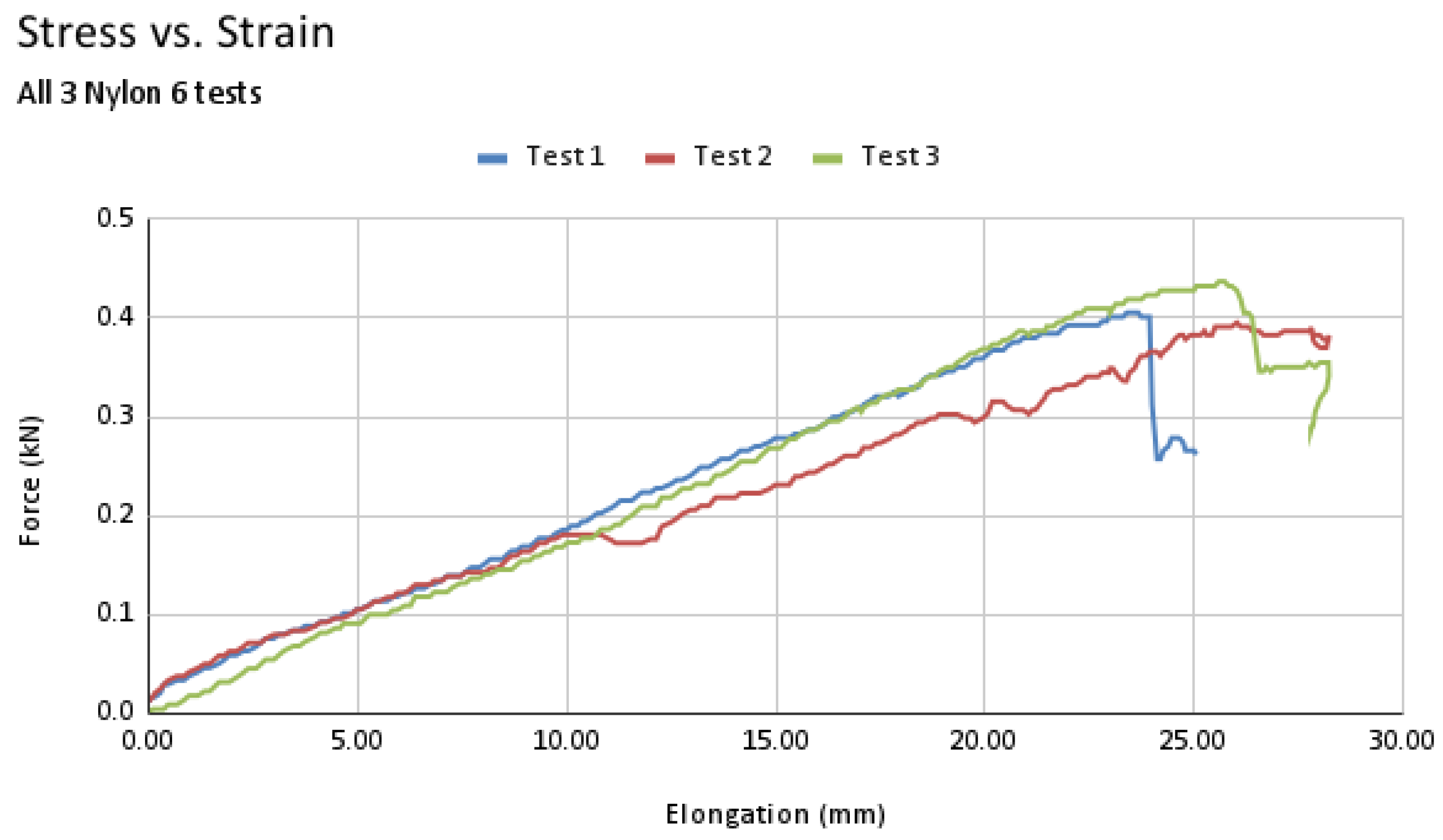
First and foremost, the shape and material of the airbag need to be determined. For this research, a Nylon 6 fabric was selected over Nylon 6.6 and polyester due to its high durability and malleability. Nylon is also one of the more utilized fabric types for airbags that need to be more durable [25]. The fabric used for this research includes a ballistic weave, making it stronger and less prone to puncturing or tearing. The tradeoff for this being that the fabric weighs more than most other fabrics; an 8 by 12.5 cm test strip of the fabric weighs around 2.6 g while Nylon 6.6 and polyester weighed 0.8 and 0.6 g, respectively. This is only exacerbated, as more material is required for each airbag shape and size. The test strip was also put through a tensile test on a TecQuipment Tensile Testing Machine (SM1002, TecQuipment, Nottingham, UK) under the ASTM D5035 [26] to determine its tensile strength and stress–strain curve, as shown in the graph in Figure 6. For this tensile test, the fabric was gripped on either end with clamps and pulled apart within the tensile testing machine. No special preparation was necessary for this test, and each test strip was pulled apart at a rate of 1.1 mm/s.
As seen in Figure 6, the average tensile strength of the Nylon 6 used is around 0.4 kN/mm (400,000 N/m) making it an ideal fabric for airbag construction and impact reduction. Because the airbag needs to retain air during collision and not break on impact, the higher tensile strength ensures that the airbag will not rip or tear. Various airbag designs and sizes were then compared to determine the best one for this project. Detailed in Table 2 is a comparison of each design by size, weight, and volume.
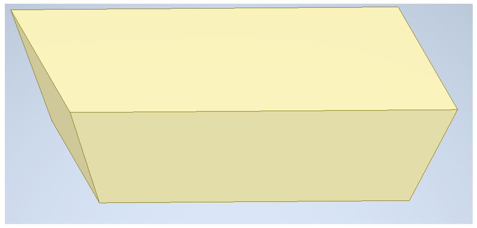
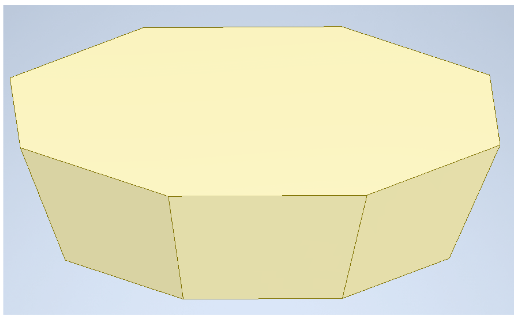
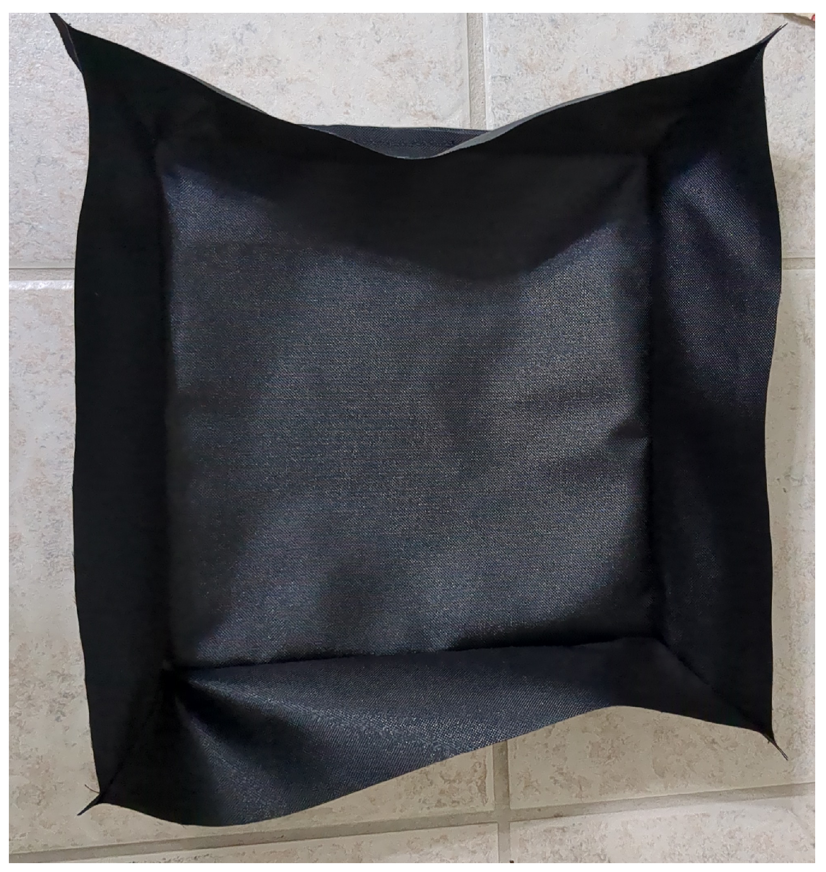
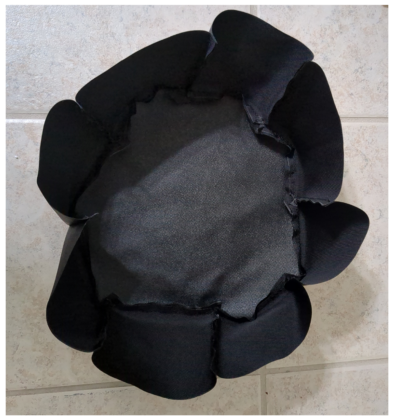
As Table 2 shows, the truncated shapes are much heavier than the disc-shaped airbag and hold more air when inflated. Each of the truncated shapes weighing more and requiring more gas to completely fill them ended up being a large detriment to their design. As the design iteration continued, the size of the airbag shrank to reduce the amount of gas necessary to fill the airbag, and the shape became simpler to make production easier and minimize the overall weight of the system. The final design of the airbag was a 12 inch disc shape that still covered the body of the UAV system but required less gas to inflate and was much lighter than its counterparts. The 12 inch disc was chosen because its size allowed it to function properly and cover the bottom of the UAV, but reduce the weight of the system as much as possible and reduce the amount of gas generation necessary to fill the airbag.
Table 2. Airbag design comparison.
Airbag MaterialShapeDiameter (in)Weight (g)Volume (L)
Nylon 6Truncated Square (Figure 7)1599.77
Nylon 6Truncated Octagon (Figure 8)1595.66.5
Nylon 6Disc1574.36
Nylon 6Disc1355.84.5
Nylon 6Disc1247.53

2.2. Circuit Design

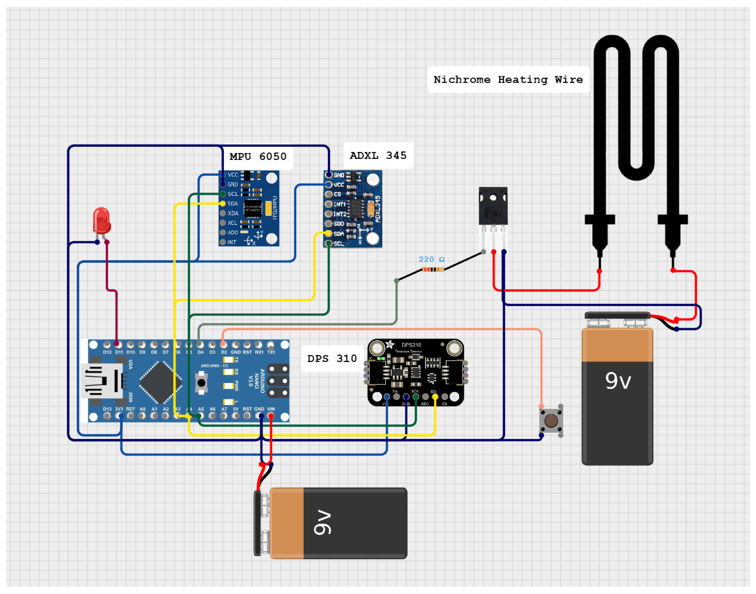
The inflation of the airbag is controlled by an Arduino nano (Arduino, Monza, Italy) and a system that was made specific for this UAV application. It uses an accelerometer (MPU 6050) and a barometer (DPS310) to detect whether the UAV is in free-fall and whether it is close to the ground. Once both conditions have been met, a Nichrome wire is heated to trigger the inflation of the airbag system. To ensure that this process happens rapidly, a separate lithium-ion battery is used to heat the wire in a fraction of a second. Because the time it takes for a falling object to reach the ground is quite rapid, a minimum effective height needed to be set. Here, 12 m was used as a standard measurement; included in Equation (5) is the time it takes for an object to reach the ground when falling from said height. This emphasizes the need for the circuit to sense the fall and trigger the detonator all within a fraction of a second. Equation (5) comes from [27]. This height threshold was selected to give the system plenty of time to detect the falling condition and react within time to deploy the safety system before making contact with anything below the UAV.
Time to reach ground from free - fall = ( 2 h / g ) t = ( 2 12 / 9.8 ) t = 1.56 s
The purpose of this system is to detect whether the UAV is in free-fall, defined as −9.8 m/s2, and within 12 m of its starting height. Once the circuit receives power, the accelerometer and barometer are initialized but not calibrated yet. During this, it has a check to see whether the ground level button has been set before running. This ensures that the system is not running immediately upon power on and potentially causing a false deployment. Once the ground level button is pressed, the accelerometer and barometer are both calibrated and set to 0, and the system is now active. The accelerometer is calibrated to read 0 m/s2 while at rest, and the barometer also reads the current pressure as 0 at the starting location after the ground level has been set. During testing, the accelerometer remained consistent with its reading and within 0.1 m/s2 of the experienced acceleration. This drift was never large enough to necessitate correction; so, the accelerometer drift was left as is. The barometer, however, was not as consistent, although able to remain within 0.25 m of the current height at any given time. An LED is also included to provide visual feedback when the sensors are calibrated. Setting up the system this way also ensures that the safety system can be used from any height, because the starting height is always considered 0 m. Once both the downward acceleration and lowered height conditions have been met, the MOSFET is then used to quickly close the loop to the other battery and heat the Nichrome wire. When the MOSFET is triggered to heat the wire, the LED also illuminates to confirm that the system is working as intended. Once heated, the temperature of the wire causes a reaction with the chemical used to inflate the airbag. This system also includes a buffer to the height that the system checks to increase the accuracy and decrease the chance of accidental discharges due to minor height fluctuations. The height buffer adds a small delay to the system to guarantee that the UAV crosses the height threshold before deploying. Table 3 shows the correct conditions in which the system would deploy the airbag. If the UAV were to fall from any of the listed heights, the trigger condition details how the system would react.
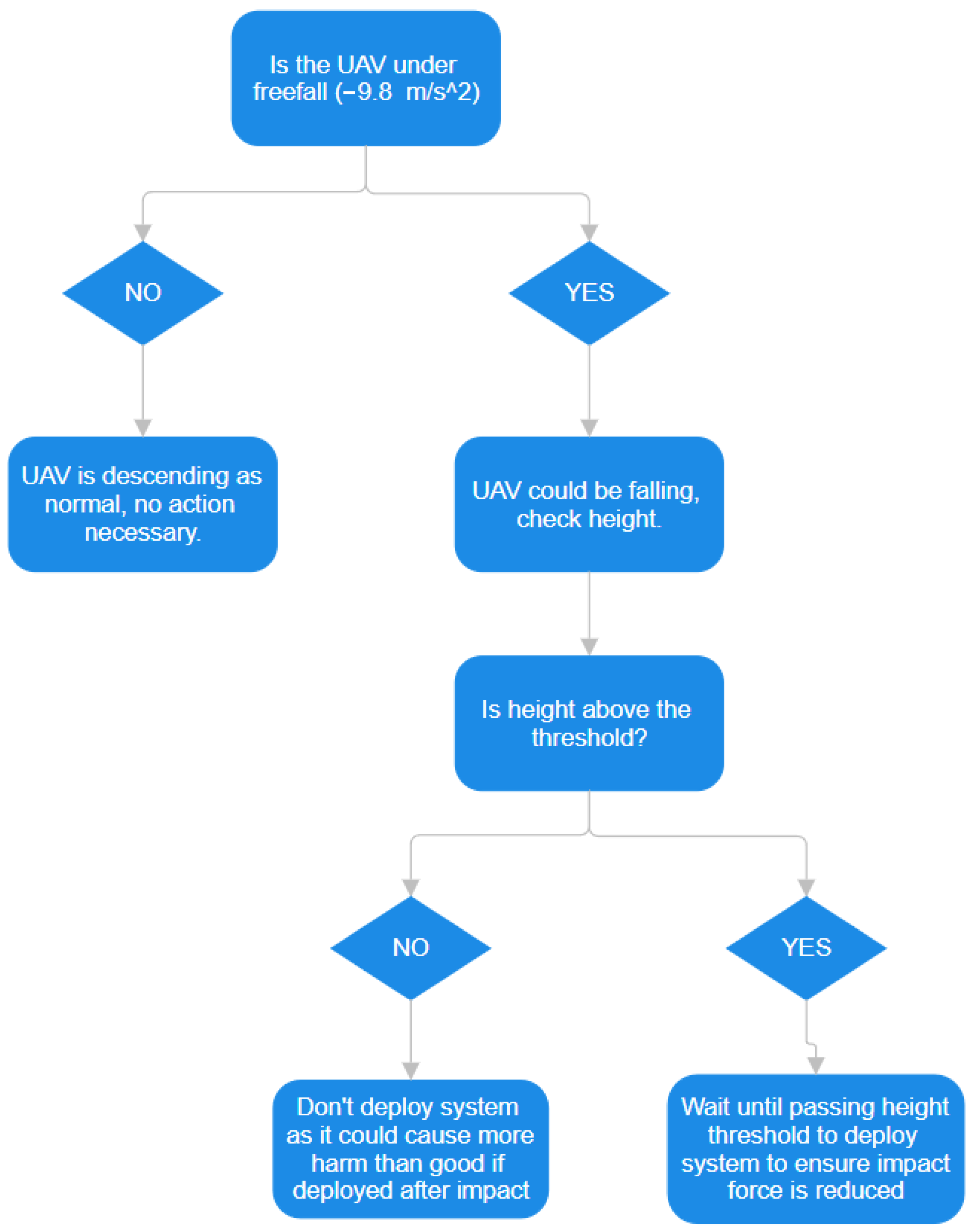
This is set up so that when falling from a greater height the airbag will deploy after passing the 12 m height mark. Since the height threshold is 12 m, this safety system can be used from any height above such, meaning that any UAV flying between the range of 12–122 m could use a system like this. The 12 m height threshold was chosen because that gives the system plenty of time to react and inflate the airbag before impact (1.5 s). Any lower would cause issues if the system triggered too late or caused the airbag deployment to be delayed. If there is an issue with the timing of the system from the 12 m height, the threshold can be increased as well to provide the autonomous system more reaction time. If the airbag attempted to deploy while under the minimum height necessary, it could cause more harm to anything underneath it as the inflation would be delayed. This could mean that the UAV would still hit any object underneath without the airbag and then fill the airbag, causing even more damage afterwards. The acceleration is also just as important, as a false detonation could cause the UAV to fail as well. If the UAV was descending in a normal operation, but too fast for the accelerometer, it could cause a false detonation of the airbag. This is why the height and acceleration conditions must be met before the airbag deploys. If the airbag were to deploy above that threshold, the gas generated would still be contained within the airbag as it is manufactured to be airtight. Figure 9 and Figure 10 show the flowchart and wiring diagram of the autonomous deployment algorithm, respectively.

2.3. Gas Generation

The initial idea for this research was to use a combination of explosives to manufacture a detonator for the purposes of generating gas rapidly. However, this proved quite difficult, as the explosives used (Mercury (II) Fulminate and Nitroguanadine) did not produce enough gas to completely fill the airbag, and even a smaller controlled blast damaged the airbag structure each time. Thus, the switch from explosives to black powder was made. The black powder could be burned off rapidly to generate gas but not detonate and damage the airbag. This does provide a new challenge, however, as the burning of black powder is around 1400 °C [28], and the maximum temperature the Nylon 6 can tolerate is around 210 °C [29]. The heat generated by the black powder burning can be mitigated through the use of an isolated chamber to control the burning process, but another endothermic element needs to be added to reduce the temperature of the remaining gas. Sodium bicarbonate is then added to the detonator shell to reduce the overall temperature experienced by the airbag. As sodium bicarbonate is heated, it begins to decompose and absorb heat from the surroundings [30]. Since the sodium bicarbonate is added to the detonation chamber, the heat of the gas that inflates the airbag is drastically reduced to safer levels. After each test, the gas within the airbag was cool enough to handle without any protection. The airbag is also coated with a thin layer of silicone to retain as much gas as possible and increase the amount of heat the airbag can tolerate. The silicone coating is rated up to 300 °C [31] and much more resistant to burning, meaning that any of the fire from the black powder that escapes the detonator shell will not damage the airbag. To ensure that the charge burns properly, an oxidizer (Guanidine Nitrate in powder form) is added as well to facilitate the burning of the black powder. Because the airbag is sealed to ensure no gas can escape, the oxidizer allows the charge to burn completely and inflate the airbag. The gas generated from the explosive method was nowhere near the required amount, around 0.6 L with a 5 g detonator, while the black powder method generated the required volume, around 3 L, each time with a 5 g charge.
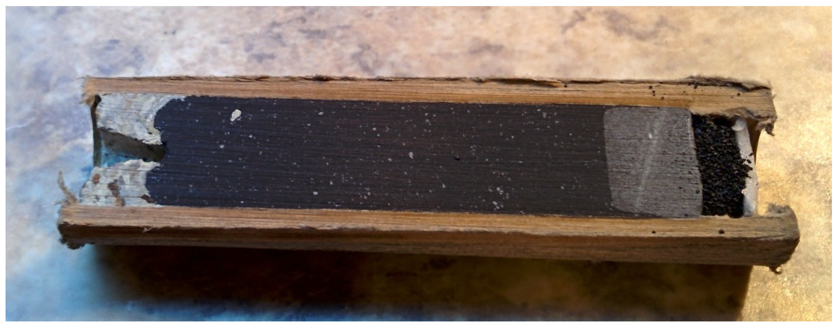
The black powder charges are sourced from the Estes C6-5 rocket (Estes, Penrose, CO, USA) charges shown in Figure 11 because they are already compressed into cylinders and easy to fit into the detonator shell. After multiple tests, the maximum amount of weight of black powder the system can use to generate gas without producing too much was found to be around 4.7 g. This allows the Nichrome wire to heat the black powder charge rapidly enough to inflate the airbag in a matter of seconds and produce enough gas as to not overfill the airbag. The C6-5 charges were used specifically because the weight of the black powder in the charge is more than double the necessary amount for the airbag inflation, meaning that each C6-5 charge can be used twice for the airbag.

2.4. Detonator Design

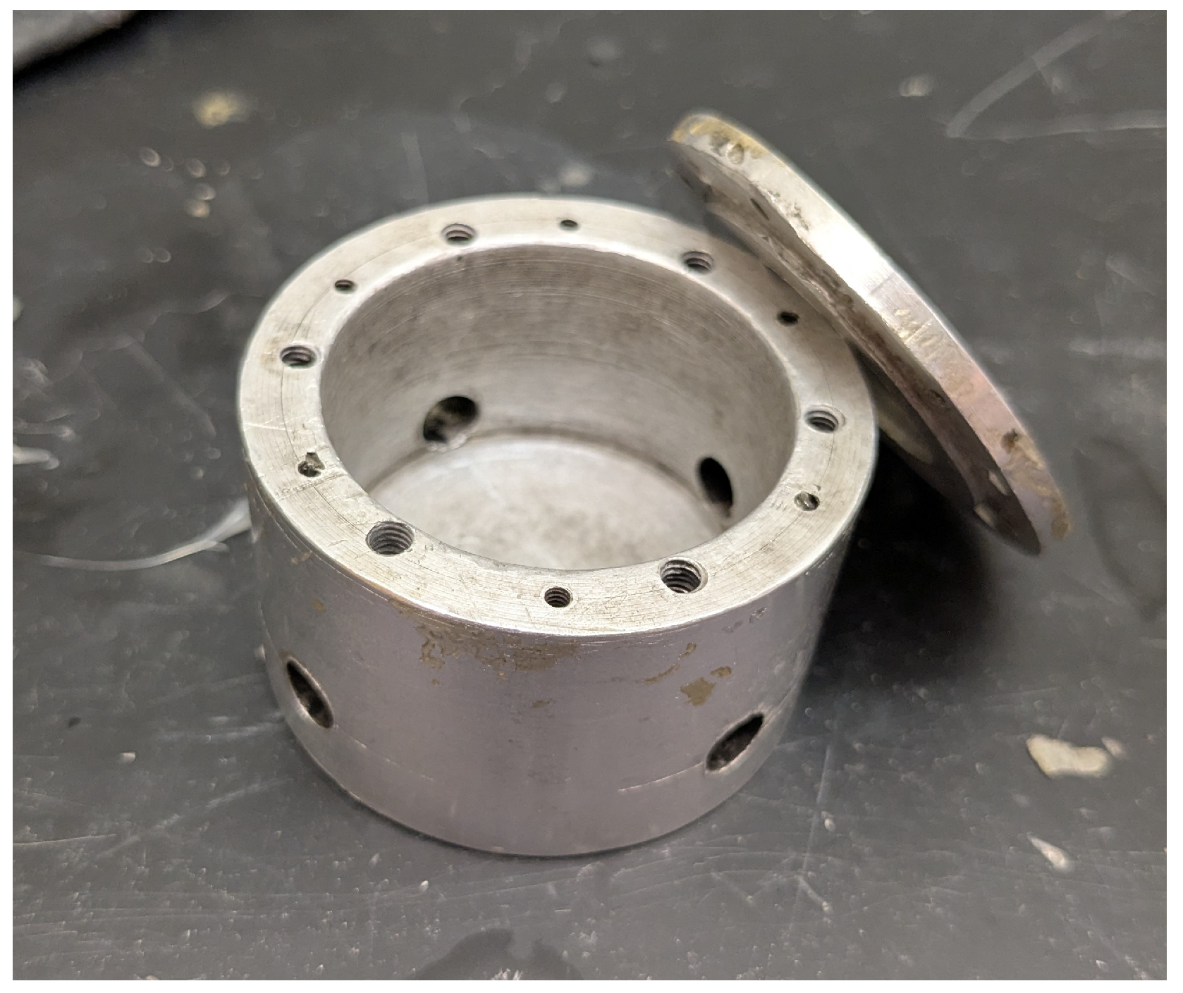
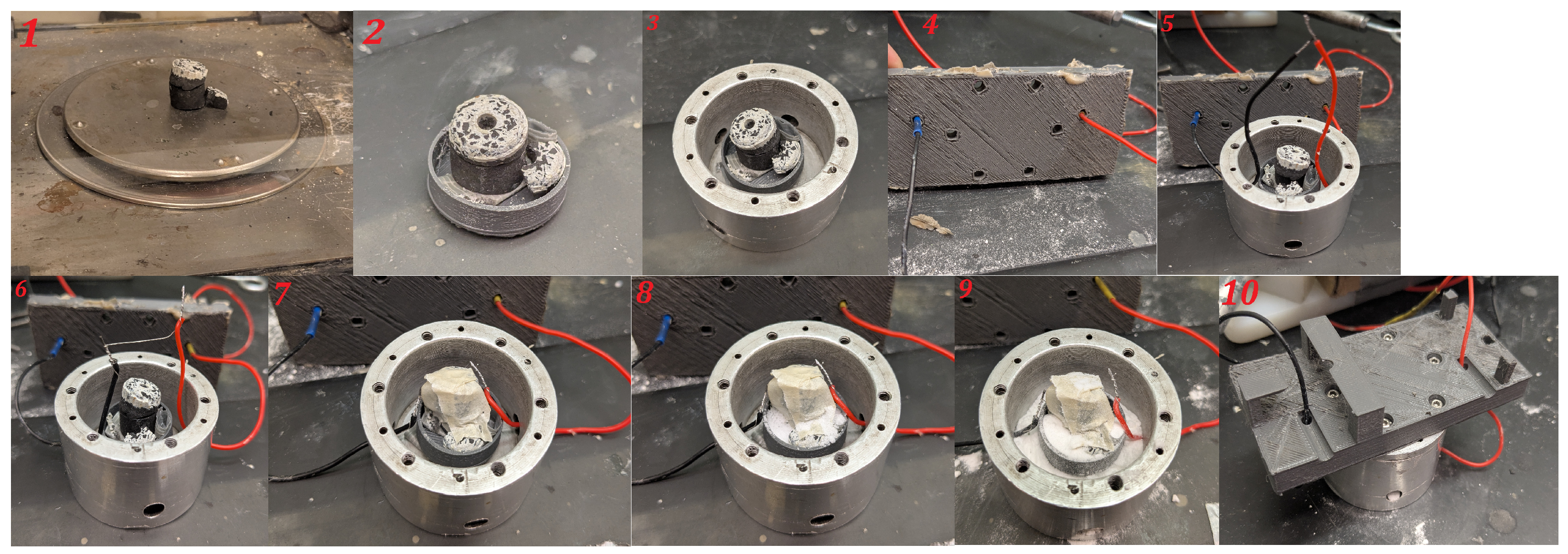
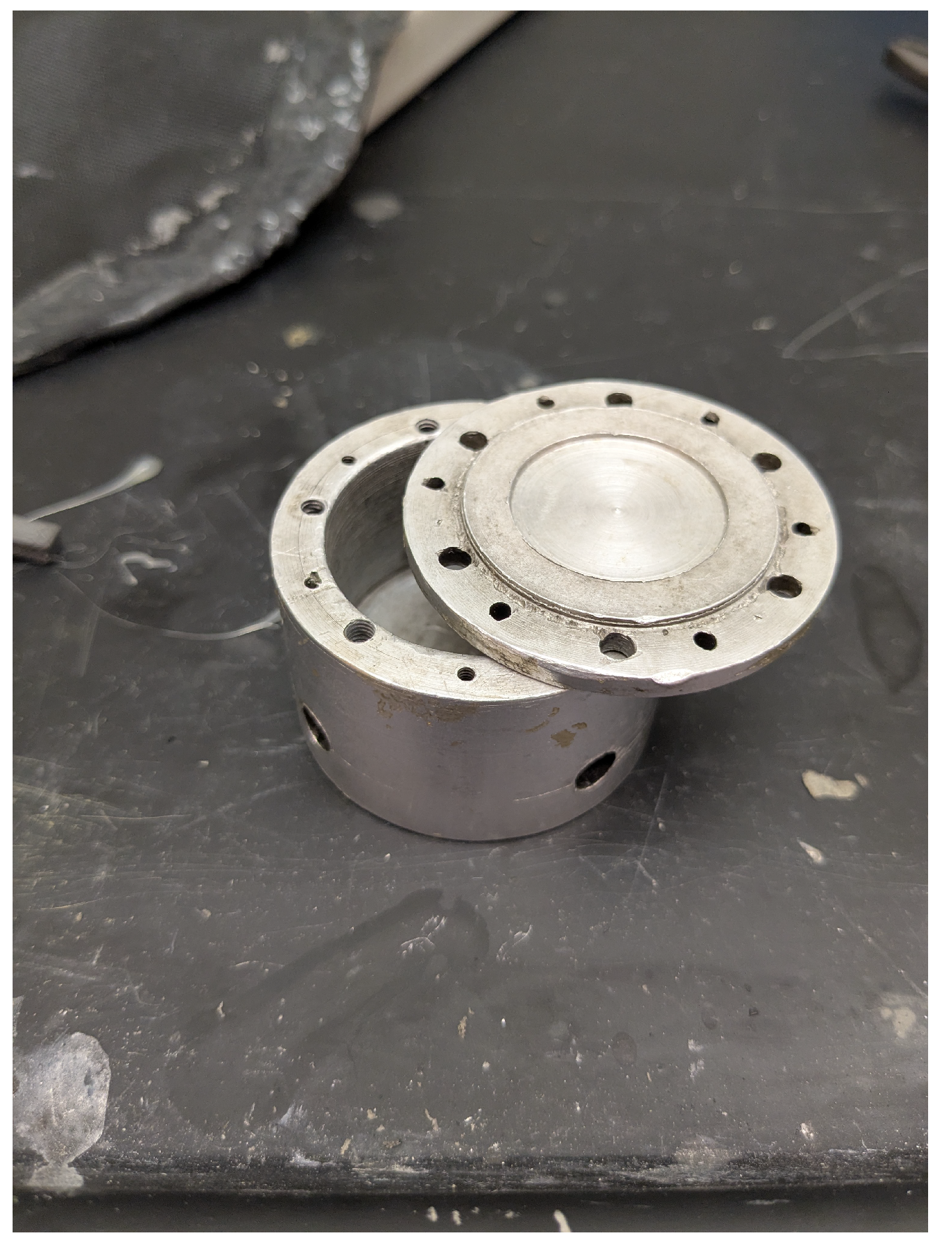
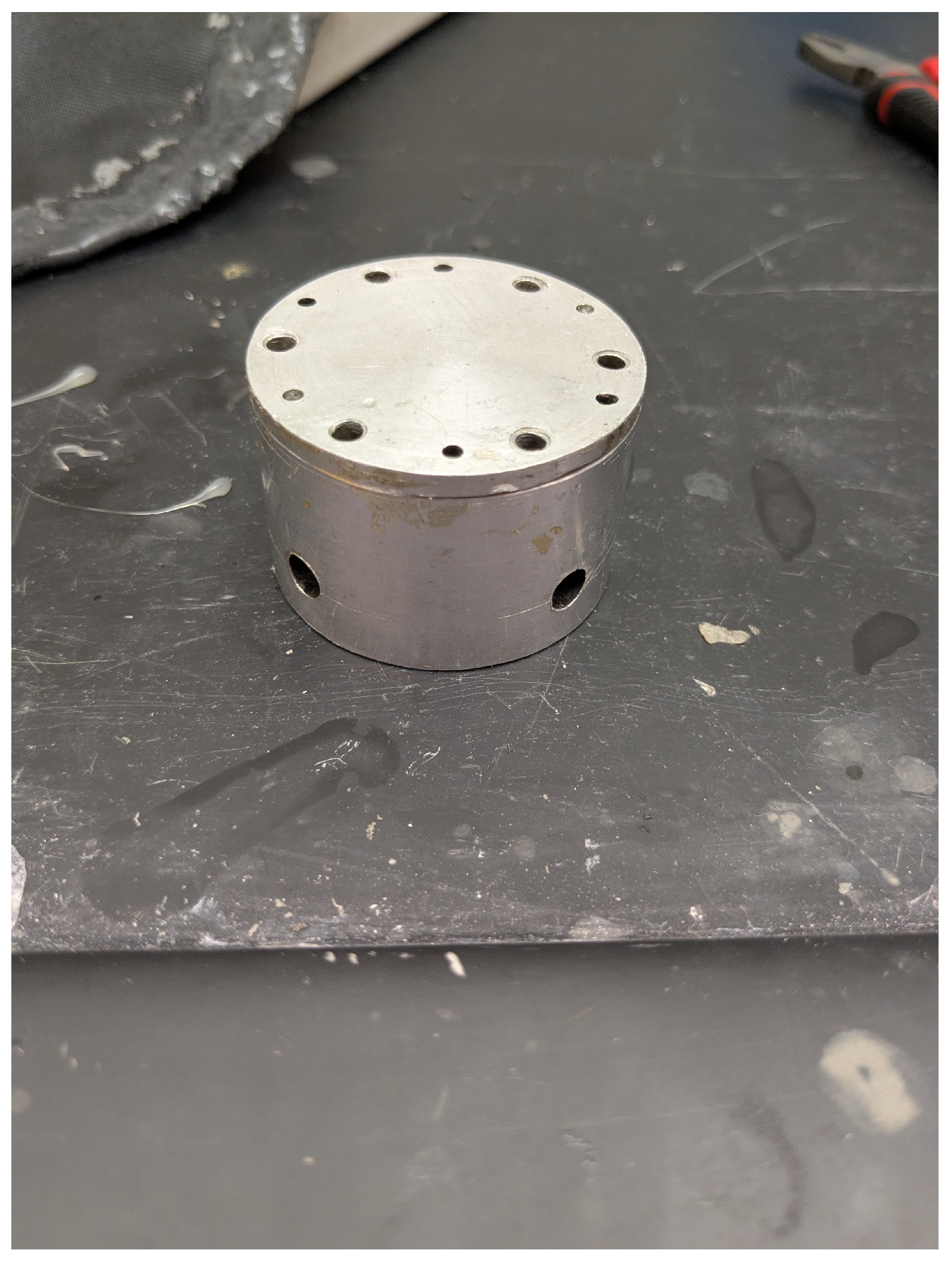
After the black powder is weighed, it is then placed in a shallow 3D-printed half-cylinder to keep the charge in place and to create an area in which the sodium bicarbonate powder can rest around the black powder without escaping. The nichrome wire is then added to the chamber and attached to the black powder via tape. The whole thing is then placed into the detonator shell and ready to use. The detonator shell was manufactured with durability and ventilation in mind; so, it can withstand the blast that was initially planned and vent out as much gas as possible. The detonator shell, as depicted in Figure 12, Figure A6, and Figure A7, contains four venting holes for gas to inflate the airbag on the sides of the cylinder. The lid is manufactured to create a seal on the inside of the chamber so that all the gas is vented down into the airbag and none of the hot gas escapes toward the UAV. The lid is then sealed with six screws to ensure a tight seal and is then ready to be used.
The design of the detonator shell is necessary to keep the burning of the black powder separate from the UAV and the airbag. As the black powder burns, the sodium bicarbonate melts and absorbs part of the heat from the reaction and the chamber itself also absorbs the heat itself before the gas escapes into the airbag. Detailed below is how the detonator chamber is prepared before use. Detailed below is how the detonator chamber is prepared before use and a figure depicting said; Figure 13.
  • The black powder is weighed and cut to the proper amount (around 4.65 g).
  • The black powder charge is taped to the bottom of the 3D-printed half-cylinder.
  • The half-cylinder and black powder charge are then taped to the bottom of the detonator shell.
  • Heating wires are threaded through the snap plate.
  • The heat wires are added into the detonator shell.
  • Nichrome wire is attached to both ends of the heating wires.
  • Nichrome wire is then taped onto the black powder charge to ensure constant contact.
  • Oxidizer is added to the bottom of the half-cylinder around 0.5 g.
  • Sodium bicarbonate is then added around the black powder in the half-cylinder and around it for extra caution, enough to cover the bottom of the detonator shell (around 2.8 g).
  • The detonator shell is then sealed and ready to use.
  • The detonator shell is then loaded into the airbag and sealed in with glue so no gas can escape.
  • The airbag system is now ready for use.
Figure 13. Steps to prepare the airbag.
Drones 10 00199 g013

2.5. System Design

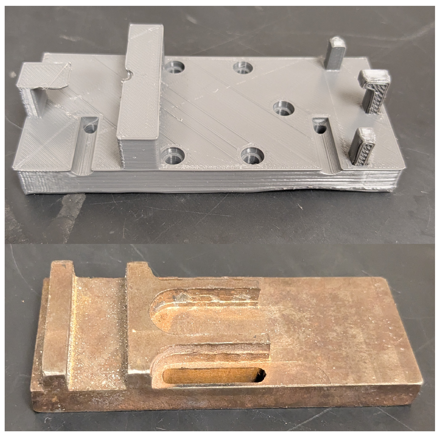
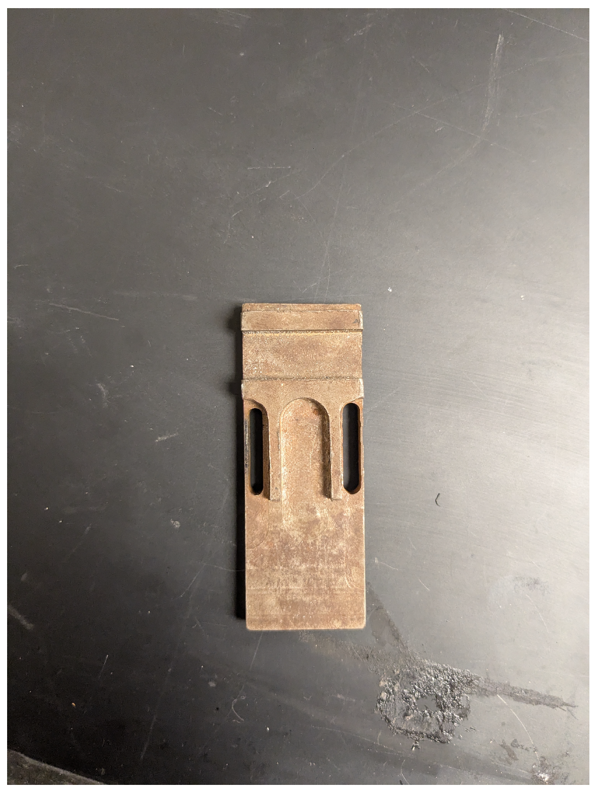
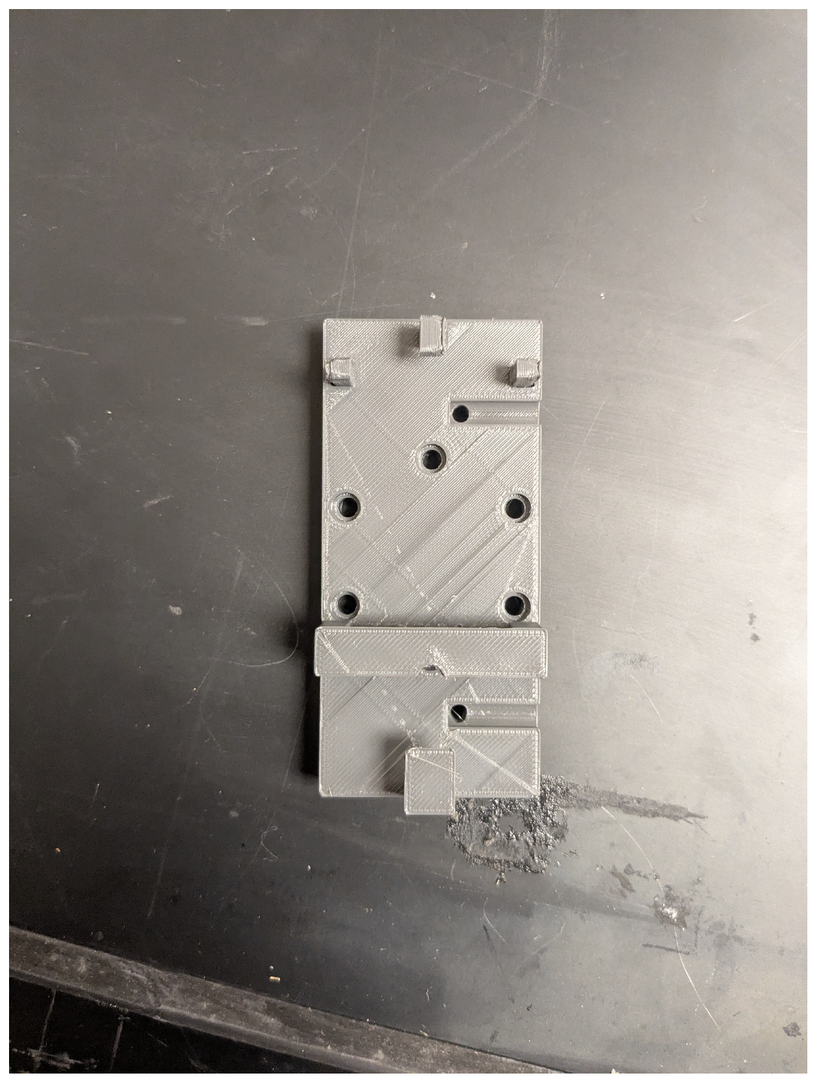
The airbag system attaches in a two-part fashion. The lower part, titled the “Snap Plate”, is fastened into the airbag and creates a seal after fastening the detonator shell charge onto it. The upper part, or the “Protection Plate”, is a solid plate that fits into the snapping plate and attaches to the UAV via a belt system that can be pulled tight and hold the airbag system in place. Each of the plates are made of different materials as is necessary for their purpose. The snap plate is made of 3D-printed nylon, because nylon is resistant to the high heat that the black powder puts out while burning and allows the snap plate to be manufactured rather easily for more airbags. The protection plate is made from a mild tool steel to absorb any residual heat and to be used multiple times without needing to be changed. This does increase the weight of the system but guarantees that the protection plate will do the job, and the chance of its failure is minimal. Since the snap plate is sealed into the airbag, it does not need to be reusable as each airbag is designed to be single use only. Shown below is the snap and protection plate in Figure 14.
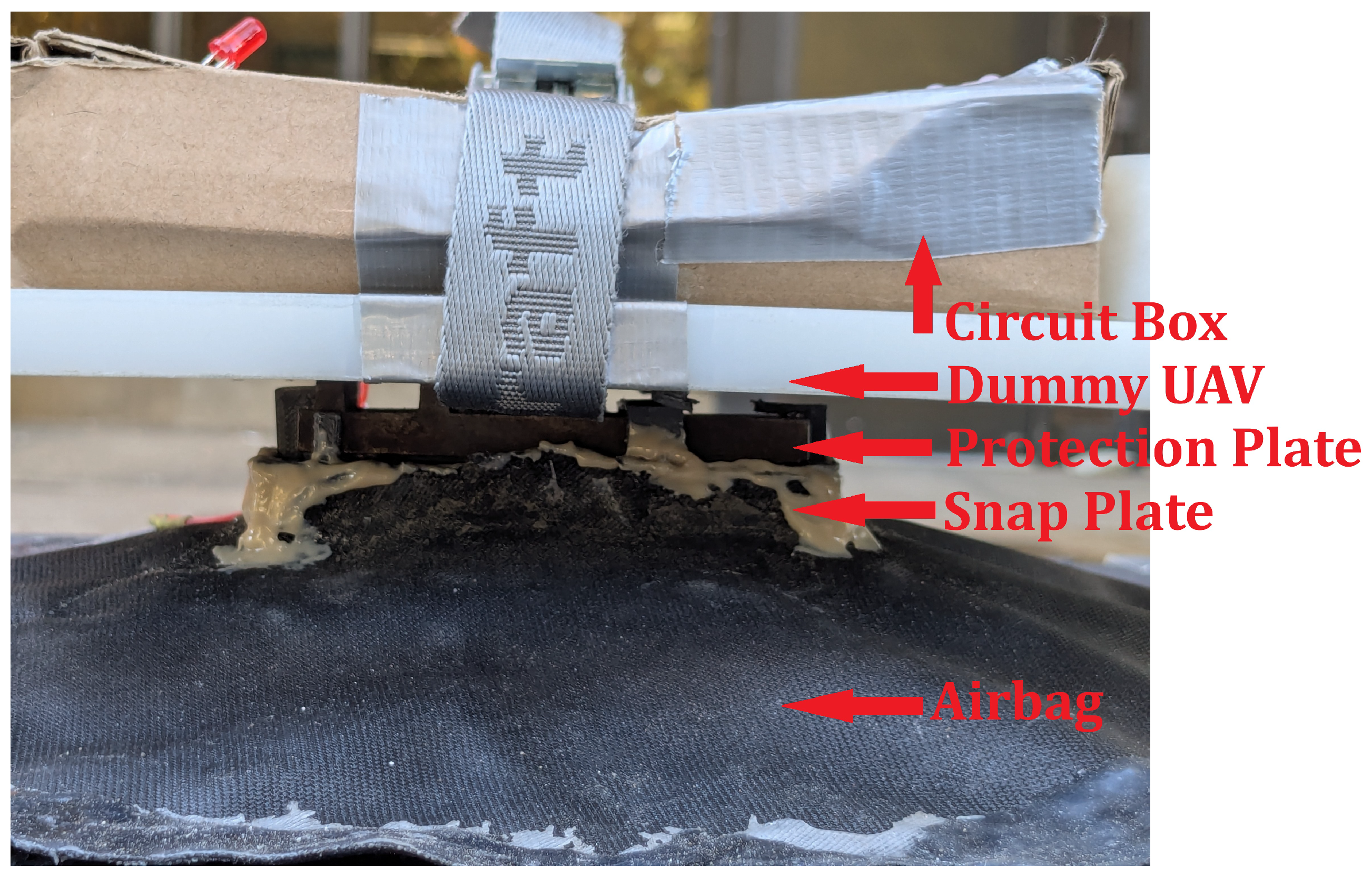
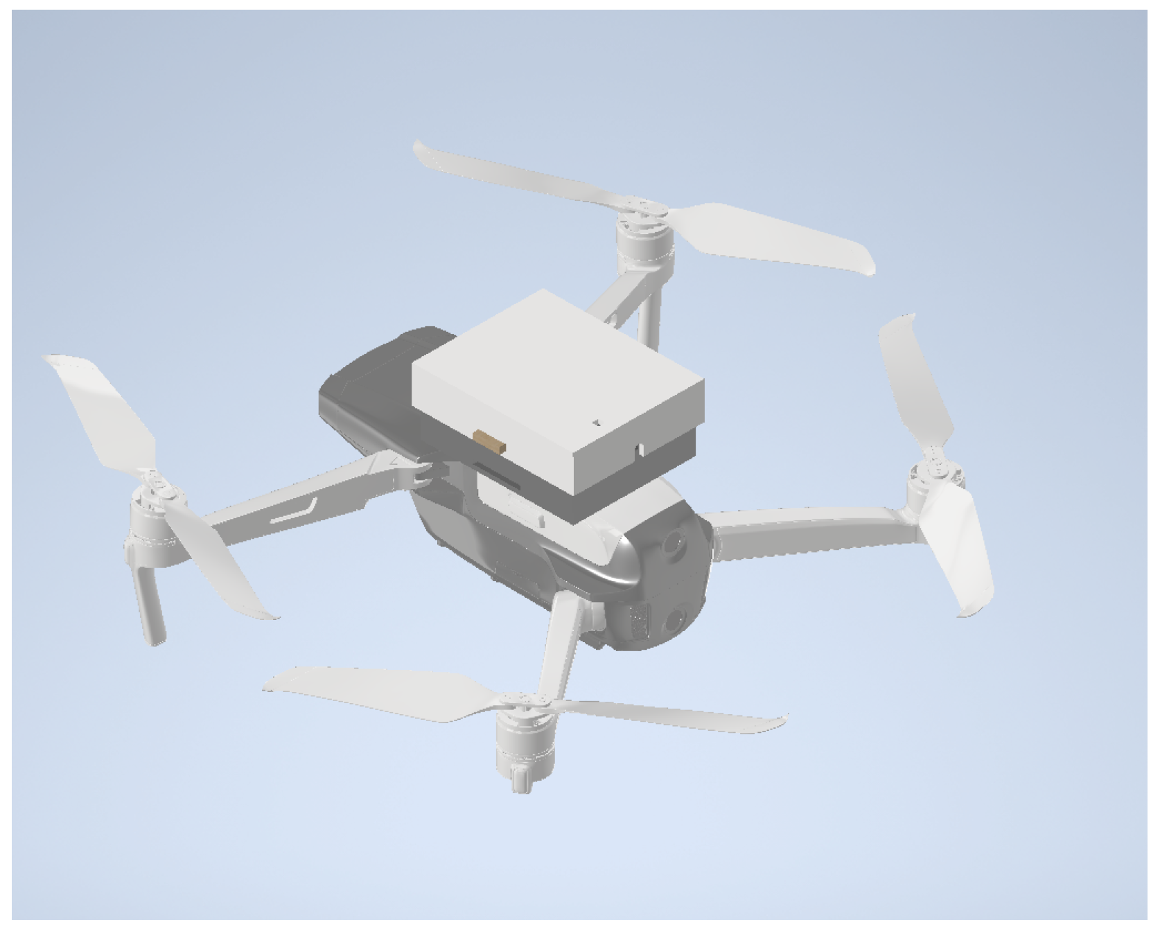
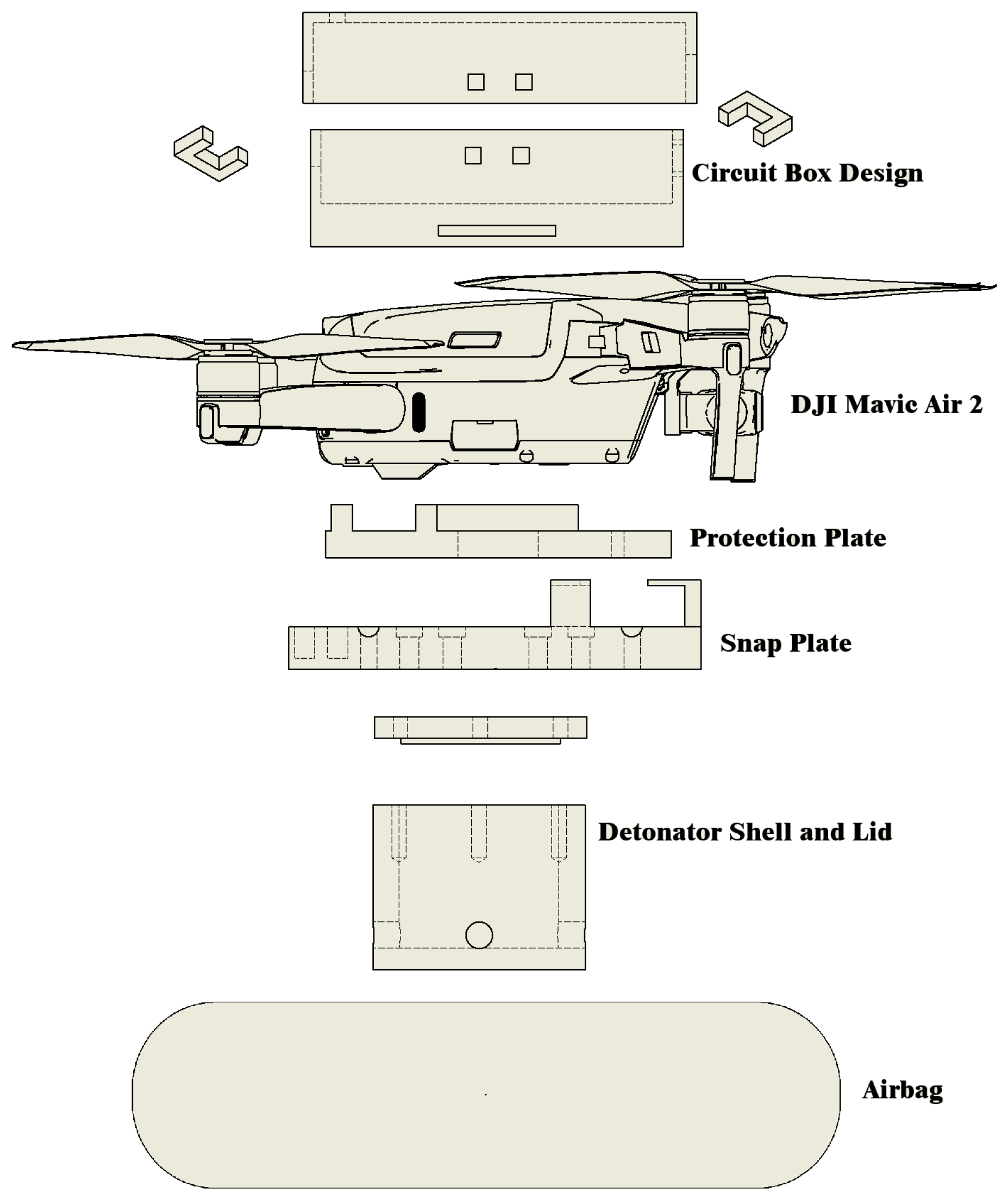
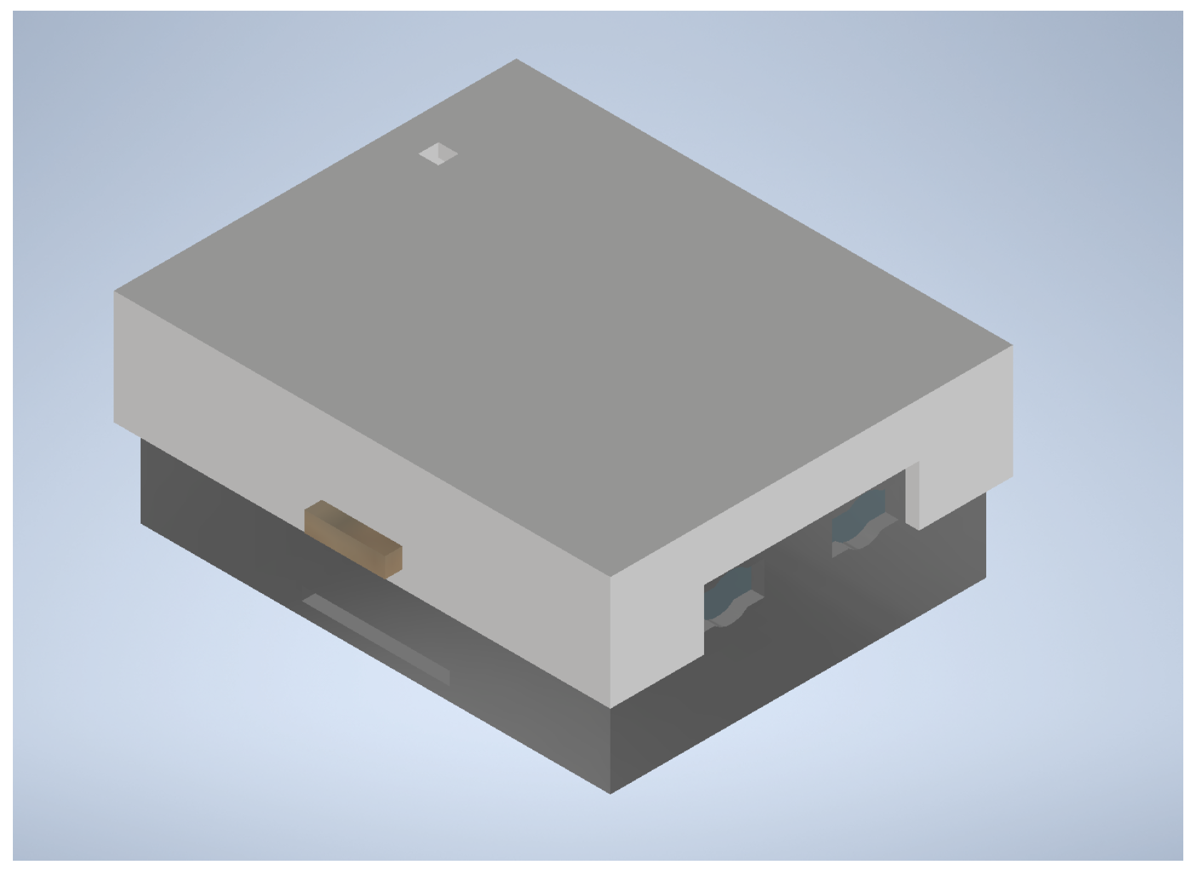
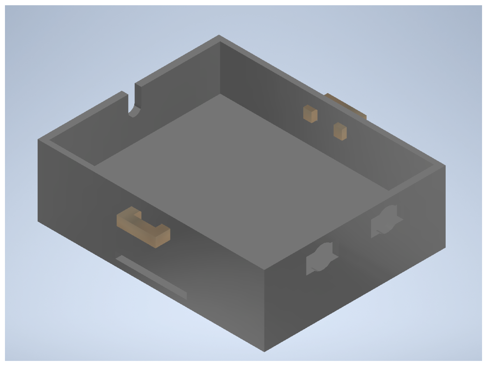
Using a belt system that feeds through the protection plate, the circuit for this is attached on top of the UAV. The circuit box is also 3D printed from nylon for ease of manufacturing and to reduce the weight of the system. The circuit box would normally rest between the UAV blades so that it is not in the way and uses a couple of insulated quick connect plugs so that the airbag can be swapped out easily. Table 4 provides a breakdown of the total weight of each section of the safety system. Figure 15, Figure 16 and Figure 17 all depict how the circuit attaches to the UAV and each component of the safety system.

3. Results

To determine a basis for the downward acceleration during an impact, two different accelerometers were used to record the acceleration experienced by the UAV. An MPU 6050 and an ADXL 345 are both used, because just one accelerometer can be inaccurate and give uncertain readings. By using both accelerometers, the readings of each can be averaged to obtain a more consistent acceleration during the test.
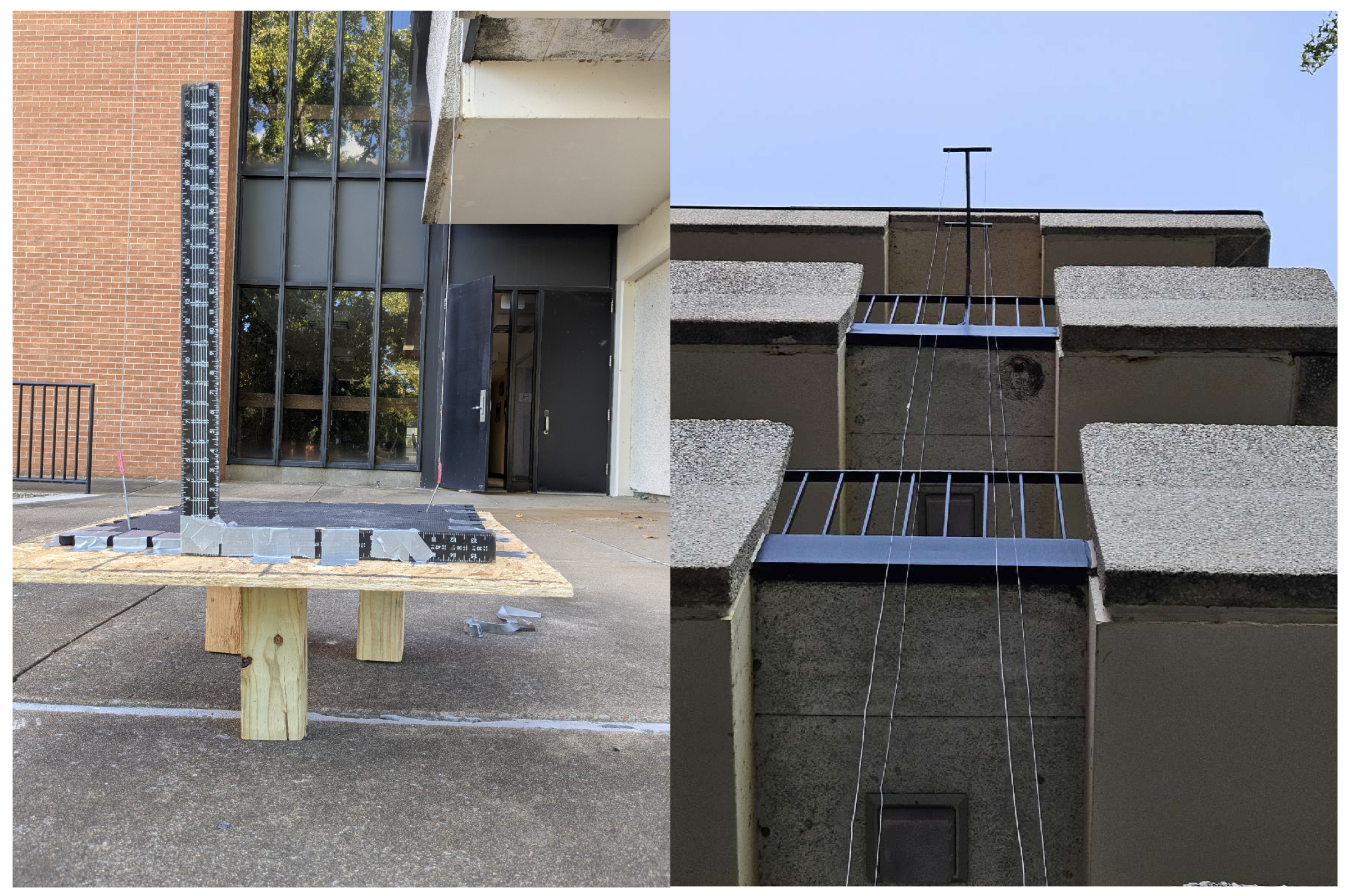
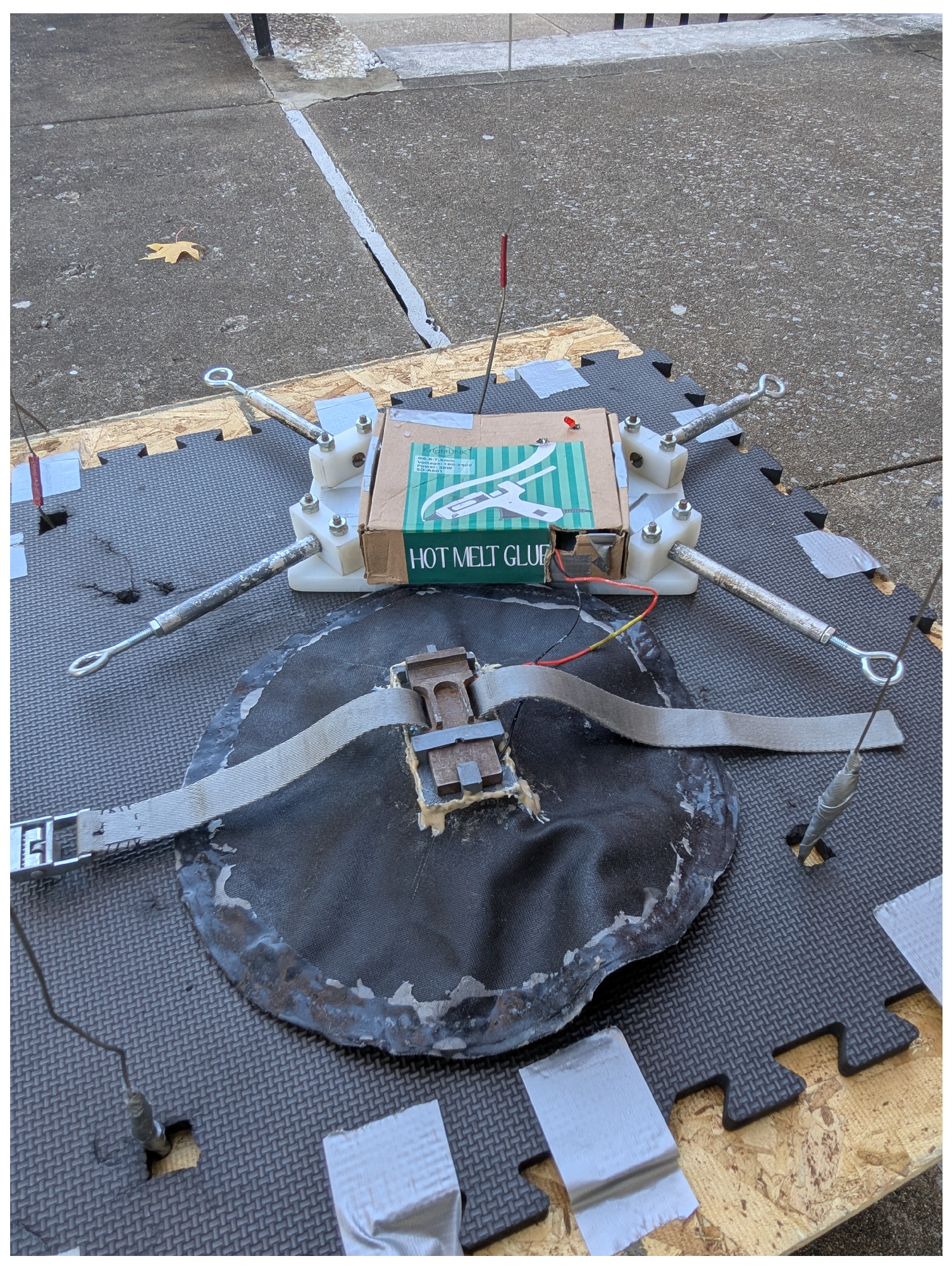
Forty feet above the testing platform, the guide wires are attached to the steel frame and then the platform below as shown in Figure 18. The steel frame and guide wire system used for this research is the same frame used within Hettel’s thesis paper, with a few adjustments, and more information on it can be found within his paper [32]. The steel frame was extended so that each of the guide wires can not interfere with the UAV or airbag as it drops. The frame and guide wires are used to ensure that the UAV is guided to the impact platform as it drops and the airbag deploys. A small testing platform at the bottom gives the guide wires a solid point to hook into so they remain taut, and a softer platform for impact so the dummy UAV can be used for multiple tests. Along one edge of the test platform is a height gauge, so that the rebound after impact can be measured for the total elasticity and energy loss of the impact. Because the drop testing attachment point was around 40 ft above the testing platform the circuit system was able to detect the drop and inflate before reaching the testing platform. After attaching the dummy UAV to the guide wires, the barometer reads the current height as 12.3 m, providing just enough fall time to detect both conditions and trigger the airbag. Since there is around 0.3 m of travel distance between the drop height and threshold height, there were no false deployments outside of human error, like dropping the dummy UAV while attaching the guide wires.
The frame that holds the guide wires hangs over the ledge of a fourth floor balcony while the testing platform rests below it. Each of the guide wires are attached to the testing platform by hooking onto it, so that the lines remain taught and the dummy UAV drops straight down. Because the drop test equipment only requires the frame, guide wires, and platform, there is not much else set up before testing or between tests.
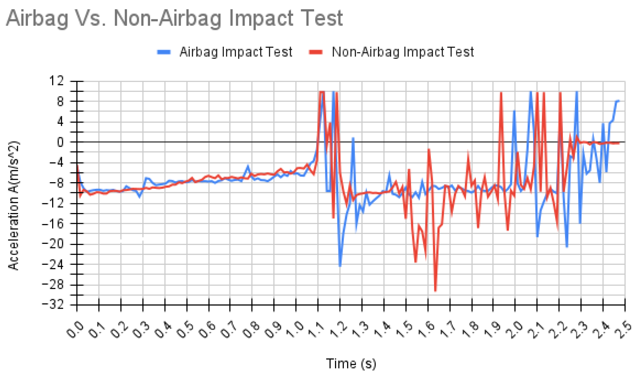
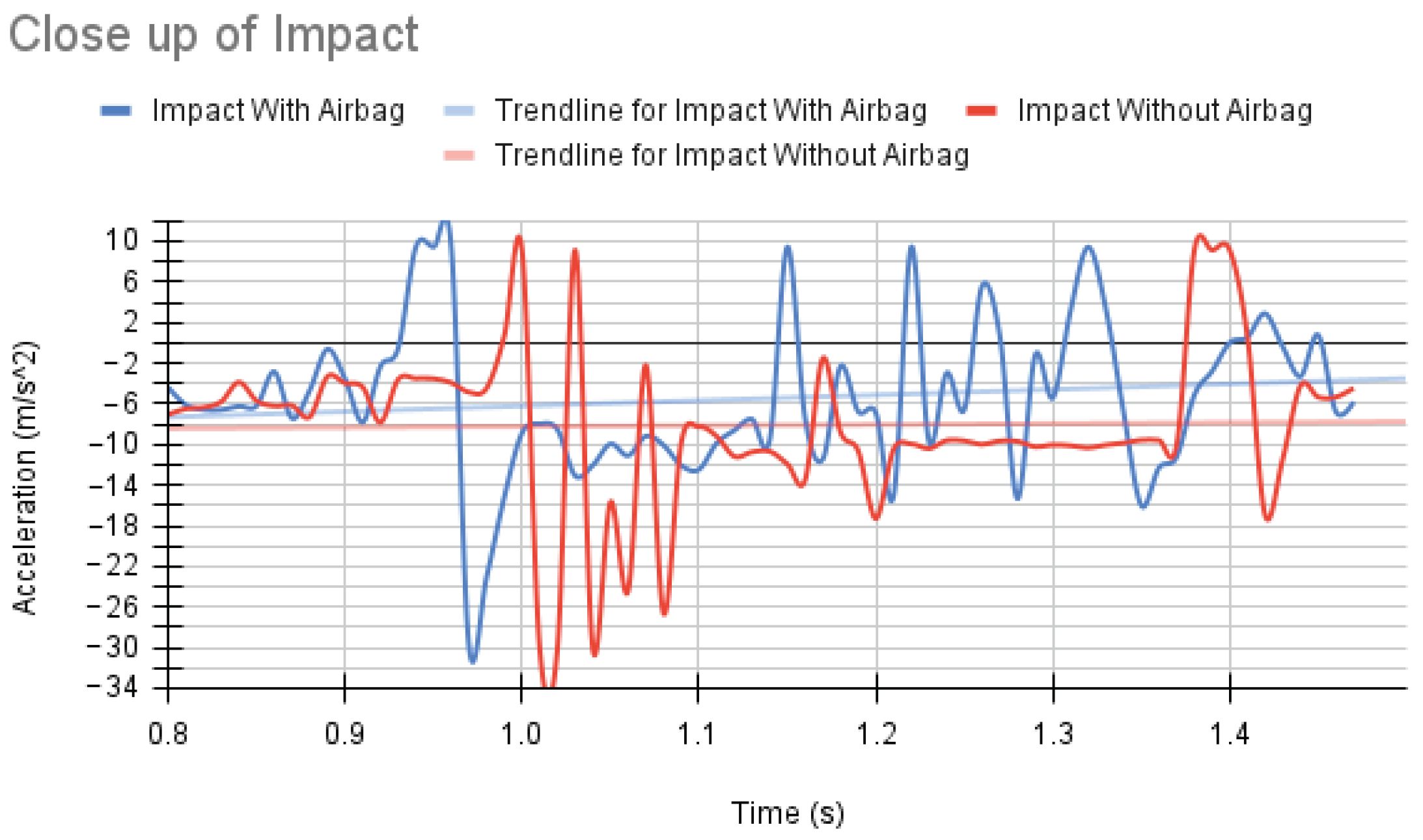
Six different tests were performed that recorded the acceleration from various perspectives. Figure A13 records the acceleration experienced by a spring platform underneath the UAV and shows the difference between with and without the airbag. Figure A14 is a separate test that still uses the spring platform and instead records the acceleration experienced by the UAV during the impact. Each of these tests prove the main theory that the acceleration and impact force is reduced when using the airbag safety system. For each of these tests, around 150 samples were collected from the acceleration experienced by the UAV during the fall and impact. From these tests, the average acceleration experienced by the airbag impact tests was −6.77 m/s2 and the non airbag acceleration was −7.48 m/s2. The standard deviation of the airbag impact tests was found to be 5.34, and the non airbag was 5.65. With each of these, the confidence interval of the airbag and non airbag impact tests can be calculated. With 95% confidence, the acceleration during impact of the UAV with the airbag is between −5.89 and −7.64 m/s2 and the non airbag acceleration during impact is between −6.56 and −8.41 m/s2. Thus the airbag system greatly reduces the experienced by the UAV during impact. As with any experimentation, there are a number of uncertainties that arise. For this experiment, just a single accelerometer provided uneven results and was not quite exact, which is why a second accelerometer was added, and the acceleration experienced by the UAV was the average of both to remove outliers and odd readings. Another uncertainty that arises is the weather itself. As this is a drop test, the strength of the wind can directly effect how the UAV impacts the platform and how it lands. Each of the tests were performed at the most ideal conditions possible, but strong gusts of wind were unfortunately unavoidable.
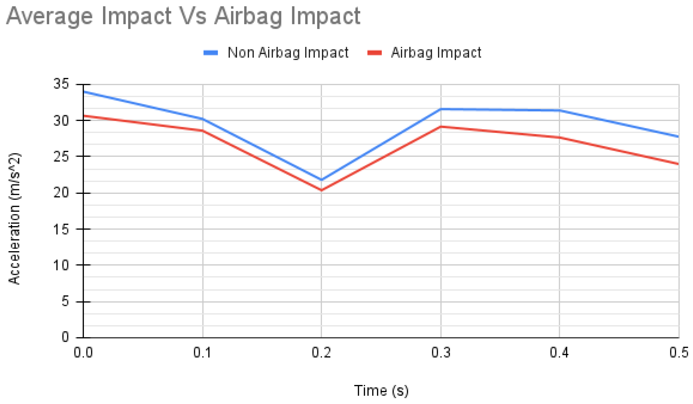
When comparing the acceleration experienced by the UAV, it can be observed in Figure 19 that the airbag greatly reduced the maximum negative acceleration the UAV incurs during impact. The height gained by each test also varied greatly; because the airbag collision was more elastic it rebounded much more than the non airbag impact. Meanwhile, the non airbag test was much less elastic and only rebounded around 0.533 m. Using the rebound height, weight of the UAV, and potential energy we can determine the energy lost through the collision and the elasticity. Equations (6)–(9) detail the energy loss in each collision, and Equation (10) calculates the impact force with and without the airbag. The h in Equation (7) is the height the UAV rebounds to after the impact. Equations (6)–(11) all come from the Engineering Mechanics: Dynamics book Ed. 7 on the impact force of a falling object [33]. For simplicity, these equations ignore other resistive forces to determine the impact force. The collision distance in Equation (11) is set to 0.127 m, because that is the height of the airbag when fully inflated. In the case of the non airbag impact, the collision distance of 0.025 m is used again from before.
Velocity of Approach = 2 g h V 1 = 2 9.8 12.2 V 1 = 15.46 m / s
Velocity after Impact with Airbag V 1 = 2 g h V 1 = 2 9.8 0.914 V 1 = 4.23 m / s Velocity after Impact without Airbag V 1 = 2 g h V 1 = 2 9.8 0.533 V 1 = 3.23 m / s
Conservation of Momentum with Airbag m V 1 + 0 = m V 1 + m V 2 1.66 15.46 + 0 = 1.66 4.23 + 9 V 2 25.66 = 7.02 + 9 V 2 V 2 = 3.63 m / s Conservation of Momentum without Airbag m V 1 + 0 = m V 1 + m V 2 0.97 15.46 + 0 = 0.97 3.23 + 9 V 2 14.99 = 3.13 + 9 V 2 V 2 = 2.01 m / s
Energy just after Impact with Airbag T = 0.5 m V 1 2 + 0.5 m V 2 2 T = 0.5 1.66 4 . 23 2 + 0.5 9 3 . 63 2 T = 74.15 J Energy just after Impact without Airbag T = 0.5 m V 1 2 + 0.5 m V 2 2 T = 0.5 0.97 3 . 23 2 + 0.5 9 2 . 01 2 T = 23.24 J
Energy Loss with Airbag = ( ( P E T ) / P E ) 100 Energy Loss = ( 198.47 74.15 ) / 198.47 ) 100 Energy Loss = 62.64 % Energy Loss without Airbag = ( ( P E T ) / P E ) 100 Energy Loss = ( 115.97 23.24 ) / 115.97 ) 100 Energy Loss = 79.96 %
Impact Force with Airbag = K E / s Impact Force with Airbag = 198.47 / 0.127 Impact Force with Airbag = 1562.76 N Impact Force without Airbag = K E / s Impact Force without Airbag = 115.97 / 0.025 Impact Force without Airbag = 4638.8 N
As seen in Equations (6)–(10), the impact without the airbag loses around 17% more energy during its collision. This means that more energy is being lost to the surroundings as the impact occurs. In the case of the non-airbag collision, only the UAV and the testing platform are impacted; so, the majority of the force is going into one or the other. However, when an airbag is introduced, less energy is lost in the impact, as the airbag absorbs some of the impact force during the impact. Equation (10) details how the impact distance also changes the overall force experienced. With a 4 inch airbag, the distance of impact is greatly increased, and the amount of force is reduced. Recall from earlier that the human skull can withstand forces between 1779.29 and 4893.04 N. When an airbag is included, the force is lowered from 4638.8N to 1562.76N, which would still hurt but does protect the person below the UAV.
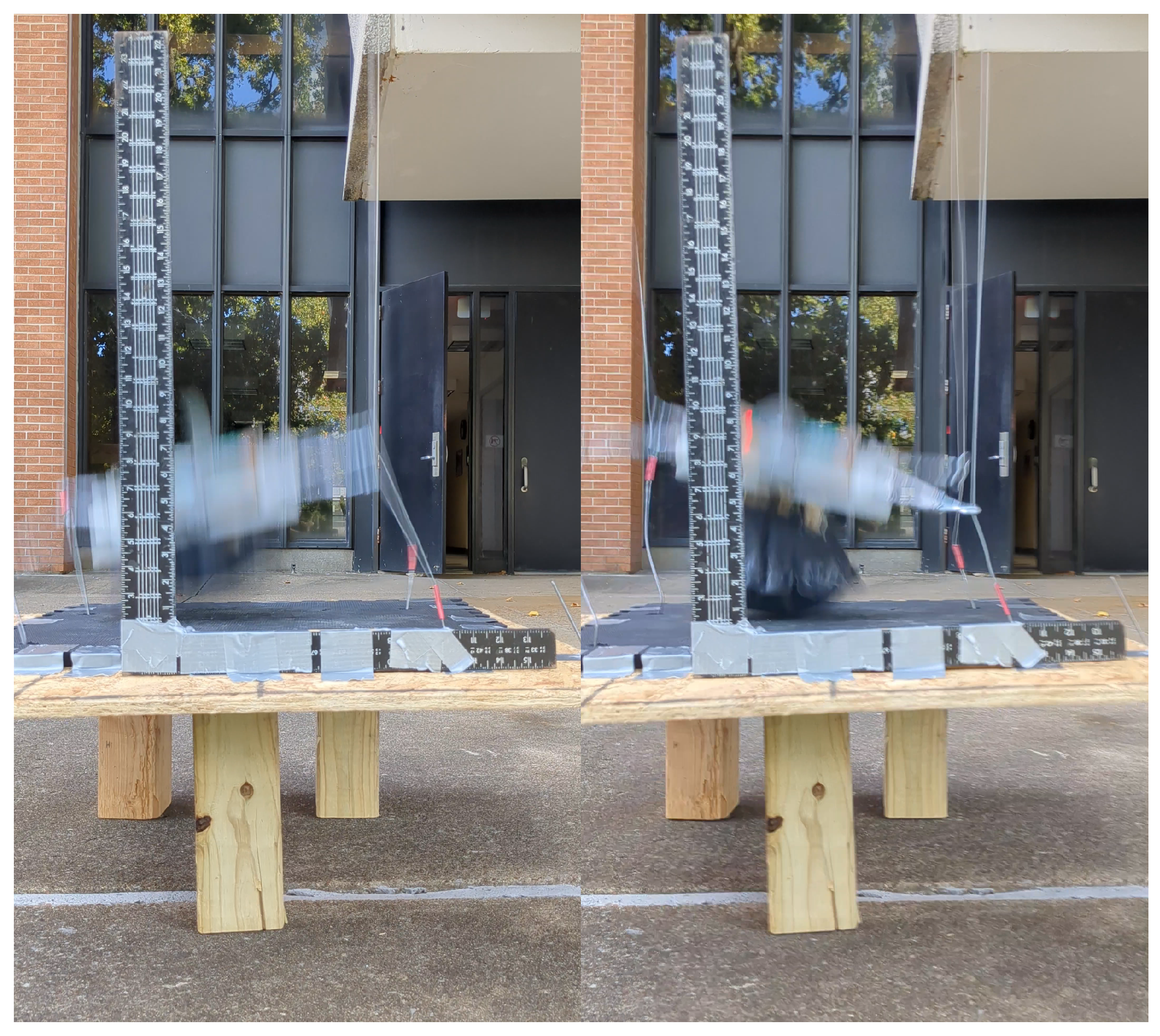
Another parameter to look at as well is the deployment time of the safety system. In Cawthorne’s [6] paper, the time it took to deploy the airbag was around 2 s. Since this system is designed to automatically deploy while falling, it can deploy in the 1.5 s before it impacts the testing platform. But when taking a closer look at how the system reacts, Figure 20 shows the UAV two frames before impact.The left side depicts the UAV just before it impacts the platform, as the system is on and working to trigger the inflation. The right side is one frame later, as the airbag is fully inflated just before the UAV collides with the platform. This video is recorded at 30 FPS, meaning that the time between each frame is 0.033 s. This means that the system can automatically respond to a free-fall rapidly and fully deploy the airbag in less than a second, and the airbag itself only takes 0.033 s to inflate.

4. Discussion

This research shows that the proposed airbag safety system for a UAV can reduce the impact force during a collision and protect anything or anyone below it. The use of a barometer and accelerometer makes the safety system entirely autonomous, and the black powder inflation method reduces the time needed to fully inflate the airbag. With a quick way to attach the system as well, it can be scaled up or down as needed and attached to almost any UAV for protection.
Of course, a safety system like this also has its own limitations as well. This system is designed for in-flight use; so, it does not provide much protection during the launch or landing of the UAV. On top of this, there is always a concern about the rebound after the airbag impact and potentially colliding with another person and doing more damage. This issue can be mitigated by limiting the degree of airbag inflation to prevent excessive internal pressure during impact by using less black powder. In addition, as a suggestion for future work, design modifications specifically intended to minimize the rebound forces may offer a more effective solution. The system did prove quite reliable, as long as the black powder was kept dry, and the system was initialized properly; resting on the ground and undisturbed, the airbag system triggered properly each time.
Although the safety system is proven to work, there are a number of ways to improve upon it. The overall weight of the system ended up much higher than expected in the end. The total weight of the airbag system that attached to the UAV is 0.7 kg, and with a Mavic Air 2 that only weighs 0.57 kg, that ends up being over 120% of the UAVs weight. Even though this safety system is heavier than the UAV currently, it can still carry it properly, as the Mavic Air 2 has a carrying capacity of 0.83 kg. This ensures that even though the safety system is quite heavy, the UAV is still able to support it in flight. As more developments are made to decrease the overall weight of the system, the hindrance of the airbag system can be reduced. Improvements can be made to this system by reducing the weight of the snap or protection plate, reducing the weight of the detonator shell, changing the airbag material to something lighter but just as strong, or increasing the airbag size. In an attempt to reduce the weight of the protection plate, a 3D-printed model was used. This produced a noticeable change in weight, as the steel version of the protection plate weighed 171.9 g, while the nylon variant weighed 15.4 g. This is a sizable decrease in weight, but we were not able to produce an evenly flat nylon plate, as the protection plate was warped by the cooling process of the nylon. Therefore, during the impact, certain areas of the drone would incur more stress than others. Due to this, the decision to remain with steel was made to ensure it was perfectly flat, add extra weight to the bottom of the UAV to ensure the airbag side remained facing the ground, and guarantee the re-usability of the part. As the airbag system is optimized to reduce weight and increase the airbag size, the effectiveness of the safety system increases, as the energy loss is decreased and the impact force is lowered. A valid concern of this research could be the use of an explosive material on a UAV; however, as long as the safety system is approved by the FAA as a valid safety system, then it should be fine to fly with. Furthermore, since the black powder used to inflate the airbag is completely sealed with the detonator shell, there is no risk of the flammable material escaping the airbag system, even if the airbag is punctured or torn.

Supplementary Materials

The following supporting information can be downloaded at https://www.mdpi.com/article/10.3390/drones10030199/s1, Included with the submission file is a video of testing that shows the safety system in use on the testing system. The video titled “Drop test Video” demonstrates how the safety system would normally work when plummeting from that height or higher.

Author Contributions

Conceptualization, H.E.; methodology, investigation, B.V. and H.E.; writing—original draft preparation, writing—review and editing, B.V. and H.E.; supervision, project administration, H.E. All authors have read and agreed to the published version of the manuscript.

Funding

This research is partially funded by Southern Illinois University Carbondale.

Data Availability Statement

The data presented in this study are available on request from the corresponding author.

Conflicts of Interest

The authors declare no conflicts of interest.

Appendix A

Figure A1. Cross -section view of Disney’s airbag design [14].
Drones 10 00199 g0a1
Figure A2. Shape of a cylindrical airbag under impact [7].
Drones 10 00199 g0a2
Figure A3. Shape of a truncated pyramid airbag under impact [7].
Drones 10 00199 g0a3
Figure A4. Truncated square airbag design.
Drones 10 00199 g0a4
Figure A5. Truncated octagon airbag design.
Drones 10 00199 g0a5
Figure A6. Detonator shell and lid.
Drones 10 00199 g0a6
Figure A7. Detonator shell closed with lid.
Drones 10 00199 g0a7
Figure A8. Protection plate from above.
Drones 10 00199 g0a8
Figure A9. Snap plate from above.
Drones 10 00199 g0a9
Figure A10. Dummy UAV and airbag side by side.
Drones 10 00199 g0a10
Figure A11. Circuit box when closed.
Drones 10 00199 g0a11
Figure A12. Inside of circuit box.
Drones 10 00199 g0a12
Figure A13. Impact acceleration from ground POV.
Drones 10 00199 g0a13
Figure A14. Impact acceleration from UAV POV.
Drones 10 00199 g0a14

References

  1. Carter, C. I’m the Site Lead at One of Amazon’s First Drone Delivery Sites. Here Are 6 Cool Facts About Our Operations in Texas. Amazon News, 1 April 2024.
  2. Federal Aviation Administration. Drones by the Numbers (as of August 2024). 2024. Available online: https://www.faa.gov/node/26 (accessed on 15 August 2025).
  3. FAA. Emerging Aviation Entrants: Unmanned Aircraft System and Advanced Air Mobility; FAA: Washington, DC, USA, 2023.
  4. Drone Tech. Causes of UAV Loss. Drone Tech, 2022. Available online: https://www.dronetechuav.com/_files/ugd/f90caa_99737d44a3bb4205b37a982cfaa1712e.pdf (accessed on 15 August 2025).
  5. Ansari, K.; Shendge, A.; Pakhrani, K.; Singh, R. Design and development of an auto-inflatable airbag as the failsafe system of unmanned aerial vehicle. Mater. Today Proc. 2023, 77, 983–990. [Google Scholar] [CrossRef] [Scilit]
  6. Cawthorne, D. Development of a Multirotor Drone Airbag. Ph.D. Thesis, SDU Unmanned Aerial Systems Center, Institute for Technology and Innovation, Odense, Denmark, 2016. [Google Scholar]
  7. Alizadeh, M.; Sedaghat, A.; Kargar, E. Shape and Orifice Optimization of Airbag Systems for UAV Parachute Landing. Int. J. Aeronaut. Space Sci. 2014, 15, 335–343. [Google Scholar] [CrossRef] [Scilit]
  8. Zhou, X.; Zhou, S.; Li, D. Optimal Design of Airbag Landing System without Rebound. IOP Conf. Ser. Mater. Sci. Eng. 2019, 531, 012001. [Google Scholar] [CrossRef] [Scilit]
  9. Mueller, B. Airbags. IIHS, 2023. Available online: https://www.iihs.org/research-areas/airbags (accessed on 5 October 2024).
  10. DoT. Airbag Basics. CT.gov, 2023. Available online: https://portal.ct.gov/dot/pp_policy/documents/air-bag-basics?language=en_US (accessed on 1 October 2024).
  11. Frank. How Does a Vehicle Airbag Work? Lab Supply Network, 26 November 2019.
  12. Halford, B. What chemicals make airbags inflate, and how have they changed over time? Chemical and Engineering News, 15 November 2022.
  13. Wendt, M. Safety Data Sheet-Black Powder. 2014. Available online: https://goexpowder.com/wp-content/uploads/2018/05/sds-sheets-goex-black-powder.pdf (accessed on 15 July 2025).
  14. Wong, C. Impact Absorption Apparatus for Unmanned Aerial Vehicle. U.S. Patent US20160332739A1, 17 November 2016. [Google Scholar]
  15. Loeb, W. Amazon’s Drones Are Grounded. Forbes, 2 February 2023.
  16. Lavars, N. Amazon to begin testing new delivery drones in the US. New Atlas, 13 April 2015.
  17. Snyder, P. The Science of Skull Fracture. Explico, 2021. Available online: https://www.explico.com/post/the-science-of-skull-fracture (accessed on 1 November 2024).
  18. Impact Forces Acting on Falling Objects Hitting the Ground, Cars Crashing and Similar Cases. Engineering Toolbox, 2011. Available online: https://www.engineeringtoolbox.com/impact-force-d_1780.html (accessed on 5 September 2025).
  19. Edwards, C. Amazon’s giant new ‘super drone’ delivers packages to your door shockingly fast—But has a frustrating catch. The US Sun, 11 November 2022.
  20. Fruity Chutes Inc. DJI Mavic 2 Parachute with Sentinel Automatic Trigger System. 2012. Available online: https://shop.fruitychutes.com/products/dji-mavic-2-parachute-with-sentinel-automatic-trigger-system?srsltid=AfmBOorH5CLR9Yz4CSeBTpF9vOXv6PAWdzbcnET4sX8M35DYfzM2gBUx (accessed on 15 October 2024).
  21. Kumar, R.; Singh, J.; Yadav, P.; Semwal, N.; Yadav, S.; Bhorey, A.; Bhaumik; Dhawan, H. Parachute deployment system for safe recovery of a drone. Mater. Today Proc. 2023. [Google Scholar] [CrossRef] [Scilit]
  22. García-Beltrán, C.; Miranda-Araujo, E.; Guerrero-Sanchez, M.; Valencia-Palomo, G.; Hernández-González, O.; Gómez-Peñate, S. Passivity-based control laws for an unmanned powered parachute aircraft. Asian J. Control 2021, 23, 2087–2096. [Google Scholar] [CrossRef] [Scilit]
  23. Beliautsou, V.; Beliautsou, A. Prop-plane — New convertible VTOL UAV as a combination of a longitudinal bicopter and a flying wing with a tilt-rotor powertrain. Aerosp. Sci. Technol. 2024, 155, 109650. [Google Scholar] [CrossRef] [Scilit]
  24. Farajijalal, M.; Eslamiat, H.; Avineni, V.; Hettel, E.; Lindsay, C. Safety Systems for Emergency Landing of Civilian Unmanned Aerial Vehicles (UAVs)—A Comprehensive Review. Drones 2025, 9, 141. [Google Scholar] [CrossRef] [Scilit]
  25. Midmountain. Specialty airbag fabrics and their military applications. Mid-Mountain Materials, 9 November 2018.
  26. ASTM D5035-11; Standard Test Method for Breaking Force and Elongation of Textile Fabrics (Strip Method). ASTM International: West Conshohocken, PA, USA, 2019. [CrossRef] [Scilit]
  27. Hall, N. Motion of Free Falling Object. 2025. Available online: https://www1.grc.nasa.gov/beginners-guide-to-aeronautics/motion-of-free-falling-object/ (accessed on 9 September 2024).
  28. Brown, M.E.; Rugunanan, R.A. A temperature-profile Study of the Combustion of Black Powder and its constituent binary mixtures. Propellants Explos. Pyrotech. 1989, 14, 69–75. [Google Scholar] [CrossRef] [Scilit]
  29. McClements, D.; Zidonis, A. Nylon: Uses, Types, and Materials. Xometrys RSS, 2025. Available online: https://www.xometry.com/resources/materials/nylon/#:~:text=The%20tenacity%20of%20nylon%206,C%20(302%20ÂřF (accessed on 12 September 2025).
  30. CRE CHEM NEWS. The Chemistry Behind Sodium Bicarbonate’s Role in Fire Extinguishers and Industrial Applications. Credit, 9 May 2025.
  31. Elastostar. Silicone Rubber Temperature: How Much Heat Can It Withstand? Elastostar Rubber Corporation, 2024. Available online: https://elastostar.com/silicone-rubber-temperature-how-much-heat-can-it-withstand/ (accessed on 3 March 2025).
  32. Hettel, E.J.; Eslamiat, H.; Aleemuddin, M.; Farajijalal, M. Assessing Head Injury of Civilian UAV Safety Systems: A Test Apparatus and Spherical Shell Example. IEEE Access 2025, 13, 136598–136611. [Google Scholar] [CrossRef] [Scilit]
  33. Meriam, J.L.; Kraige, L.G. Kinematics of Particles—Special Applications. In Engineering Mechanics Dynamics, 7th ed.; John Wiley & Sons, Inc.: Hoboken, NJ, USA, 2012; Volume 2, pp. 217–221. [Google Scholar]
Figure 1. Airbag inflation method [11].
Drones 10 00199 g001
Figure 2. Amazon MK27 [19].
Drones 10 00199 g002
Figure 3. 0.5 kg UAV impact results with an airbag, adapted and edited to enhance quality from [5].
Drones 10 00199 g003
Figure 4. 0.5 kg UAV impact results without an airbag, adapted and edited to enhance quality from [5].
Drones 10 00199 g004
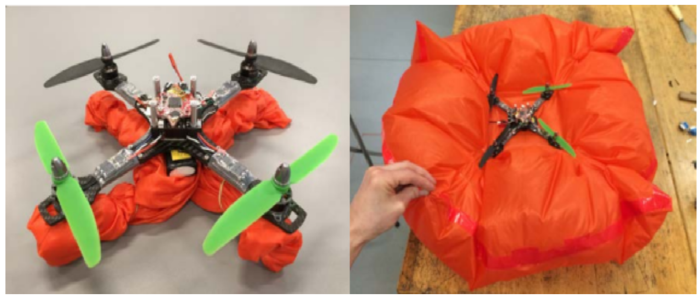
Figure 5. 0.35 kg UAV with airbag attached, set up and post deployment [6].
Drones 10 00199 g005
Figure 6. Nylon 6 stress–strain graph.
Drones 10 00199 g006
Figure 7. Truncated square CAD design.
Drones 10 00199 g007
Figure 8. Truncated octagon CAD design.
Drones 10 00199 g008
Figure 9. Flowchart of how autonomous system functions.
Drones 10 00199 g009
Figure 10. Wiring diagram of the proposed airbag circuit.
Drones 10 00199 g010
Figure 11. Estes rocket charge.
Drones 10 00199 g011
Figure 12. Detonator shell interior.
Drones 10 00199 g012
Figure 14. Protection and snap plate from side.
Drones 10 00199 g014
Figure 15. Attachment system of airbag to UAV.
Drones 10 00199 g015
Figure 16. Circuit box on UAV.
Drones 10 00199 g016
Figure 17. Exploded view of system.
Drones 10 00199 g017
Figure 18. Impact platform and guide wire system.
Drones 10 00199 g018
Figure 19. Airbag vs. Non-Airbag Impact Test.
Drones 10 00199 g019
Figure 20. UAV; two frames before impact.
Drones 10 00199 g020
Table 1. Common citations in the Introduction.
ReferenceYear PublishedVehicle TypeAirbag TypeInflation MethodKey Information
Ansari [5]2022Multi-rotor UAVSquare, only on bottom of UAVPressurized air canisterThesis written on the design and use of a UAV airbag to reduce the stress taken upon impact by the UAV. By comparing the stress of a UAV with and without an airbag, the effectiveness of an airbag system is demonstrated. The design of this airbag used a simple square shape larger than the area of the UAV to protect the bottom of the UAV as it falls. This lends credence to the research as the simulated effects of an airbag system can be measured.
Cawthorne [6]2016Multi-rotor UAVHexagon, only used on bottom of UAVPressurized air canisterThesis about the design of a lightweight airbag system used to increase drag of a falling UAV and decrease kinetic energy before and during impact. This is shown by comparing the impact energy and impact velocity with and without the airbag system. The design of the airbag uses an airbag on the bottom of the UAV and is a hexagonal shape larger than the UAVs area. This paper is important to compare the effectiveness of the airbag system and demonstrate a non-chemically inflated airbag.
Frank [11]2019CarStandard balloon shape used in carsChemical reactionAn article about how a car’s airbag is deployed and the process of such. When the car’s sensors detect a collision, a small electrical signal is sent to the airbag system that ignites the chemical used to inflate the airbag within 0.03 s. The chemical discussed is sodium azide, which when heated, produces nitrogen in an explosive fashion. The main basis of this paper is a chemically inflated airbag, which is used primally in cars; this article details how the car airbag inflates and what chemicals are used.
Halford [12]2022NANAChemical reactionAn article discussing guanidine nitrate and its use in car airbags. The article details the chemical properties of guanidine nitrate and the reaction that takes place once an electrical current is used to heat the chemical. It also compares the toxicity of guanidine nitrate and sodium azide, both of which are used in car airbags. Sodium azide is much more reactive and dangerous to handle, which makes guanidine nitrate a much safer choice to use. This is another paper on chemicals used in chemically inflated airbags and how that process takes place, which is necessary for determining how to design an airbag for a UAV.
Wong [14]2016Multi-rotor UAVDoughnut, both on top and on bottomPressurized air canisterPatent filed for a doughnut-shaped airbag that fully engulfs the UAV to protect both the UAV and objects underneath it. The design of this system uses two separate airbags, on the top and bottom of the UAV to fully protect the UAV during its fall. This is accomplished by using an altimeter to determine the current height, and if the UAV falls below a preset safe height, the air canister will inflate both the top and bottom airbags on the UAV. This patent also details the deployment detection system and when the autonomous system activates.
Zhou [8]2019Multi-rotor UAVLongitudinal cylinder, only used on the bottom of the UAVPressurized air canisterThesis is based on the optimal pressure-relieving vent size based on airbag size. A cylindrical airbag of various lengths and diameters is used as a basis to compare a set number of vent sizes. Each combination is then compared against each other to determine the most effective and how much influence each change has on the design. This is accomplished by comparing the impact acceleration, touchdown speed, and internal pressure upon impact.
Table 3. Trigger condition of airbag system.
Height (m)Acceleration (m/s2)Trigger Condition
16−9.8YES. The height is above the threshold and acceleration is at the threshold.
17−5.6NO. While the height is correct, the acceleration isn’t fast enough.
10−9.8NO. The acceleration is correct, but it is below the height threshold.
Table 4. Weight breakdown of airbag system.
System PartWeight (kg)
Airbag0.14
Detonator Shell0.18
Gas Generator0.02
Circuit System0.16
Protection and Snap Plate0.2
Total Weight of System0.7
3D-printed Protection Plate0.015
New Total with 3D-printed parts0.544
Disclaimer/Publisher’s Note: The statements, opinions and data contained in all publications are solely those of the individual author(s) and contributor(s) and not of MDPI and/or the editor(s). MDPI and/or the editor(s) disclaim responsibility for any injury to people or property resulting from any ideas, methods, instructions or products referred to in the content.