
Vibration Emissions of Grinders: Experiments and a Model †


Abstract
1. Introduction
2. Materials and Methods
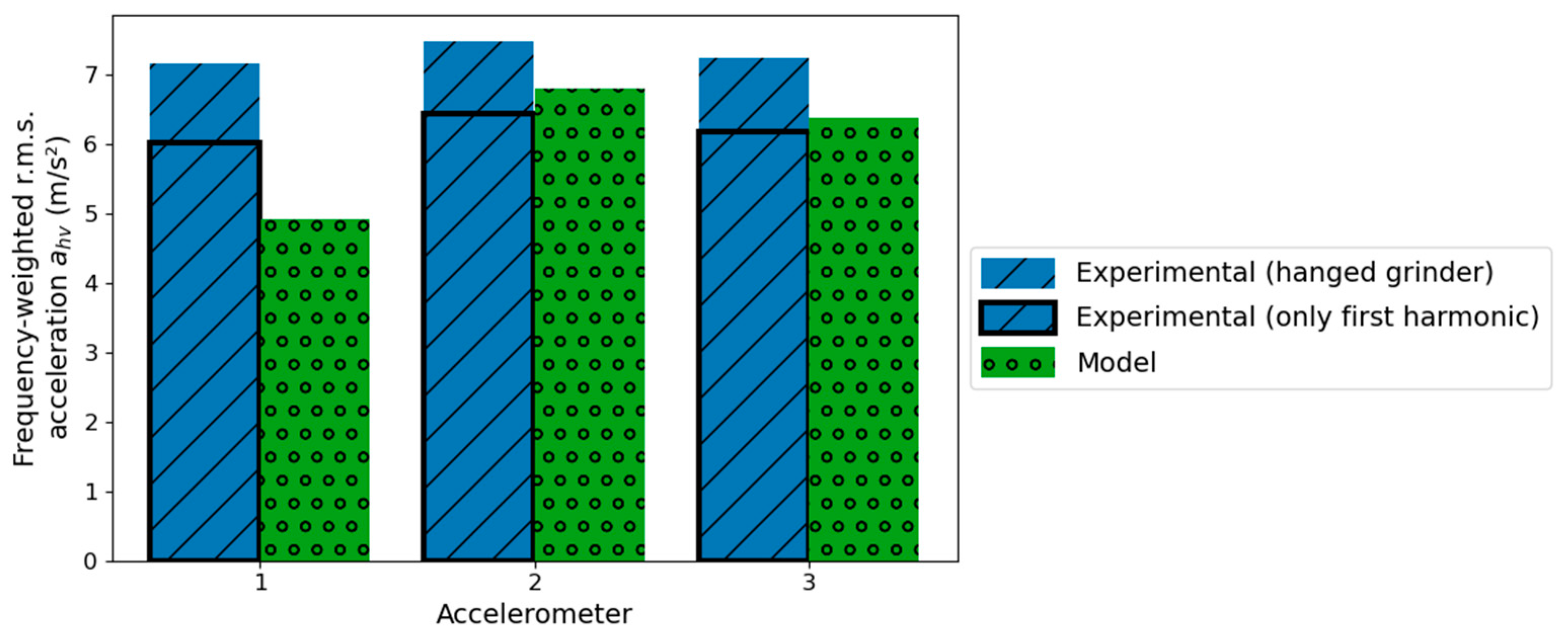
3. Numerical Model
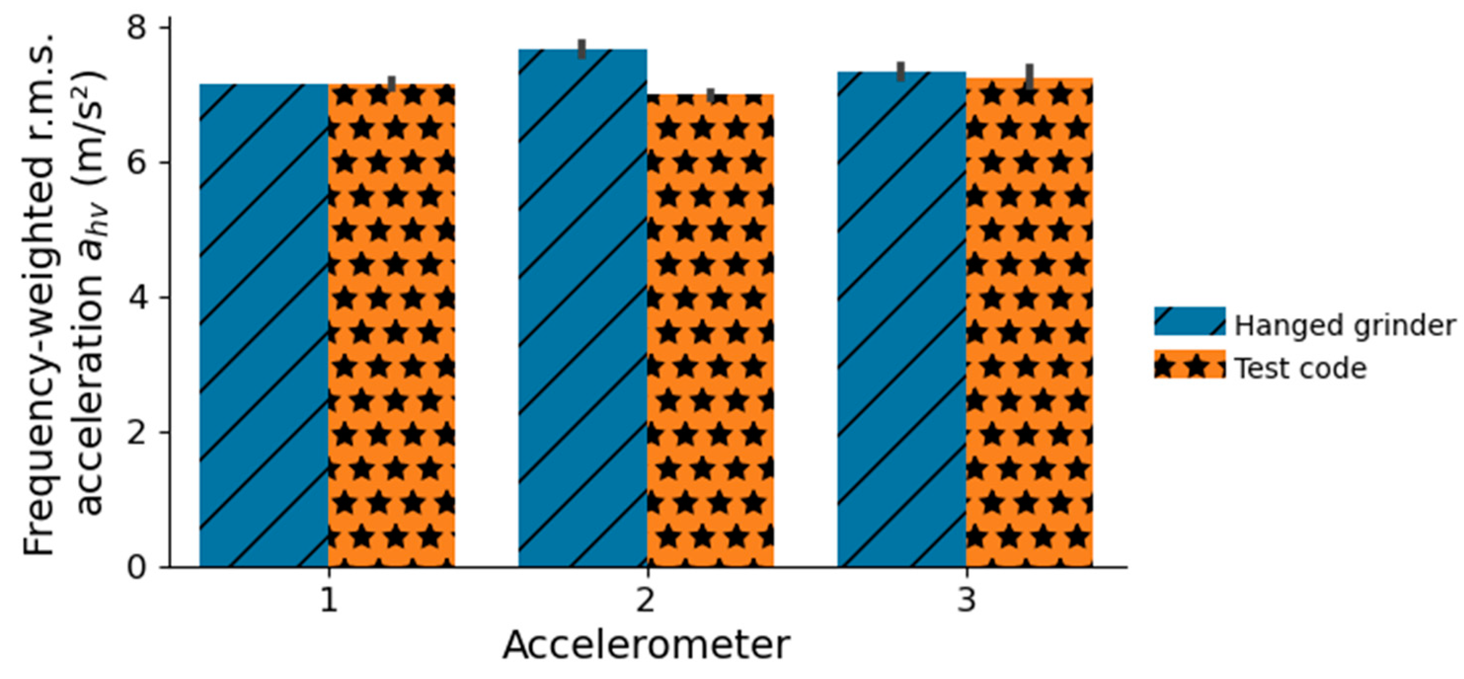
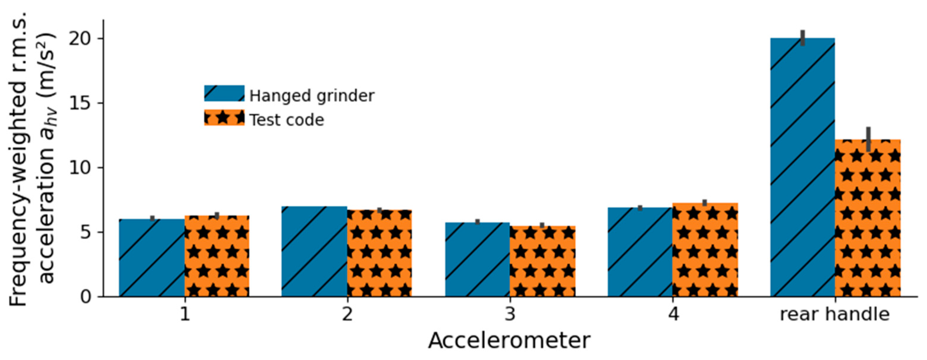
4. Results
5. Discussion
6. Conclusions
Funding
Institutional Review Board Statement
Informed Consent Statement
Data Availability Statement
Conflicts of Interest
References
- ISO 5349-1:2001; Mechanical Vibration—Measurement and Evaluation of Human Exposure to Hand-Transmitted Vibration—Part 1: General Requirements. International Organization for Standardization: Geneva, Switzerland, 2001.
- Mirbod, S.M.; Inaba, R.; Iwata, H. A Study on the Vibration-Dose Limit for Japanese Workers Exposed to Hand-Arm Vibration. Ind. Health 1992, 30, 1–22. [Google Scholar] [CrossRef] [PubMed]
- Burström, L.; Lundström, R.; Hagberg, M.; Nilsson, T. Comparison of Different Measures for Hand–Arm Vibration Exposure. Saf. Sci. 1998, 28, 3–14. [Google Scholar] [CrossRef]
- Jang, J.-Y.; Kim, S.; Park, S.K.; Roh, J.; Lee, T.-Y.; Youn, J.T. Quantitative Exposure Assessment for Shipyard Workers Exposed to Hand-Transmitted Vibration From a Variety of Vibration Tools. AIHA J. 2002, 63, 305–310. [Google Scholar] [CrossRef] [PubMed]
- Rimell, A.N.; Notini, L.; Mansfield, N.J.; Edwards, D.J. Variation between Manufacturers’ Declared Vibration Emission Values and Those Measured under Simulated Workplace Conditions for a Range of Hand-Held Power Tools Typically Found in the Construction Industry. Int. J. Ind. Ergon. 2008, 38, 661–675. [Google Scholar] [CrossRef]
- Edwards, D.J.; Rillie, I.; Chileshe, N.; Lai, J.; Hosseini, M.R.; Thwala, W.D. A Field Survey of Hand–Arm Vibration Exposure in the UK Utilities Sector. Eng. Constr. Archit. Manag. 2020, 27, 2179–2198. [Google Scholar] [CrossRef]
- Lemerle, P.; Klingler, A.; Trompette, N.; Cristalli, A.; Geuder, M. Development and Validation of an Accurate Testing Procedure to Measure Coupling Forces and Characterize the Man/Machine Interaction. In Proceedings of the 11th International Conference on Hand-Arm Vibration, Bologna, Italy, 3–7 June 2007; pp. 3–7. [Google Scholar]
- Liljelind, I.; Pettersson, H.; Nilsson, L.; Wahlström, J.; Toomingas, A.; Lundström, R.; Burström, L. Determinants Explaining the Variability of Hand-Transmitted Vibration Emissions from Two Different Work Tasks: Grinding and Cutting Using Angle Grinders. Ann. Occup. Hyg. 2013, 57, 1065–1077. [Google Scholar] [PubMed]
- EN 60745-2-3:2011; Hand-Held Motor-Operated Electric Tools—Safety—Part 2-3: Particular Requirements for Grinders, Polishers and Disk-Type Sanders. CENELEC: Brussels, Belgium, 2011.


Disclaimer/Publisher’s Note: The statements, opinions and data contained in all publications are solely those of the individual author(s) and contributor(s) and not of MDPI and/or the editor(s). MDPI and/or the editor(s) disclaim responsibility for any injury to people or property resulting from any ideas, methods, instructions or products referred to in the content. |
© 2023 by the author. Licensee MDPI, Basel, Switzerland. This article is an open access article distributed under the terms and conditions of the Creative Commons Attribution (CC BY) license (https://creativecommons.org/licenses/by/4.0/).
Share and Cite
Pierron, Q. Vibration Emissions of Grinders: Experiments and a Model. Proceedings 2023, 86, 13. https://doi.org/10.3390/proceedings2023086013
Pierron Q. Vibration Emissions of Grinders: Experiments and a Model. Proceedings. 2023; 86(1):13. https://doi.org/10.3390/proceedings2023086013
Chicago/Turabian StylePierron, Quentin. 2023. "Vibration Emissions of Grinders: Experiments and a Model" Proceedings 86, no. 1: 13. https://doi.org/10.3390/proceedings2023086013
APA StylePierron, Q. (2023). Vibration Emissions of Grinders: Experiments and a Model. Proceedings, 86(1), 13. https://doi.org/10.3390/proceedings2023086013