1. Introduction
E-textiles are gaining popularity as the electronics sector is developing fast, with components getting smaller and more affordable. Smart electronics can be integrated into textile-based products without compromising their comfort. This is why the textile industry has an increasing interest in exploring E-textiles. Bringing electronics and textiles together can be challenging, costly and slow though, as the two industries differ in many areas.
As part of the Textile Prototyping Lab (TPL) [
1]—an open-innovation platform for high-tech textiles—a modular E-textiles toolkit was conceived and developed to provide easy access to textile-integrated electronics development. In particular, small- and medium-sized enterprises (SMEs) from the textile industry can benefit from the toolkit, as they often lack the necessary multidisciplinary know-how and resources. While developing the toolkit, we have been working with designers and fashion professionals from the very beginning, to gain insight into their experiences. This ongoing interaction between designers—who are usually no experts in electronics and programming but have advanced knowledge of textile processing—and engineers leads to a continuous feedback loop that improves our toolkit. This interdisciplinary symbiosis is one of the most important aspects of the TPL.
Our main goal was to develop an intuitive and easy-to-use system. In addition to criteria addressed by already existing E-textile kits (e.g., didactics, creative use of technology) [
2], the TPL toolkit is a modular system. This allows users to combine different electronic functionalities into one working prototype with minimum effort. For example, a motion sensor module with an LED lighting module and a main control unit can be connected via conductive textiles for a functional interactive prototype. All modules can be integrated using techniques such as sewing or embroidering. In addition, the modules are capable of being industrially integrated using adhesive bonding technology, enabling a mechanically and electrically reliable connection with low contact resistances.
2. TPL Toolkit
The TPL toolkit is based around an I²C communication bus [
3]. Each module listed in
Table 1 has a unique address and is registered by our main firmware library when connected to the bus, enabling us to provide predefined functionalities and sensor data outputs by calling simple methods. In addition, we support the open-source Arduino Software IDE [
4]. With this setup, even those unfamiliar with electronics and programming can achieve fast results in the prototyping phase. Advanced users can access the full capabilities of the microcontroller. By using our analog-to-digital converter module, external analog sensors can be connected. For third-party sensors with already reserved I²C addresses, the I²C switch module can be utilized.
In addition to electrical specifications and functionality, we had to address another important issue. Without access to advanced machinery, most prototypes are manufactured by hand using tools fashion designers are comfortable with. Existing toolkits provide vias on the outer edges of their modules to solder or manually sew them on using conductive yarn. This option is still integrated in the design of our modules. During workshops with designers, many iterations of design considerations have been analyzed to fulfill the needs of these textile professionals [
5].
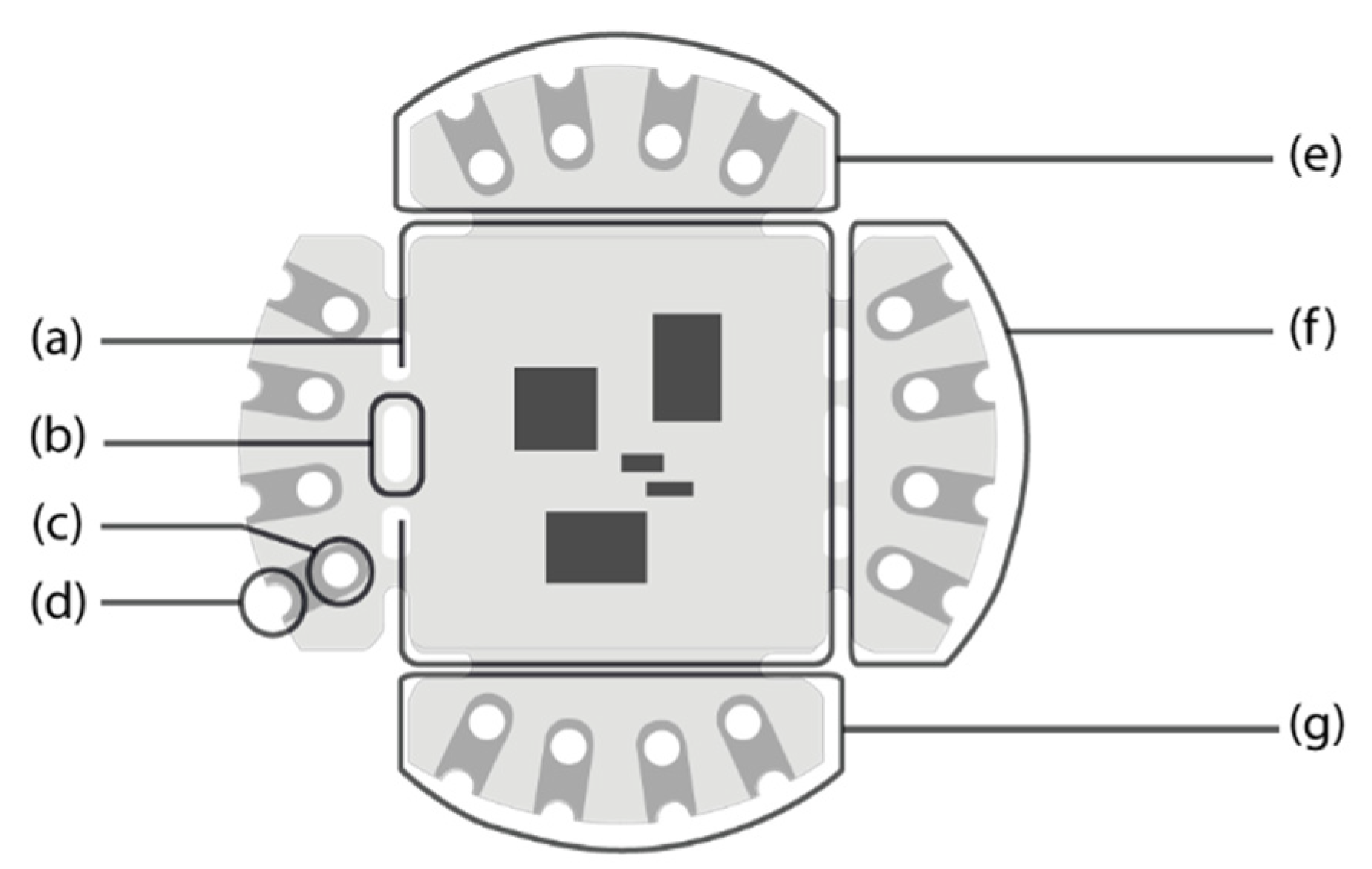
Geometrical parameters such as the position of the vias or their width to support standardized needle sizes have been defined. The design of the modules allows for the use of (industrial) embroidery machines for attachment. For manual attachment, each of the outer contact pads has a full via as well as a half-hole via (see
Figure 1c,d), to allow conductive yarn to be firmly fixed to each pad, without the risk of yarn slippage. The vias have a diameter of 1.6 mm and are thus also suitable for industrial embroidery machine needles with typical diameters of up to 1.1 mm. For additional stability, the structure connecting the outer parts to the main pad enables the modules to be fixed to the textile using non-conductive yarns (
Figure 1b). The connection pads for the communication bus are located on two opposite sides of each module (
Figure 1f,g) and are internally connected in parallel.
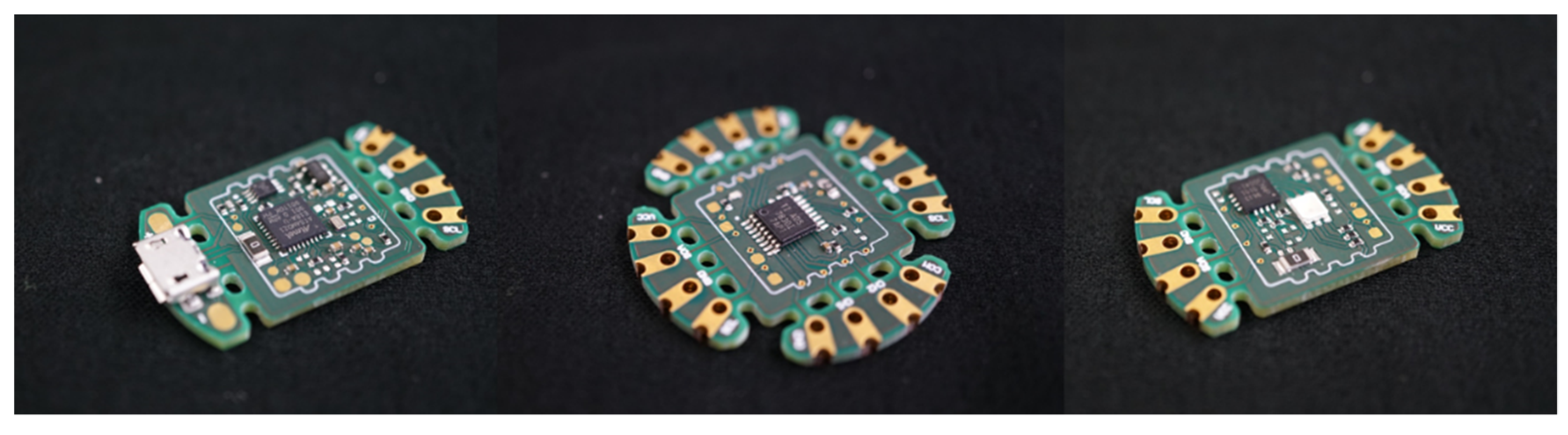
Figure 2 shows the final layout of the modules.
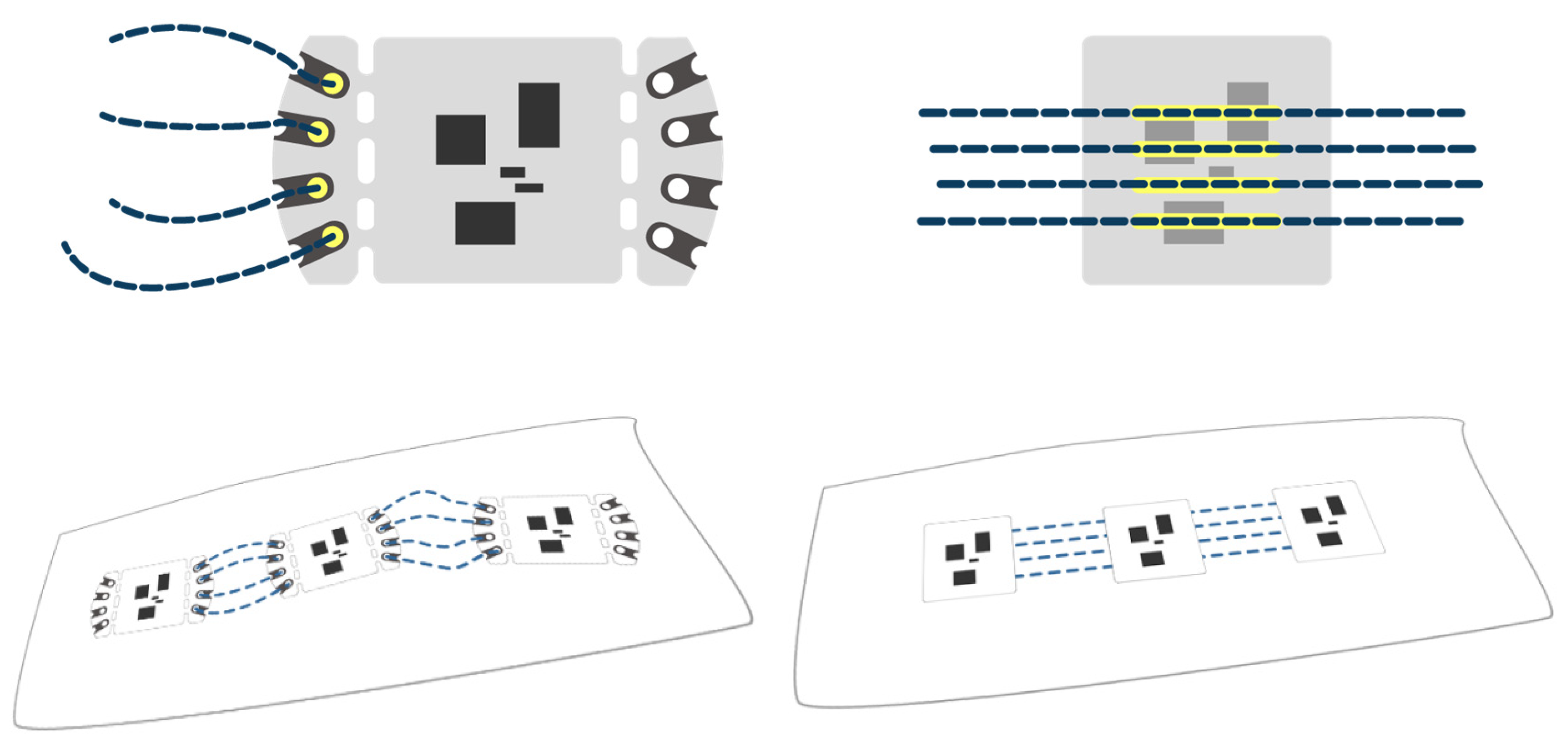
A major issue most designers pointed out is the difficulty to produce a reliable connection between the electronics and the textile during this prototyping phase. Therefore, we have developed a second method of integration to take prototypes to the next level. Besides the outer vias for manual attachment, we added additional connection pads to the bottom side of each module so they can be connected to textile-integrated circuits with the adhesive bonding technology [
6] (
Section 3). When using this method, the modules can be miniaturized to a size of 18 mm × 18 mm by removing the outer connection structures, as they are not required for bonding.
Figure 3 illustrates both connection methods.
3. E-Textile Bonder
The non-conductive adhesive bonding technology, developed at the Fraunhofer IZM [
6], has been improved and enhanced since its inception. A major advantage of this technology is the ability to reliably interconnect textile substrates and electronic modules mechanically and electrically in one single step. Established contacting methods for E-textiles such as snap fasteners, conductive adhesives, crimping, ultrasonic welding, soldering or sewing often face issues such as decreased conductivity, low dynamic reliability due to mechanical stresses, as well as no or insufficient washability [
7,
8]. The bonded contacts exhibit very good reliability results under cyclic temperature or humidity stress [
6]. First washing results show great promise for the washability as well, with little to no change in contact resistance after five wash cycles. More thorough investigations into the washability are being conducted at the moment.
A main challenge for the bonding process is the fundamental difference between textiles and electronics. Production facilities as well as the products themselves differ in many ways. Textiles are dimensionally unstable, often stretchable and limp, making overall handling and alignment challenging. Most textiles tend to degrade or melt above 200 °C—a criterion for exclusion to use contacting techniques such as soldering, a method commonly used in electronics manufacturing. Reflow soldering processes mostly require temperatures above 250 °C. In addition, electronics are mostly rigid and dimensionally stable and possess quite different mechanical properties compared to textiles. This difference in stiffness makes it impossible to apply conventional optical alignment methods that are normally used for automated assembly of electronic components. Moreover, breaks and damages can occur at the transitions between the hard electronics and soft textile components of an E-textile.
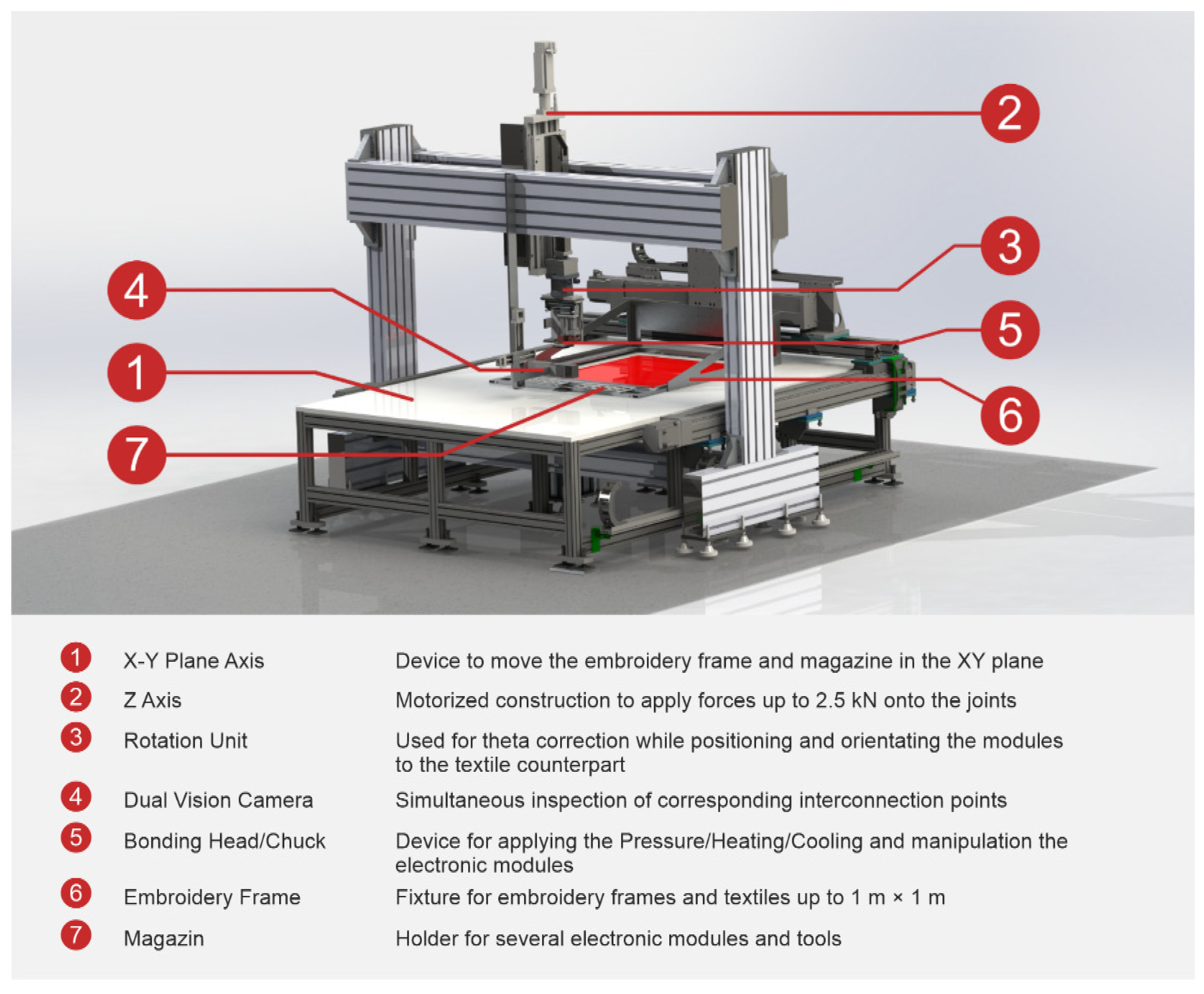
To date, no machinery exists to manufacture E-textiles on a larger scale while solving the above-mentioned problems. To overcome this challenge, we have developed a machine capable of connecting modules to a textile with integrated conductors mechanically and electrically at the same time, even for textiles with insulated wires. This machine is called the E-Textile Bonder (
Figure 4). It was developed to bring the non-conductive adhesive bond up to an industrial standard and to typical textile sizes. Additionally, it is designed for a wider use case, and we are able to investigate alternative process parameters, new materials and other contacting technologies such as sintering on a large operation area.
The Bonding Process
Initially, the textile with integrated circuits is fixed into an industrial embroidery frame and attached to the corresponding mount on the machine. The bonder can accommodate large textiles that can be processed in an area up to 1 m × 1 m. The embroidery frame can be moved in the x–y plane—analogous to industrial embroidery machines—below the bonding head. The bonding head can move in z-direction orthogonal to the x–y plane to apply pressure, and it can be rotated for theta correction.
An electronic module—e.g., a TPL module—is filled into a magazine. Modules can measure up to 50 mm × 50 mm. The accuracy to pick and place such electronic modules is tested down to match a pitch of 1.27 mm. Our TPL modules feature a pitch of 2.54 mm. The module in the magazine is subsequently picked up with the head. A dual vision camera, placed between the textile and the electronic module, allows for a simultaneous inspection of the matching contact points. We are able to merge both the image of the textile substrate with the integrated circuits and the image of the contact pads on the bottom side of the module into one combined, overlaid image. The textile can then be manually shifted until the positions of the integrated circuits align with the contact points of the module in a process called active alignment.
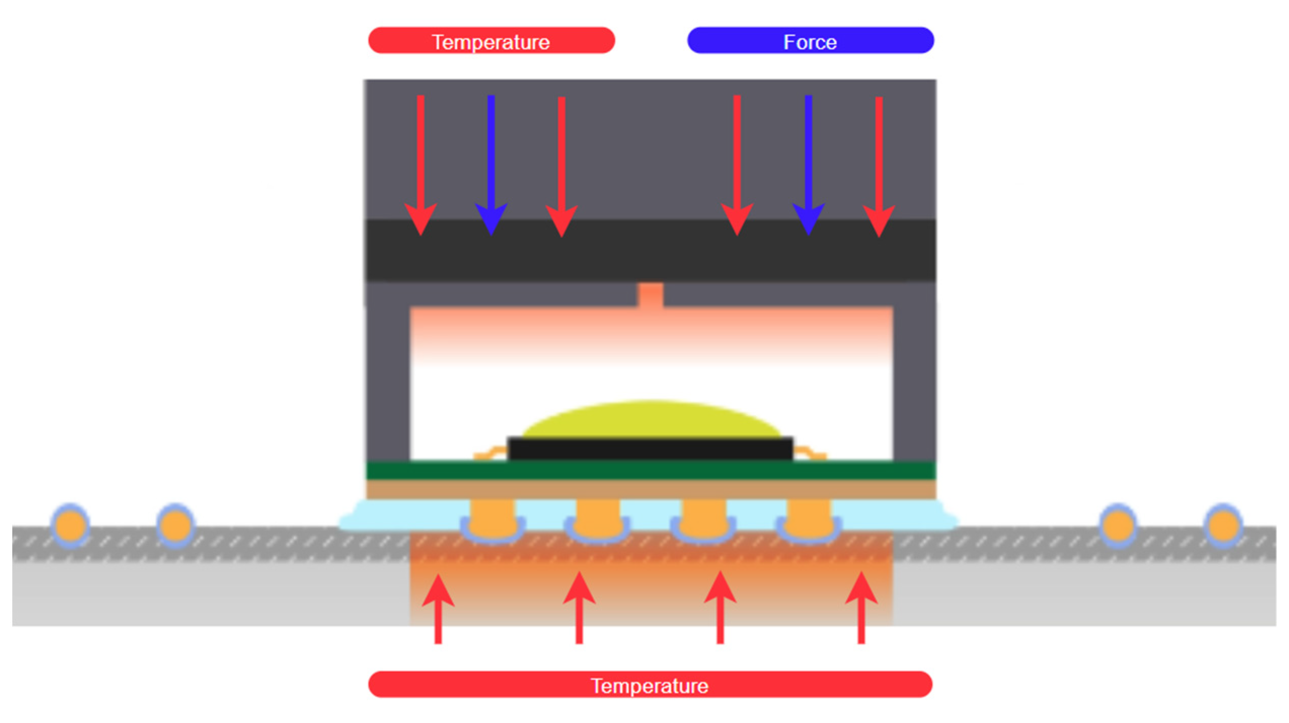
After positioning and orientation, the module is pressed against the textile with a defined amount of force while being heated via either the head or chuck or both individually, as illustrated in
Figure 5. During the process, the non-conductive adhesive and the optional wire-insulation melt and are squeezed away from the contact points. After cooling, the adhesive hardens and the modules are joined mechanically and electrically in one step. In contrast to the Flip–Chip soldering process, adding an underfill is not necessary, since the adhesives already involved in the process also take over this function. With the bonding technology, a wide range of textile-integrated circuits can be contacted: embroidered, woven, knitted or textile-based circuits, even with (thermoplastic) insulation [
6,
9].
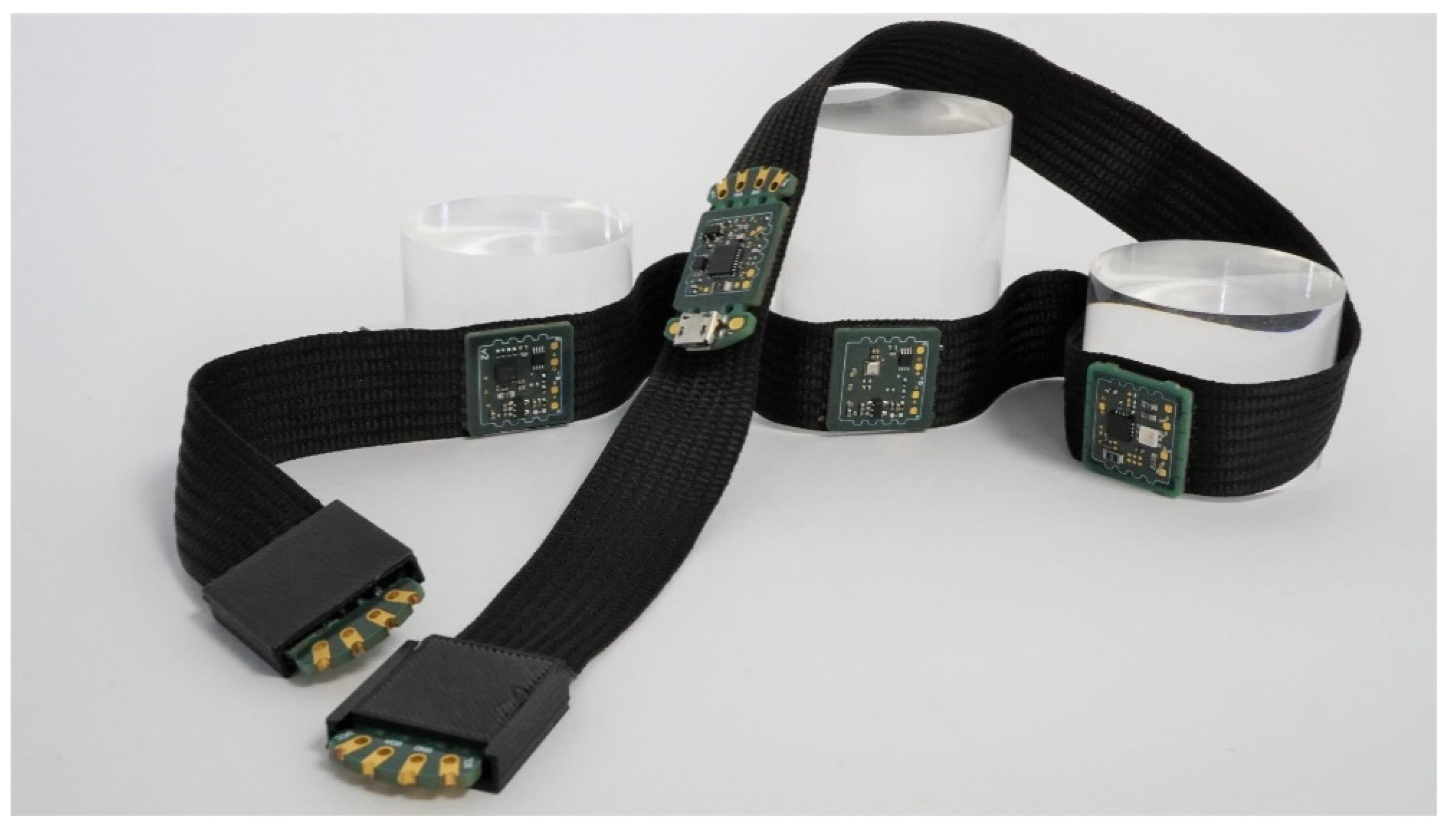
Figure 6 shows an example outcome of this process, where different TPL modules—including the main control unit—have been bonded to a ribbon belt.
4. Conclusions
The TPL toolkit offers designers the ability to focus mainly on the concepts for new E-textile developments with less attention on the implementation. It is easily usable, provides an advanced error messaging system to find broken connections and can be transferred to a more reliable industrial stage by using the textile bonding technology. No redesign of software or hardware is needed as the modules can be simply miniaturized and reused for the bonding.
The E-Textile Bonder as well as the powerful PC-based controlling software are optimized for the toolkit. The bonder is able to process a reliable joint after entering the necessary process parameters such as temperature and force. However, the active alignment of the contact pads is so far achieved only manually through visual check by an operator and is the most time-consuming part of the process. In addition to ongoing optimizations of the machine, we are also testing new materials, parameters and structures, we are thus working on an image-based automation to transfer the machine into a fully automated standard. Therefore, we utilize machine vision with the goal to develop a fully automated assembly process.
Author Contributions
TPL project coordination, idea and concept for modular toolkit: M.v.K; Hardware design TPL toolkit: K.G., Bonding technology: M.v.K. & L.S.; E-Textile-Bonder: L.S.; TPL Software and image recognition software E-Textile Bonder: M.S.; Reliability testing & textile circuit integration: S.R. All authors have read and agreed to the published version of the manuscript.
Funding
This research was partly funded by the European Union’s Horizon 2020 research and innovation program under grant agreement no. 825647 and by the German Ministry of Education and Research (BMBF) within the framework of “Zwanzig20—Partnerschaft für Innovation” as a part of the project futureTEX.
Institutional Review Board Statement
Not applicable.
Informed Consent Statement
Not applicable.
Data Availability Statement
Data sharing not applicable.
Conflicts of Interest
The authors declare no conflict of interest.
References
- Berzina, Z.; Glomb, E.; Rodriguez, S.; Große, A.; Krshiwoblozki, M.; Wolf, H.; Heltzel, D. Textile Prototyping Lab: A Platform and Open Laboratory for the Promotion of Open Innovation and Networking between Research, Design and Industry. Textile Intersections, Loughborough University, Conference Contribution. 2019. Available online: https://repository.lboro.ac.uk/articles/conference_contribution/Textile_Prototyping_Lab_-_A_Platform_and_Open_Laboratory_for_the_Promotion_of_Open_Innovation_and_Networking_between_Research_Design_and_Industry/9724700 (accessed on 4 November 2020). [CrossRef]
- Stern, B.; Cooper, T. Getting Started with Adafruit FLORA: Making Wearables with an Arduino-compatible Electronics Platform; Maker Media: San Francisco, CA, USA, 2015; ISBN 13. [Google Scholar]
- UM10204. I²C-Bus Specification. NPX. 4 April 2016. Available online: http://www.nxp.com/docs/en/user-guide/UM10204.pdf (accessed on 5 November 2020).
- Arduino IDE. Available online: http://www.arduino.cc (accessed on 6 November 2020).
- Website Textile Prototyping Lab. Available online: https://www.textileprototypinglab.com/ (accessed on 4 November 2020).
- Von Krshiwoblozki, M.; Linz, T.; Neudeck, A.; Kallmayer, C. Electronics in Textiles—Adhesive Bonding Technology for Reliably Embedding Electronic Modules into Textile Circuits. Adv. Sci. Technol. 2013, 85, 1–10. [Google Scholar] [CrossRef]
- Linz, T. Analysis of Failure Mechanisms of Machine Embroidered Electrical Contacts and Solutions for Improved Reliability. Ph.D. Thesis, Universiteit Gent, Ghent, Belgium, 2012. [Google Scholar]
- Rotzler, S.; Kallmayer, C.; Dils, C.; von Krshiwoblozki, M.; Bauer, U.; Schneider-Ramelow, M. Improving the washability of smart textiles: Influence of different washing conditions on textile integrated conductor tracks. J. Text. Inst. 2020. [Google Scholar] [CrossRef]
- Dils, C.; Werft, L.; Walter, H.; Zwanzig, M.; von Krshiwoblozki, M.; Schneider-Ramelow, M. Investigation of the Mechanical and Electrical Properties of Elastic Textile/Polymer Composites for Stretchable Electronics at Quasi-Static or Cyclic Mechanical Loads. Materials 2019, 12, 3599. [Google Scholar] [CrossRef] [PubMed]
| Publisher’s Note: MDPI stays neutral with regard to jurisdictional claims in published maps and institutional affiliations. |
© 2021 by the authors. Licensee MDPI, Basel, Switzerland. This article is an open access article distributed under the terms and conditions of the Creative Commons Attribution (CC BY) license (https://creativecommons.org/licenses/by/4.0/).

 ,
, 
