Proceeding Paper

Simulation of 2-Coil and 4-Coil Magnetic Resonance Wearable WPT Systems †

Smart Electronic Materials & System Research Group, Electronics and Computer Science, University of Southampton, Southampton SO17 1BJ, UK
*
Author to whom correspondence should be addressed.
Presented at the International Conference on the Challenges, Opportunities, Innovations and Applications in Electronic Textiles (E-Textiles 2020), Virtual venue, UK, 4 November 2020.
Proceedings 2021, 68(1), 13; https://doi.org/10.3390/proceedings2021068013
Published: 19 January 2021

Abstract

:
This paper presents the COMSOL simulations of magnetically coupled resonant wireless power transfer (WPT), using simplified coil models for embroidered planar two-coil and four-coil systems. The power transmission of both systems is studied and compared by varying the separation, rotation angle and misalignment distance at resonance (5 MHz). The frequency splitting occurs at short separations from both the two-coil and four-coil systems, resulting in lower power transmission. Therefore, the systems are driven from 4 MHz to 6 MHz to analyze the impact of frequency splitting at close separations. The results show that both systems had a peak efficiency over 90% after tuning to the proper frequency to overcome the frequency splitting phenomenon at close separations below 10 cm. The four-coil design achieved higher power efficiency at separations over 10 cm. The power efficiency of both systems decreased linearly when the axial misalignment was over 4 cm or the misalignment angle between receiver and transmitter was over 45 degrees.

1. Introduction

Magnetically coupled resonant wireless power transfer (MR-WPT) can efficiently supply e-textiles by using different configurations. Typical MR-WPT systems use two-coil or four-coil structures. The four-coil design differs from the common two-coil design with the addition of a driving coil and a load coil placed alongside the original two coils. Figure 1 shows the models of the two-coil and two-coil MR-WPT systems.
The textile coils can be fabricated by an embroidery machine to build the wearable MR-WPT systems. This paper presents the simulations of embroidered planar two-coil and four-coil structured MR-WPT systems fabricated using copper litz wire.

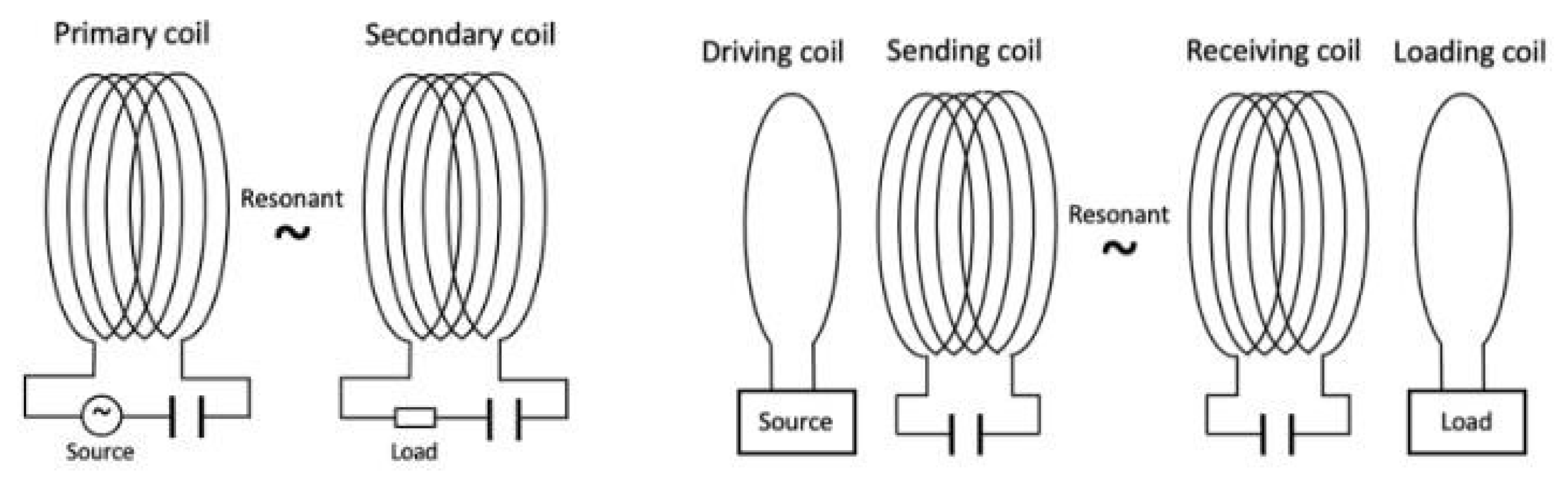
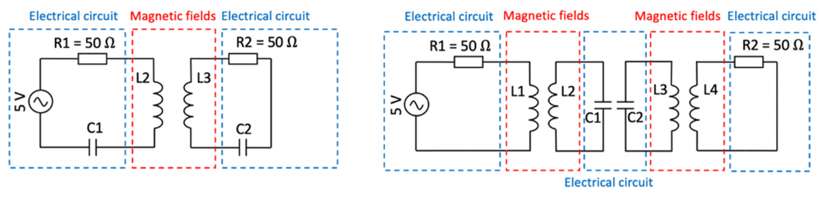
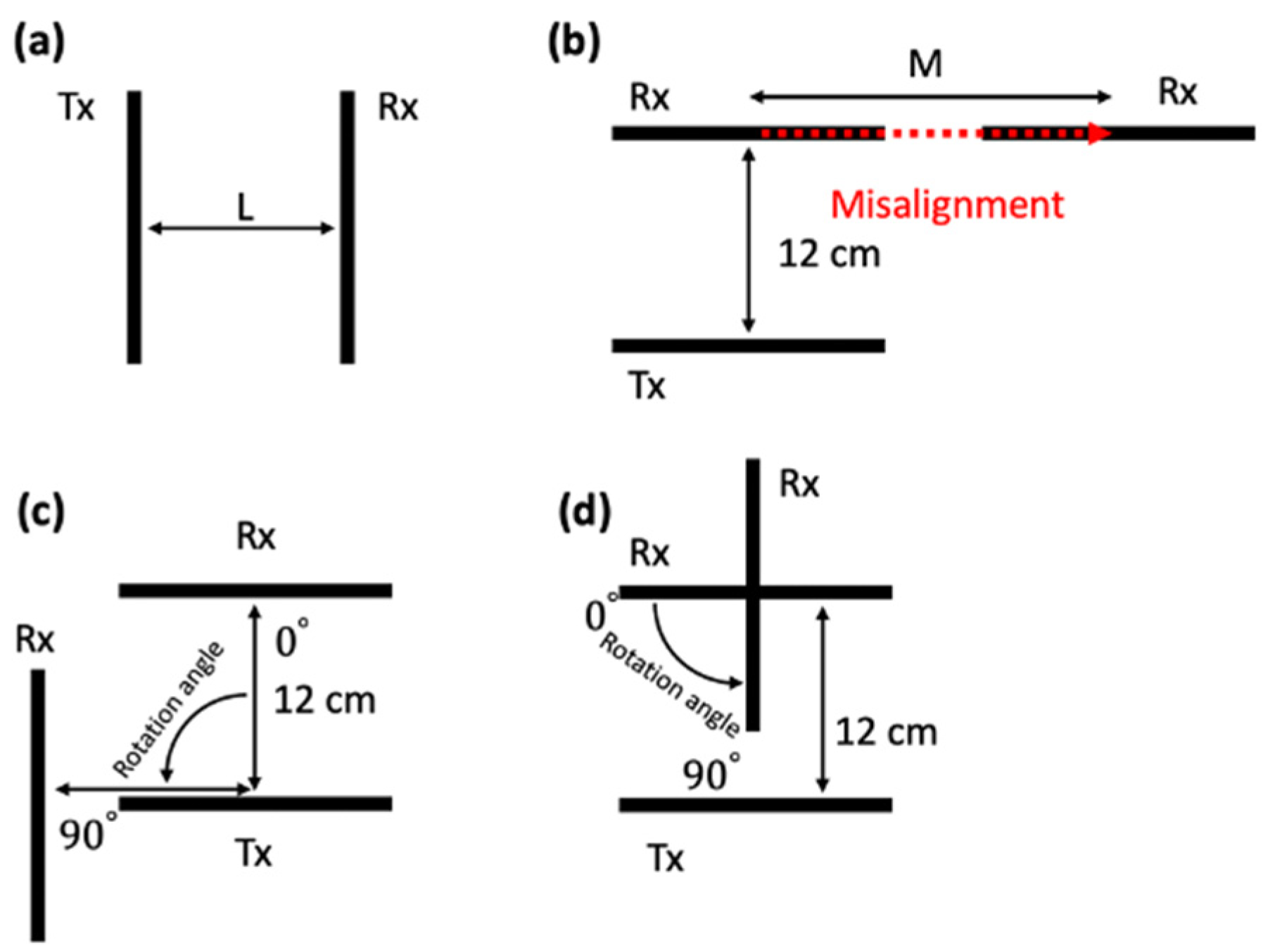
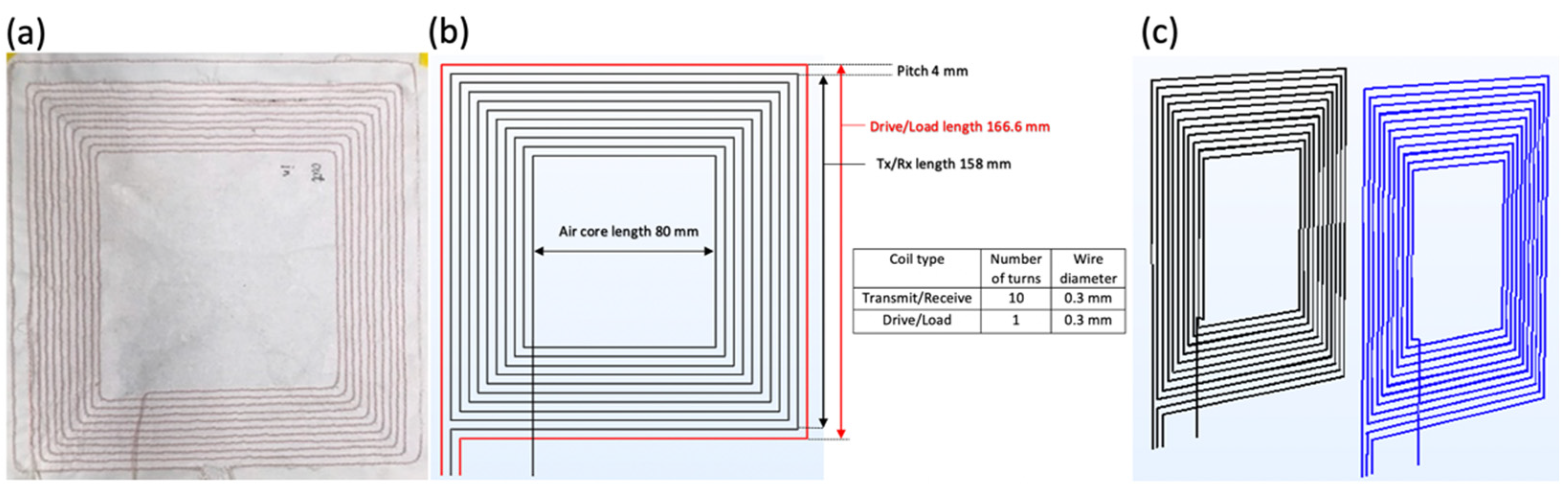
2. Materials and Methods

Figure 2 shows the schematics of the two-coil and four-coil systems simulated within the COMSOL package. The coil models (noted in the red region in Figure 2) were drawn and simulated in the frequency domain using magnetic field physics. The electrical components interfaced with the coils (noted in the blue region in Figure 2) were set up using electrical circuit physics.
The transmitting coil L2 and receiving coil L3 were designed to be identical for both systems, resulting in the same values for lumped capacitors C1 and C2. The driving coil L1 and load coil L4 in the four-coil structure were identical to each other. Therefore, the receiver Rx (consisting of only the receiving coil for the two-coil system or both the receiving and load coils for the four-coil system) was identical to the transmitter Tx (consisting of only the transmitting coil for the two-coil system or both the driving and transmitting coils for the four-coil system).
The coils were simulated by 0.3 mm thick solid copper wire, modeling the embroidered litz wire coils. Figure 3a shows the photograph of the textile coils sewn on the surface of the textile. The silk-coated copper litz wires consisted of 36 individual strands of 40 µm copper wires having an overall diameter of 0.3 mm. The geometry and layout of the coils forming the transmitter (Tx) are shown in Figure 3b. The black coil represents the transmitting coil L2, and the red loop placed outside L2 with a 4 mm pitch represents the driving coil L1, which is only used in the four-coil system. Figure 3c shows that the transmitter Tx and receiver Rx of the four-coil system were separated by a given distance, which would be varied in the simulated magnetic field analysis.
Figure 4 shows the top view of the transmitter and receiver for four dependent studies. The transfer distance is defined as the coil separation L in Figure 4a and varied from 0 to 20 cm. The misalignment distance L in Figure 4b varied from 0 to 14 cm. The rotation angle varied from 0 to 90 degrees for the two rotating cases shown in Figure 4c,d.

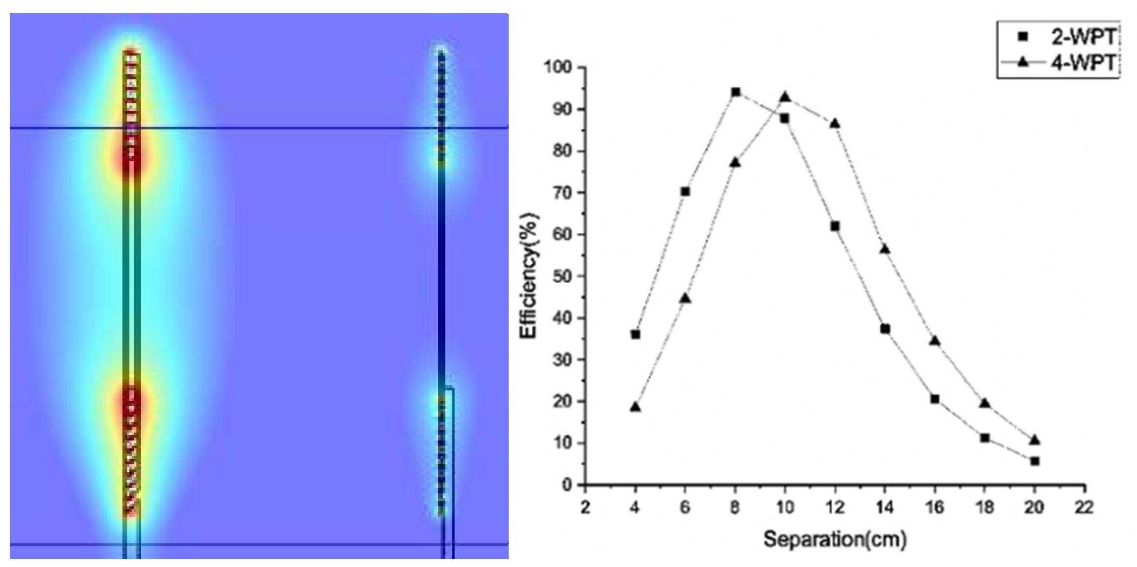
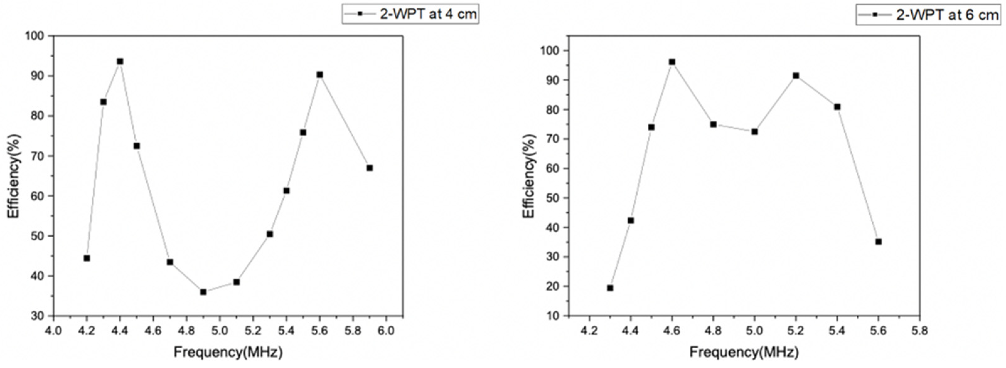
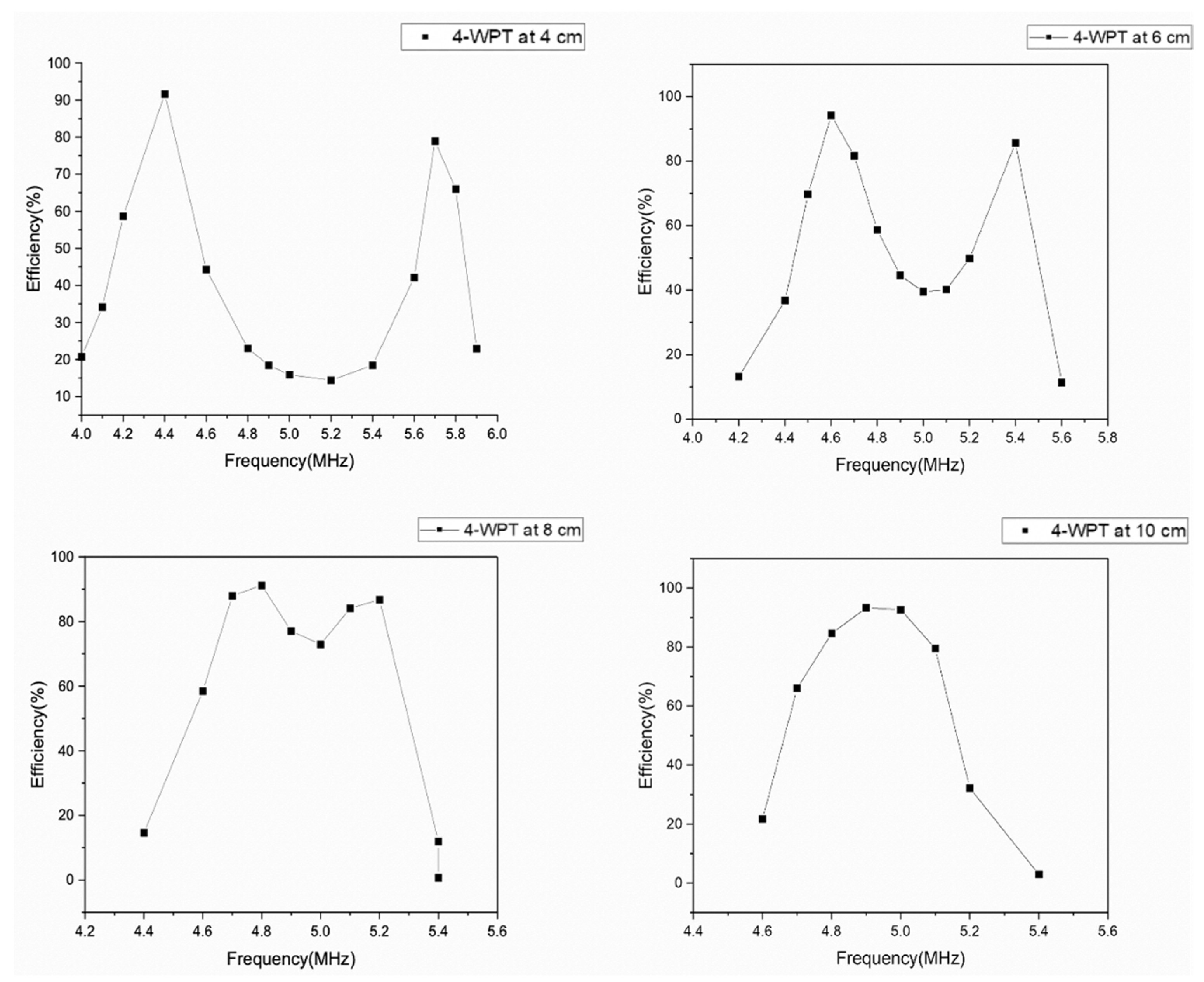
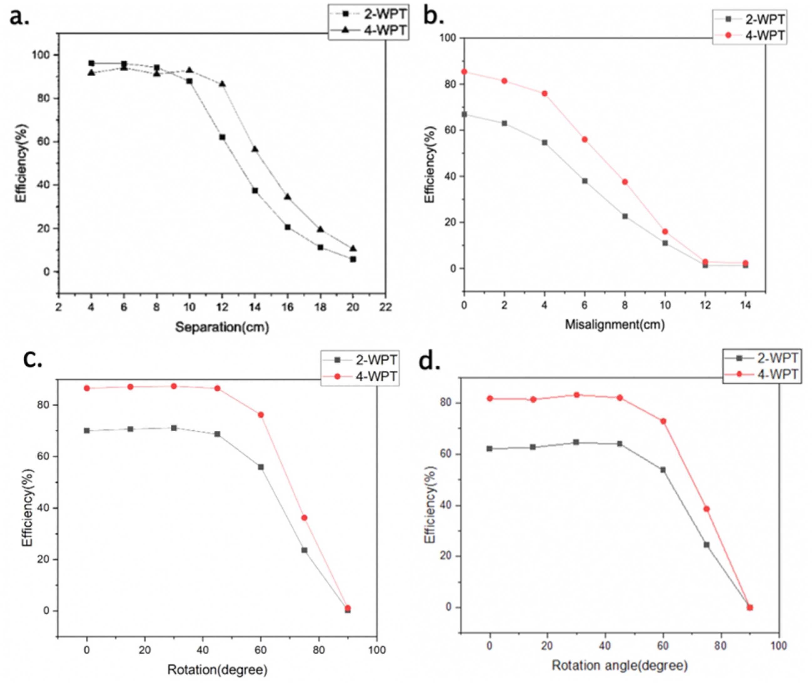
3. Results and Discussion

The wireless power transfer efficiency can be derived from [1,2] as η w p t = | S 21 | 2 = 4   R S R L ( V L V S ) 2 .
The simulated magnetic fields are shown in Figure 5. The results of the coil separation study are shown as plots of the power transfer efficiency against the separation distance in Figure 5, where the efficiency had peak values over 90% at 8 cm of separation for the two-coil system and 10 cm of separation for the four-coil system.
At short transfer distances for both systems, the frequency splitting phenomenon occurred where the peak power efficiency was no longer present at the resonant frequency. The peak values of the transfer efficiency occurred at below and above the original resonance frequency. The efficiency performances of the two-coil and four-coil systems were analyzed in a frequency domain where the driving frequency was varied. The two-coil system was driven from 4 MHz to 6 MHz at 4 cm and 6 cm of coil separation, respectively. The power transfer efficiency was plotted as a function of the operating frequency shown in Figure 6. It was observed that the peak efficiency occurred at 4.4 MHz and 5.6 MHz for 4 cm of separation. As the separation was increased to 6 cm, the splitting range narrowed. The peak efficiency first occurred at 4.6 MHz and then 5.2 MHz.
The four-coil system had a longer frequency-splitting range of 10 cm than the two-coil system (8 cm). From Figure 7, the two frequencies possessing the peak power efficiencies tended to unify when the coil separation was increased from 4 cm to 10 cm.
To overcome the impact of frequency splitting, both the two-coil and four-coil systems were tuned to the peak power frequency at short separation distances below 10cm. The new results are plotted in Figure 8a. The two-coil design remained at a higher efficiency than the four-coil design when the separation distance was below 10 cm. The efficiency started to decrease rapidly from 87% for the two-coil system and 92% for the four-coil system when the distance reached 10 cm. There was very little power delivered to the load when the transfer distance was over 20 cm.
The power efficiency performances of axial misalignments from 4 cm to 14 cm at 12 cm of coil separation are plotted and shown in Figure 8b. A linear drop was observed at a 4 cm misalignment distance for both systems. For the angular misalignment, Figure 8c,d shows that the efficiency remained stable up to a 45 degree angle of the receiver coil with respect to the transmitter, after which it decreased linearly.

4. Conclusions

This paper presented simulations of two-coil and four-coil structured systems using simplified coil models in the COMSOL package. After tuning to a frequency that overcame the frequency splitting phenomenon at a close transfer distance, both systems had peak efficiencies over 90%. The four-coil design achieved better performance when the distance was increased over 10 cm. The transfer distance with a maintained power efficiency over 90% was around 12 cm for the four-coil system and 10 cm for the two-coil system. The power efficiency decreased linearly when the axial misalignment separation was over 4 cm and the misalignment angle between the receiver and transmitter was over 45 degrees.

Informed Consent Statement

Not applicable.

Data Availability Statement

All data supporting this study are openly available from the University of Southampton repository at https://doi.org/10.5258/SOTON/D1716.

References

  1. Kang, S.H.; Nguyen, V.T.; Jung, C.W. Analysis of MR-WPT using planar textile resonators for wearable applications. IET Microw. Antennas Propag. 2016, 10, 1541–1546. [Google Scholar] [CrossRef]
  2. Sample, A.P.; Meyer, D.A.; Smith, J.R. Analysis, experimental results, and range adaptation of magnetically coupled resonators for wireless power transfer. IEEE Trans. Ind. Electron. 2011, 58, 544–554. [Google Scholar] [CrossRef]
Figure 1. Typical models of two-coil (left) and four-coil (right) magnetically coupled resonant wireless power transfer (MR-WPT) systems.
Proceedings 68 00013 g001
Figure 2. The schematics of two-coil (left) and four-coil (right) MR-WPT systems in COMSOL.
Proceedings 68 00013 g002
Figure 3. (a) Photograph of embroidered textile coils. (b) Geometry and layout of coil models for Tx and Rx. (c) Tx and Rx of the four-coil system spaced at a certain distance.
Proceedings 68 00013 g003
Figure 4. Top view of Tx and Rx in study of (a) the coil separation, (b) axial misalignment, (c) receiver rotating around the transmitter and (d) the self-spinning of the receiver.
Proceedings 68 00013 g004
Figure 5. Simulated coils in the magnetic field (left) and the coil separation study at a resonance of 5 MHz (right).
Proceedings 68 00013 g005
Figure 6. Transfer efficiency of the two-coil system analyzed in a frequency domain at a separation of 4 cm (left) and 6 cm (right).
Proceedings 68 00013 g006
Figure 7. The MR-WPT efficiency of the four-coil system analyzed in frequency domain at a separation of 4 cm, 6 cm, 8 cm and 10 cm.
Proceedings 68 00013 g007
Figure 8. (a) Power efficiency against coil separation after the frequency was tuned. (b) Power efficiency at 12 cm of coil separation studied in axial misalignments. (c) Receiver rotating around the transmitter. (d) Receiver rotating around itself (self-spinning).
Proceedings 68 00013 g008
Publisher’s Note: MDPI stays neutral with regard to jurisdictional claims in published maps and institutional affiliations.

