Abstract
Various types of heart diseases, including cardiac arrhythmia, myocardial infarction, and coronary artery disease, are one of the main reasons behind the causes of death around the world. It can be mitigated if we know the pulse rate and monitor it properly. However, constant monitoring can be expensive for the private sector and so we are proposing to solve the problem by the implementation of a wireless network based on Bluetooth. The pulse rate data is sent from Arduino Uno via Bluetooth to Smartphone and it can be analyzed by the user and sent it to an expert doctor with a low cost and more efficiently. This project identifies with a heartbeat rate estimation gadget, including a heartbeat rate sensor unit that distinguishes a client’s heartbeat rate, a sign preparing unit that receives and measures the sign produced from the sensor, and a remote sign sending unit that takes the sign from the handling unit and then communicates the sign to the arranged gadget. The sensor unit distinguishes the recurrence of the progress of blood thickness to get the pulse, carefully and productively finding the location of the pulse, participating in the method of remote transmission and accordingly, our motivation of advancing precision of identification and improving comfort of utilizing is accomplished. The model incorporates Arduino Uno, Pulse Rate Sensor, Bluetooth Board, Breadboard, USB link, and so forth.We communicate the information utilizing Bluetooth to Smartphone utilizing Pulse Rate Monitor circuit furnished with Arduino Uno.
Keywords:
wireless monitoring; Pulse Rate; Arduino Uno; Smartphone; sensor units; heart diseases; Bluetooth; Breadboard; medical 1. Introduction
These days, the number of individuals affected by experiencing cardiovascular sicknesses is increasing step by step. Thus, the desire emerges to plan a viable framework that would give us exact and speedy heartbeat rate readings [1,2,3]. The readings are communicated to the associated cell phone through Bluetooth, for example through remote media. By giving admittance to a cell phone and heartbeat rate circuit, we eliminate the obstructions of specialists and patients, offer clinical types of assistance, and outfit the patient with such innovation that they can get their heartbeat rate information with a cell phone and send the information to an expert specialist or paramedic who can give them different tips what to do during arrhythmias or other cardiovascular issues, or provide crisis mediation to paramedics, in such circumstances as in myocardial localized necrosis [4]. In-home wellbeing, the utilization of innovation that permits patients to screen their fundamental signs from their home and impart results to a medical clinic proficient remotely could build the capacity to address an issue before a patient requires intense consideration. The heartbeat is the rate of somebody’s pulse. Heartbeat rate is normally called your pulse, which is measured by how many times the heart beats per minute (bpm). In any case, the beat and quality of the heartbeat can likewise be noted, just as whether the vein feels hard or delicate. Changes in somebody’s pulse or mood, a frail heartbeat, or a hard vein, might be brought about by coronary illness or another issue. As the heart siphons blood through your body, you can feel a beating in a portion of the veins near the skin’s surface, for example, in your wrist, neck, or upper arm. Counting the beat rate is a straightforward method to discover how quickly your heart is pulsating [4].
2. System Design
This research identifies with a heartbeat rate estimation gadget, containing a heartbeat rate sensor unit that distinguishes a client’s heartbeat rate, a sign preparing unit that receives and measures the sign created from the sensor, and a remote sign sending unit that takes the sign from the handling unit and then communicates the sign to the designed gadget. The sensor unit unequivocally recognizes the recurrence of progress of blood thickness in order to get the pulse, carefully and productively discovering the pulse, participating in the method of remote transmission, and subsequently, our motivation of advancing exactness of location and improving the comfort of utilizing is accomplished. Figure 1 shows the flow diagram of the system. The model incorporates Arduino Uno, Pulse Rate Sensor, Bluetooth Board, Breadboard, USB link, and so forth.We communicate our information through Bluetooth to cell phones utilizing Pulse Rate Monitor circuit furnished with Arduino Uno.

Figure 1.
Flow-diagram of the system.
Hardware and Software
This system has been created by using Arduino Uno, Pulse Sensor, Bluetooth HC-05 class, Breadboard, and jumper wires.
The heartbeat sensor depends on the rule of photoplethysmography [5,6,7,8,9]. It quantifies the adjustment in volume of blood through any organ of the body, which causes an adjustment in the light force through that organ (a vascular area). On account of uses where the heartbeat rate is to be observed, the circumstance of the beats is more significant. The progression of blood volume is determined by the pace of heartbeats and since light is taken up by the blood, the sign heartbeats are equal to the heartbeat beats. There are two sorts of photoplethysmography.
- Transmission: Light discharged from the light-producing gadget is sent through any vascular area of the body like the ear cartilage and received by the locator.
- Reflection: Light produced from the light-radiating gadget is reflected by the locales.
We have utilized two heartbeat rate sensors; one is a modest Chinese variation and another is a unique heartbeat rate sensor from SparkFun (USA). Figure 2 presents the pulse sensor. The two sensors worked productively. The information we got from the US variant is steadier and more dependable.
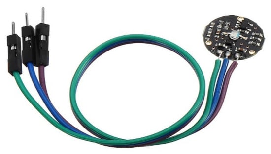
Figure 2.
Pulse Sensor [10].
The fundamental heartbeat sensor comprises of a light-emanating diode and an indicator like a light recognizing resistor or a photodiode. The heartbeat beats make a variety in the progression of blood in various areas of the body. At the point when a tissue is lit up with the light source, for example, light discharged by the drove, it either mirrors (a finger tissue) or communicates the light (ear cartilage). A portion of the light is taken upby the blood and the sent or the mirrored light is receivedby the light indicator. The measure of light retained relies upon the blood volume in that tissue.
The indicator yield is in the type of electrical sign and is relative to the heartbeat rate. This sign is a Direct Current (DC) signal identifying the tissues and the blood volume and the Alternating Current AC part simultaneously with the heartbeat and is brought about by pulsatile changes in the blood vessels’ blood volume is superimposed on the DC signal. Subsequently, the significant necessity is to detach that AC part for what it is worth of prime significance. To accomplish the undertaking of getting the AC signal, the yield from the identifier is first sifted utilizing a 2-phase High Pressure -Low Pressure HP-LP circuit and is then changed over to advanced heartbeats utilizing a comparator circuit or utilizing basic Analog to Digital Converter ADC. The advanced heartbeats are given to a microcontroller for ascertaining the heartbeat rate, given by the recipe Beats Per Minute (BPM) = 60*f; where f is the beat recurrence.
An Arduino UNO is presented in Figure 3. Arduino/Genuino [11] Uno is a microcontroller board dependent on the ATmega328P. It has 14 advanced info/yield pins (of which 6 can be utilized asPulse Width Modulation PWM yields), 6 simple information sources, a 16 MHz quartz precious stone, a USB association, a force jack, an ICSP header, and a reset button. It contains an architect expected to help the microcontroller just by interfacing it to a PC with a USB link or force it with an AC-to-DC connector or battery to start. The Uno is different from all former sheets in that it does not utilize the FTDI USB-to-chronic driver chip. All things considered, it includes an ATmega16U2 customized as a USB-to-chronic converter. This helper microcontroller has its USB boot loader, which permits progressed clients to reconstruct it.
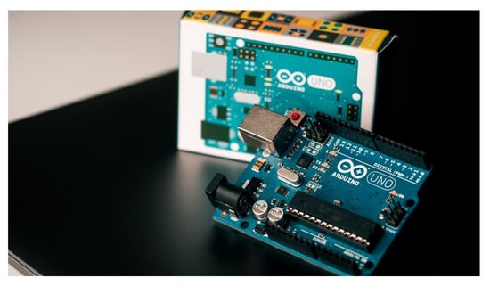
Figure 3.
Arduino Uno [12].
Bluetooth module is shown in Figure 4. HC-05 module is a simple to utilize Bluetooth Serial Port Protocol (SPP) module, intended for straightforward remote sequential association arrangement. The HC-05 Bluetooth Module can be utilized in a Master or Slave arrangement, making it an incredible answer for remote correspondence. This sequential port Bluetooth module is a completely qualified Bluetooth V2.0+EDR (Enhanced Data Rate) 3Mbps Modulation with a complete 2.4GHz radio handset and baseband. It utilizes CSR Bluecore 04-External single-chip Bluetooth framework with CMOS innovation and with Adaptive Frequency Hopping Feature (AFH).
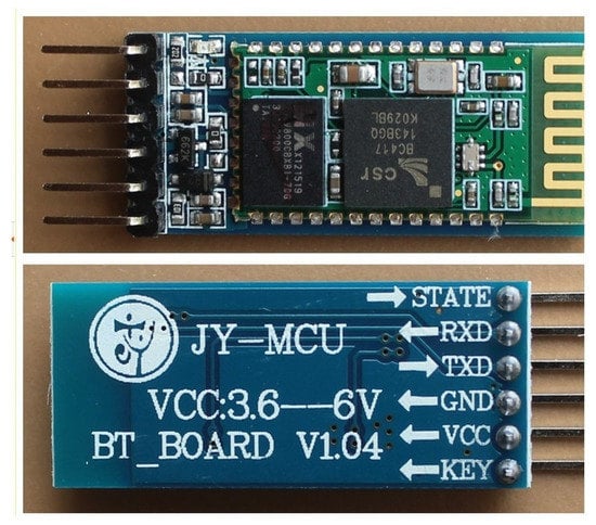
Figure 4.
Bluetooth module [13].
3. Result Analysis
We utilized an open-source programming language/advancement instrument for composing programs on different PCs, which was valuable when we need the PCs to converse with Arduino. The android application is local and we utilized java and XML for this. We utilized Bluetooth to get the information from the gadget and afterward we utilized this information to draw the chart. It would take the perusing from the Arduino and show it on NSU_PRM that we explicitly produced for that reason. A screen capture of the android application interface is given below in Figure 5.
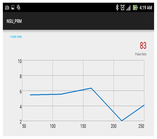
Figure 5.
Android application interface.
This paper identifies with a heartbeat rate estimation gadget, involving a heartbeat rate sensor unit that distinguishes a client’s heartbeat rate, a sign preparing unit that receives and measures the sign created from the sensor, and a remote sign communicating unit that takes the sign from the handling unit and then send the sign to the arranged gadget. The sensor unit accurately distinguishes the recurrence of progress of blood thickness in order to get the pulse, thoroughly and productively discovering the pulse along with the procedure of remote transmission, and in this way, our motivation of advancing precision of location and improving accommodation of utilizing is accomplished. The model consists of Arduino Uno, Pulse Rate Sensor, Bluetooth Board, Breadboard, USB link, and so forth. We send our information through Bluetooth to Smartphone utilizing Pulse Rate Monitor circuit outfitted with Arduino Uno. Figure 6 shows the pulse rate result in Arduino Integrated Development Environment (IDE).
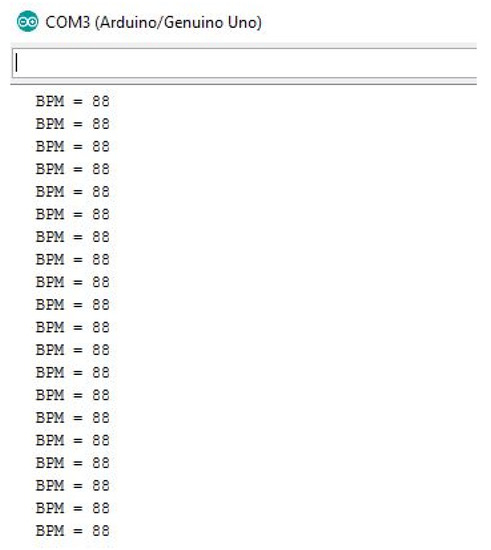
Figure 6.
Pulse rate result in Arduino Integrated Development Environment (IDE).
We have estimated the beat pace of numerous volunteers both by our gadget circuit and physically. The two outcomes nearly corresponded precisely. Figure 7 shows Arduino IDE plotter. The normal value for the heartbeat rate was around 67 to 80 BPM. What is more, we got an appropriate incentive on Arduino Uno and Android Apps. By dissecting the manual estimations of the heartbeat rate, we got a minimal blunder of +/−2%, as it were. So it agreed with our value precisely.
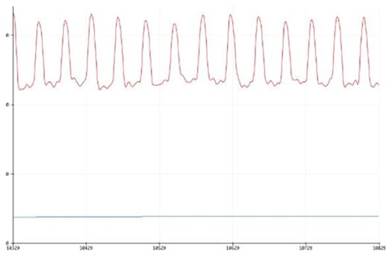
Figure 7.
Arduino IDE plotter.
4. Conclusions
It has been effectively demonstrated through the model that it works impeccably. These days, the number of individuals affected by experiencing heart infections is increasing step by step. Because of this, an inclination emerged to plan a viable framework that would give us precise and brisk heartbeat rate readings The readings are sent to the associated cell phone through Bluetooth, for example through remote media. By giving admittance to a cell phone and heartbeat rate circuit, we eliminate the hindrances of specialists and patients, offer clinical types of assistance, and furnish the patient with such innovation that they can get their heartbeat rate information with a cell phone and send the information to a pro specialist or paramedic who can give them different tips what to do during arrhythmias or other cardiovascular issues or provide crisis mediation to paramedics in such circumstances as in myocardial localized necrosis. In-home wellbeing, the utilization of innovation that permits patients to screen their imperative signs from their home and impart results to a medical clinic proficient remotely could expand the capacity to address an issue before a patient requires intense consideration. In this paper, we achieved a remote heartbeat rate screen with Arduino Uno, Bluetooth Module, and Pulse Sensor and so forth. The venture was done effectively and it shows a diagram of heartbeat rate remotely in the Android application through the Bluetooth gadget. We estimated the beat pace of numerous volunteers both by our gadget circuit and physically. The two outcomes nearly corresponded precisely. The normal value for the heartbeat rate was around 67 to 80 BPM.
Funding
This research received no external funding.
References
- Mensink, G.B.M.; Hoffmeister, H. The relationship between resting heart rate and all-cause, cardiovascular, and cancer mortality. Eur. Heart J. 1997, 18, 1404–1410. [Google Scholar] [CrossRef] [PubMed]
- Kannel, H.W.B.; Kannel, C.; Paffenbarger, R.S.; Cupples, L.A. Heart rate and cardiovascular mortality: The Framingham Study. Am. Heart J. 1987, 113, 1489–1494. [Google Scholar] [CrossRef]
- Thaulow, E.; Eriksson, J.E. How important is heart rate? J. Hypertens. 1991, 9 (Suppl. 7), S17–S23. [Google Scholar] [CrossRef] [PubMed]
- Landicho, L.C.L.; Magbalon, I.R.; Reyes, C.P.S. A wireless electrocardiography in superintending cardiac rate extremes with global positioning capability to remotely localize specimen. In Proceedings of the 2015 IEEE International Conference on Control System, Computing and Engineering (ICCSCE), Penang, Malaysia, 27–29 November 2015; pp. 141–145. [Google Scholar]
- Reyes, I.; Nazeran, H.; Franco, M.; Haltiwanger, E. Wireless photoplethysmographic device for heart rate variability signal acquisition and analysis. In Proceedings of the 2012 Annual International Conferenceof the IEEE Engineering in Medicine and Biology Society, SanDiego, CA, USA, 28 August–1 September 2012; pp. 2092–2095. [Google Scholar]
- Rotariu, C.; Manta, V. Wireless system for remote monitoring of oxygen saturation and heart rate. In Proceedings of the 2012 Federated Conference on Computer Science and Information Systems (FedCSIS), Wroclaw, Poland, 9–12 September 2012; pp. 193–196. [Google Scholar]
- Cristea, C.; Pasarica, A.; Andruseac, G.; Dionisie, B.; Rotariu, C. A wireless ECG acquisition device for remote monitoring of heart rate and arrhythmia detection. In Proceedings of the 2015 E-Health and Bioengineering Conference (EHB), Iasi, Romania, 19–21 November 2015; pp. 1–4. [Google Scholar]
- Jubadi, W.M.; Sahak, S.F. Heartbeat monitoring alert via SMS. In Proceedings of the 2009 IEEE Symposium on Industrial Electronics & Applications, Kuala Lumpur, Malaysia, 4–6 October 2009; pp. 1–5. [Google Scholar]
- Leijdekkers, V.G.P. A Health Monitoring System Using Smart Phones and Wearable Sensors. Int. J. ARM 2007, 8, 29–36. [Google Scholar]
- Pulse Sensor. Available online: https://www.banggood.com/Pulsesensor-Pulse-Heartbeat-Rate-Sensor-Module-Pulse-Sensor-p-1327349.html?akmClientCountry=BD&&cur_warehouse=CN (accessed on 5 May 2020).
- Arduino—ArduinoBoardUno, Arduino.cc. 2017. Available online: https://www.arduino.cc/en/pmwiki.php?n=Main/arduinoBoardUno (accessed on 5 May 2020).
- Arduino Uno. Available online: https://unsplash.com/s/photos/arduino-uno (accessed on 5 May 2020).
- Bluetooth Module. Available online: https://unsplash.com/s/photos/arduino-uno (accessed on 5 May 2020).
Publisher’s Note: MDPI stays neutral with regard to jurisdictional claims in published maps and institutional affiliations. |
© 2020 by the authors. Licensee MDPI, Basel, Switzerland. This article is an open access article distributed under the terms and conditions of the Creative Commons Attribution (CC BY) license (https://creativecommons.org/licenses/by/4.0/).