1. Introduction
An active magnetic bearing (AMB) is a type of electromagnetic equipment that can support a high-speed rotating rotor. Compared with traditional bearings, an AMB has many unique advantages, such as no contact, no wear, no lubrication, low power consumption and adjustable stiffness and damping [
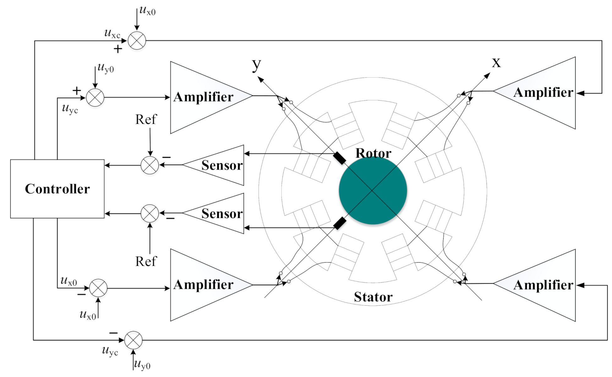
1]. AMBs have a wide application prospect in fields like uninterruptible power supply (UPS) and satellite control moment gyroscope (CMG). These devices have high requirements for the overall performance and dependability of the AMB system. An AMB is a typical open-loop unstable system, and it cannot work normally until feedback control is applied. Its basic principle is shown in
Figure 1. The displacement sensor detects the displacement of the rotor off center in two vertical directions and sends it to the controller. The controller calculates and adjusts the reference current signal with an algorithm. The power amplifier and electromagnet are the actuators of the AMB. The power amplifier amplifies the reference current signal output by the controller to excite the electromagnet to produce the desired electromagnetic force. Therefore, the performance and reliability of the power amplifier are of great significance for the stable operation of the AMB.
As an important part of the magnetic levitation actuator, the power amplifier has been studied by many scholars. The linear power amplifier is the first drive of the AMB, but the power consumption of electronic components in the linear region is very large, so the power amplifier type has been changed to a switching power amplifier (SPA) in the last 20 years. Xin Cheng et al. studied the accuracy characteristics of an SPA under two-level modulation and analyzed the main factors affecting the inherent current ripple [
2]. Yuan Ren et al. proposed a predictive current control method based on the proportional–differential current-sensing resistor networks, which solved the problem of the digital control delay of the H-bridge power amplifier, reduced the computation load of the algorithm, improved the control accuracy and reduced the current noise [
3]. To reduce the influence of phase lag of an SPA on system stability and the static and dynamic performance of an AMB, Jiancheng Fang et al. proposed an adaptive phase-lead compensation strategy based on unsymmetrical current sampling resistance networks [
4]. Dong Jiang et al. designed a reduced switch converter topology SPA, which reduced the number of switches, gate drivers and pulse width modulation (PWM) signals, and analyzed the modulation methods and the control strategy of the middle bridge arm [
5]. Furthermore, Dong Jiang et al. carried out global optimization for the whole system of multi-axis AMBs drive, and proposed a topology of shared-bridge drive with reverse direction, which was then extended to fault-tolerant drive [
6]. For the AMBs system with five degrees of freedom (DOF), Jie Zhou et al. designed an SPA with a five-phase six-leg topology, and used a one-cycle algorithm for control, which effectively reduced the current ripple [
7].
However, research on the SPA of an AMB at present mainly focuses on the control algorithm to improve the output current accuracy of the half-bridge or full-bridge topology power amplifier, and some studies focus on the topology optimization of the SPA and have put forward the corresponding control method, which significantly reduces the number of components. However, the performance evaluation of different topologies is not given, especially in different coil pair arrangements and the distributions of bias current, and needs further study.
Therefore, this paper evaluates different topologies of the SPA and discusses the SPA performance of different topologies with different coil pair arrangements and bias current distributions, which can provide theoretical guidance and reference for the design of AMB power amplifiers and is of great significance in improving the reliability of power amplifiers and the wide application of AMBs.
2. Several Topologies of SPA
At present, magnetic bearing SPAs generally adopt the bridge topology, and some other topologies are modified based on the full-bridge topology.
Figure 2 demonstrates a typical full-bridge topology circuit. The controller controls the opening and closing of four switches through the PWM signal with four isolated drive circuits, and adjusts the current in the coil in real time. In addition, the coil current can be bidirectional. If S
1, S
2, or S
3, S
4 are opened at the same time, the coil current can be increased or decreased under the DC bus voltage
Vdc and while S
1, S
3, or S
2, S
4 are opened simultaneously, the coil current freewheels. Hence, the coil current can follow the reference current signal with high performance by controlling the four switches. However, if such a topology is adopted, four power switches and four isolated drive circuits are required for the control of one coil.
In order to improve the support stiffness of the AMB, the motion of a rotor with a single DOF generally needs two coils with differential control. Therefore, two radial AMBs with two DOFs, as shown in
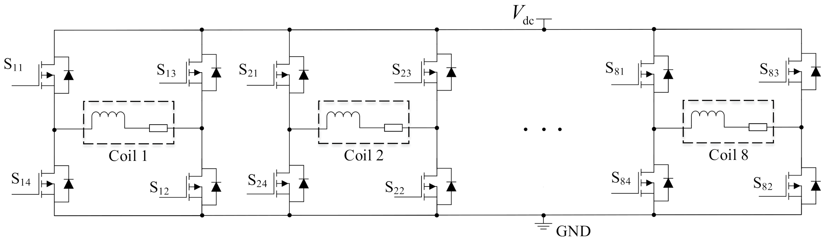
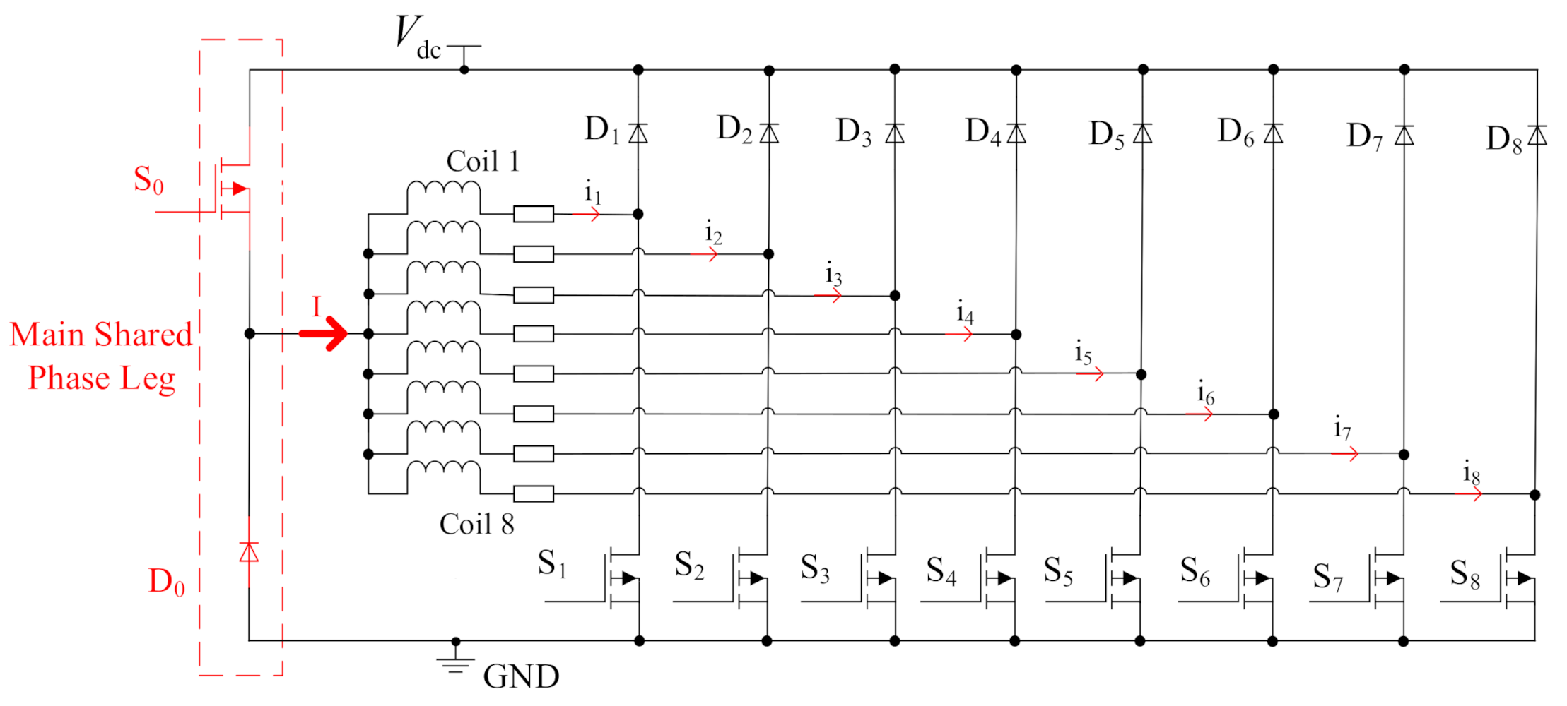
Figure 1, and one axial AMB with a single DOF can form a 5-DOF AMB system to levitate a rotor completely. The rotor can also be supported by only two radial AMBs, and the axial DOF is limited by the coupling connecting the motor to the transfer torque, thus a 4-DOF AMB system is built. A 4-DOF AMB system has 8 coils in total and needs 8 full-bridge circuits, as shown in
Figure 3, so it needs 32 power switches and 32 isolated drive circuits, which greatly increases the failure rate of the SPA and reduces the reliability.
Because the SPA of an AMB employs a differential control mode, the winding currents of a pair of coils controlling one axis are equal to the bias current
i0 add and subtract the control current
ic, respectively, changing near the bias current
i0 as the control current
ic changes. Therefore, the winding current only needs to be unidirectional. Saving two switches S
3 and S
4 with their driving circuits, the unidirectional current control of one coil is realized by using the half-bridge topology shown in
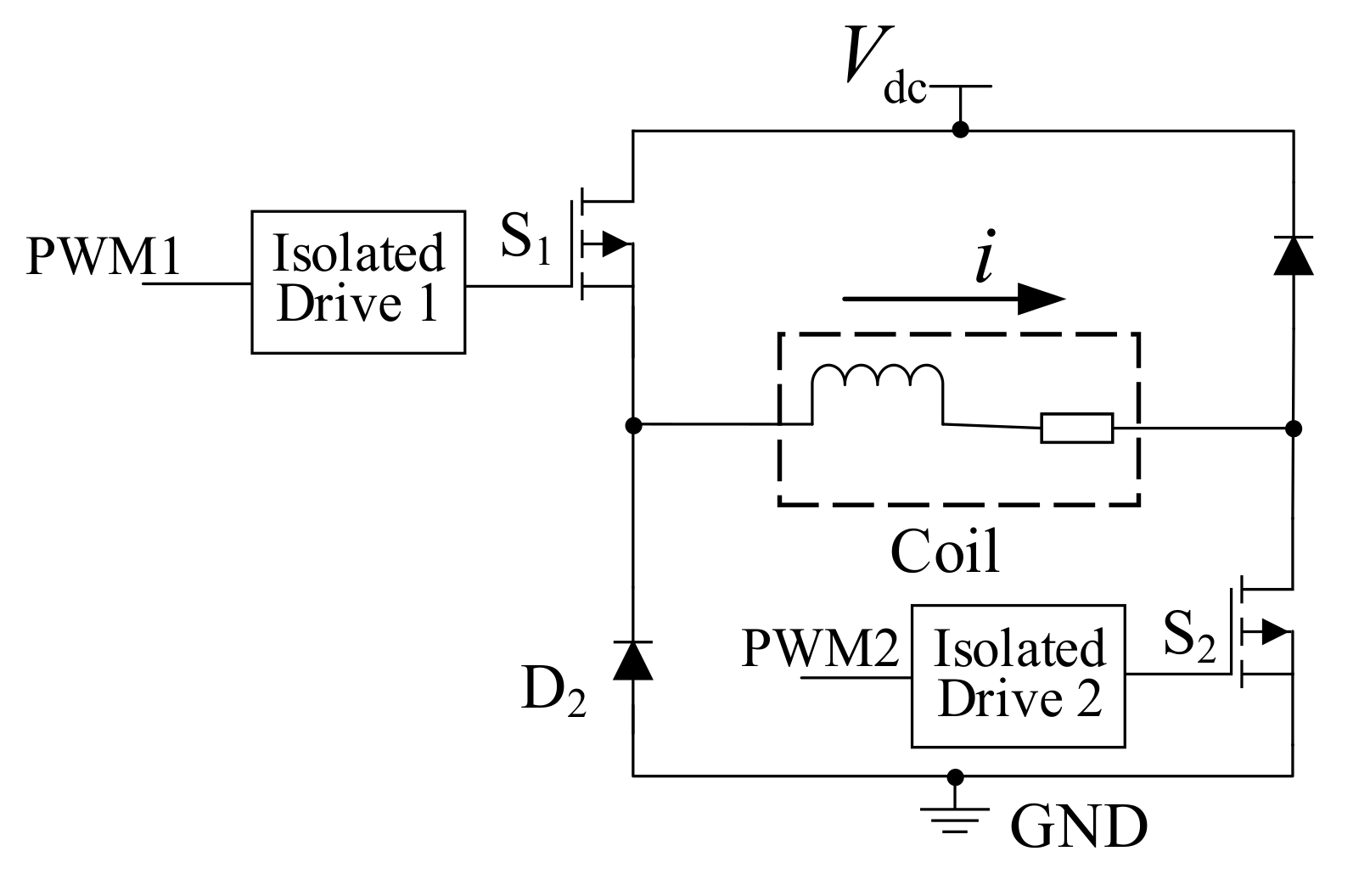
Figure 4. When S
1 and S
2 are opened simultaneously, the coil is charged and the current increases; when S
1 and S
2 are closed at the same time, the coil discharges through diodes D
1 and D
2 and the current decreases; when only one of S
1 and S
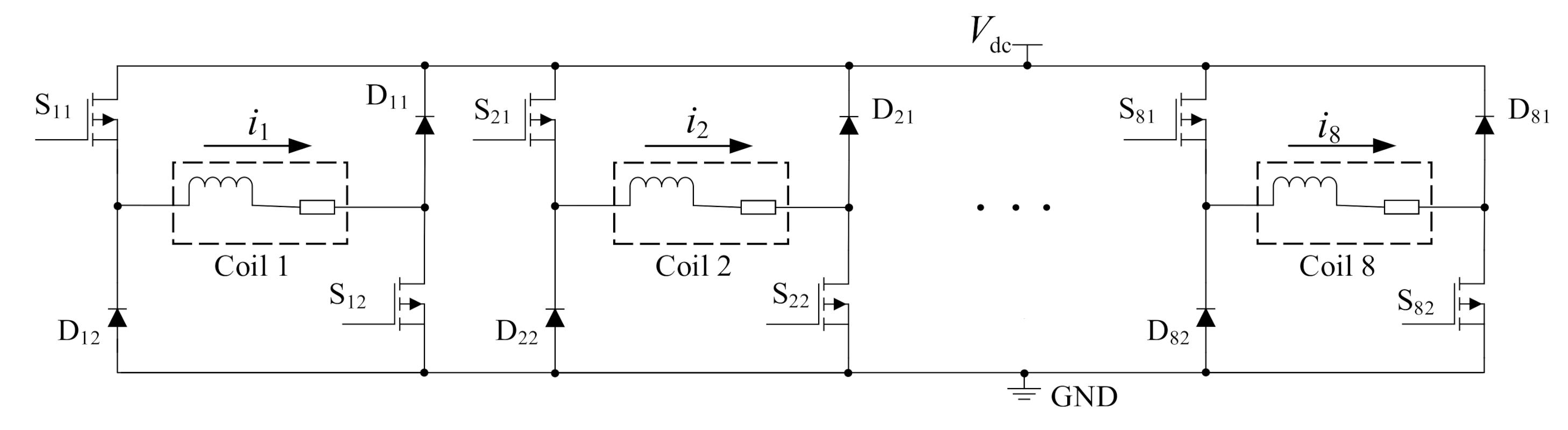
2 is opened, the coil current will freewheel. This topology can save half of the switches and their driving circuits compared with the full-bridge topology. However, one half-bridge circuit can also control only one coil current, and eight half-bridges are required to achieve complete control for the 4-DOF AMB system, as displayed in
Figure 5. Such a large number of components has a high probability of failure, so the dependability of an SPA using a half-bridge topology is still problematic.
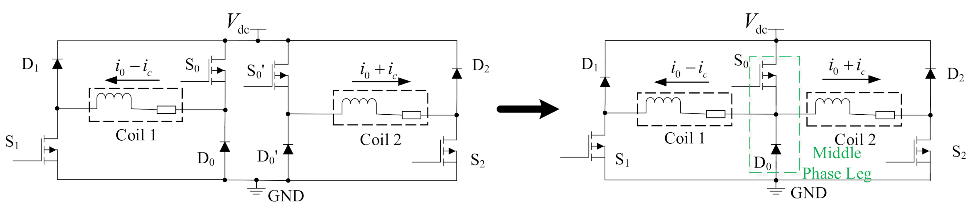
Considering that a pair of coils on one axis of the AMB adopts differential control and their currents have correlation, two half-bridge circuits controlling two coils can be integrated into one three-phase-half-bridge circuit, as shown in
Figure 6, and Coil 1 and Coil 2 are differential coils. The two coils share a middle phase leg, which reduces the use of switch S
0’ and diode D
0’. Although the position of the switches and freewheeling diodes can be exchanged in principle, the switches S
1 and S
2 are generally placed at the low end to simplify the design of power circuits of the isolated drive. Furthermore, the middle phase leg switch S
0 has a fixed duty cycle of 50% to achieve control simplicity, and the change of coil current is realized by controlling the duty cycle of switches S
1 and S
2 on both outer legs [
5]. The current passing through the middle phase leg is the sum of the currents of the two controlled coils, namely twice the bias current, which is exactly equal to the extreme current of either outer phase leg. So, the components on the middle phase leg do not need special consideration, which is why the two coils controlled by the three-phase-half-bridge topology are better as the two differential coils. However, the current flowing through the middle phase leg is constantly twice the bias current, which will bring great challenges to the heat dissipation of the switch S
0. A large bias current may cause the switch S
0 to overheat and burn out. Therefore, when selecting the three-phase-half-bridge topology, the bias current, heat dissipation design and switch S
0 selection should be taken as comprehensive evaluation indexes. When the performance cannot meet the requirements, the ordinary half-bridge topology should be selected.
When applied to multi-axis AMBs, each middle phase leg of the SPA corresponding to each axis plays the same function. By further sharing the middle phase legs and integrating them into a main shared phase leg with a 50% duty cycle, a more device saving topology is obtained [
6]. For a typical 4-DOF AMB, this topology is shown in
Figure 7, where all coils share the same main middle phase leg. Compared with the traditional half-bridge topology, the number of components required is greatly reduced, which improves the dependability of the controller. However, the equipment on the main shared phase leg of this topology must bear a large rated current. The fundamental reason for this is that all coil currents are in the same direction. According to Kirchhoff’s Current Law, the current
I on the main shared phase leg is the sum of the currents of the eight coils:
The switch and freewheeling diode which can withstand high current load must be used in the main shared phase leg, and their lives will still be reduced by carrying a large current. Therefore, the reliability of the SPA with the shared phase leg topology is likely to be much lower than that with the ordinary half-bridge topology.
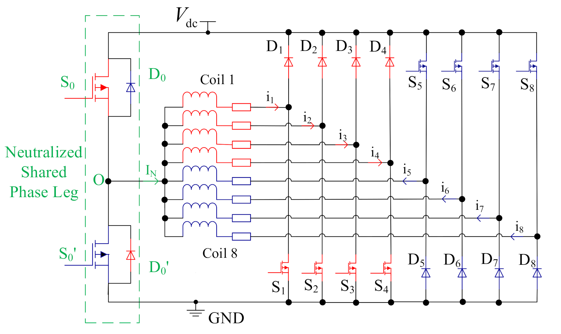
Since the direction of the coil current does not affect the performance of the AMB, half of the coil currents can be reversed at the cost of adding a switch S
0’ and a diode D
0’, as displayed in
Figure 8 [
6]. According to the current direction, the coil can be divided into two groups. The current of the first group of coils (Coil 1 to Coil 4) flows from midpoint O, and the current of the second group (Coil 5 to Coil 8) flows to midpoint O. Therefore, according to Kirchhoff’s Current Law, the current on the main shared phase leg
IN is the difference between the two groups’ currents instead of the sum:
When the magnetically levitated rotor is supported steadily, the rotor only vibrates in a small range near the balanced position. Therefore, the coil current fluctuates in a small range near the bias current, and the current difference on each coil is very small. The current difference between the two groups of coils is also very small. The current of the main shared phase leg is effectively reduced, or neutralized in other words, and the current stress and power loss decrease efficiently.
The neutralized shared phase leg topology greatly reduces the number of components as well as the current stress of the shared phase leg, which can be considered a priority in the design of an SPA of an AMB system. In order to evaluate the SPA topology more comprehensively, this topology is taken as the starting point for more detailed analysis.
3. Coil Pair Arrangement
When the AMB is in stable operation, the winding current only follows the control current in a small range near the bias current, so the current difference between the two groups of coils is very small, close to zero. However, when the AMB system is subjected to severe external disturbances such as the base motion, the air gap between the rotor and the stator has a changing trend of high frequency and large amplitude, and the SPA needs to adjust the coil current sharply to balance the external disturbance. In this case, for the neutralized shared phase leg topology SPA, the current of each coil has a large change, and it will not change closely near the bias current. Then, it is necessary to discuss the coil pair arrangement and evaluate the SPA topology in different forms.
3.1. Coil Pair Arrangement of Different Groups
For SPAs with a neutralized shared phase leg topology, when each pair of coils controlling each axis of the AMB are separately arranged in two different groups, and the current in the two coils is apparently the bias current
i0 add or subtract the control current
ic, the current stress of the neutralized shared phase leg is analyzed, and the basic parameters of the analyzed SPA are shown in
Table 1.
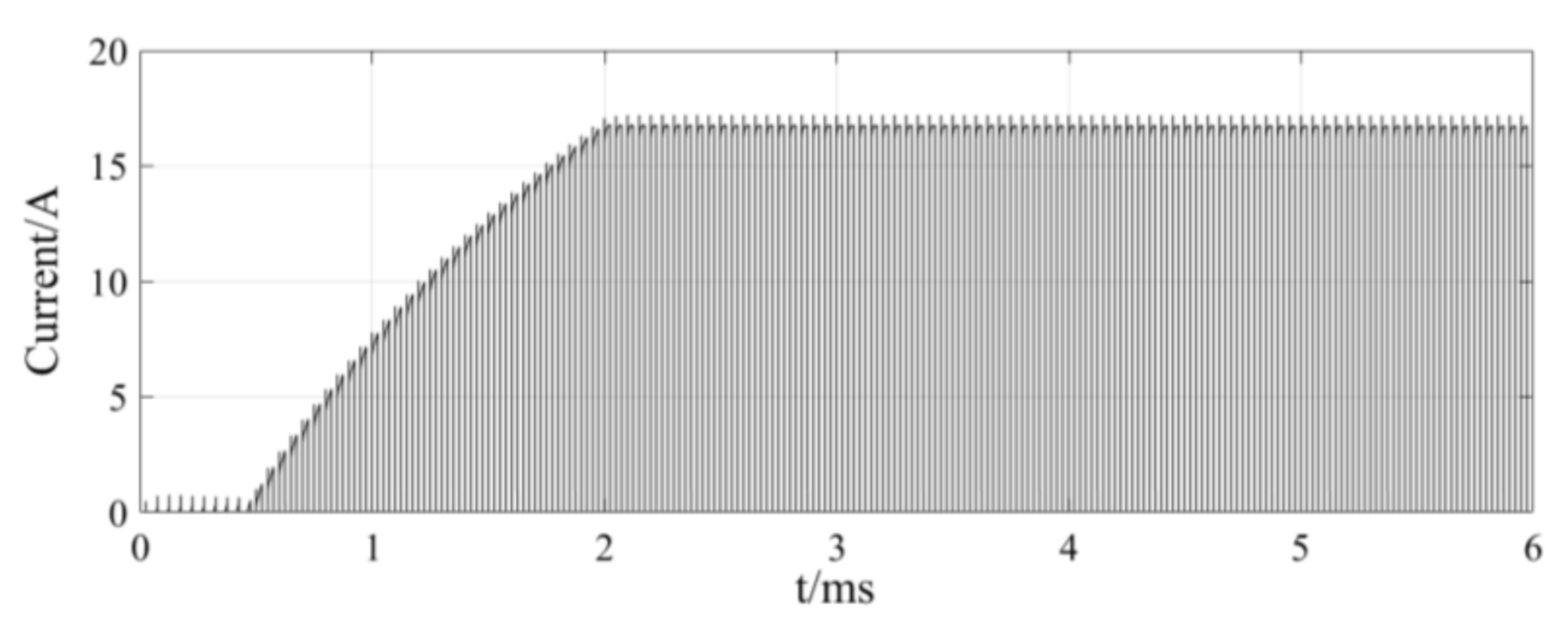
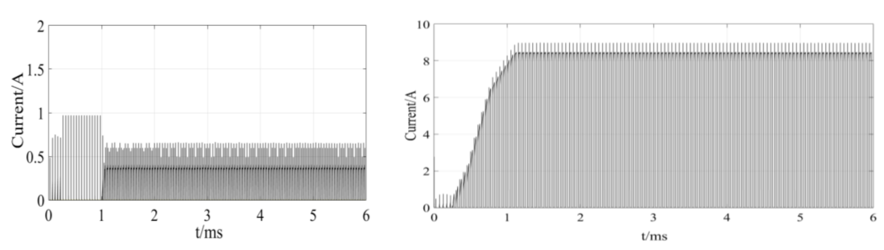
Assuming a special case as an example, the bias current
i0 = 4 A, and the control current of every axis is exactly
ic = 2 A at a certain condition. The coil currents of the first group are all equal to
ij = 2 A, (j = 1, 2, 3, 4), and the currents of the second group are
ij = 6 A, (j = 5, 6, 7, 8). Theoretically, the current on the neutralized shared phase leg will reach about 4 × (6 − 2) A = 16 A. The numerical simulation results are shown in
Figure 9. The simulation results are consistent with the theoretical analysis, which verifies the high current stress of the neutralized shared phase leg. The current spike is caused by switching noise.
Moreover, this is still not the most severe case. If the external disturbance is particularly large, the current of a pair of coils may reach 0 A and 8 A at the bias current of 4 A. Therefore, the current difference between the two groups of coils in the 4-DOF SPA with a coil pair arrangement of different groups will be particularly large, and the devices on the neutralized shared phase leg will not only have a short life but are also very likely to fail, which seriously threatens the normal operation of the AMB system. To avoid the destructive influence of SPA failure under an external disturbance on the stable operation of AMBs, an SPA with a coil pair arrangement of different groups is not suitable to implement the neutralized shared phase leg topology. In order to ensure the reliability of the SPA, the three-phase-half-bridge topology, or even the ordinary half-bridge topology, is to be considered.
3.2. Coil Pair Arrangement of the Same Group
When a pair of coils controlling the single axis of the AMB are arranged in the same group, a group of coils is composed of two pairs of differential coils. Under the differential control, no matter how the air gap between the rotor and the stator changes, only the control current changes, but the sum of the two coil currents of one axis is equal to twice the bias current. For the 4-DOF AMB, four coils of two axes are taken as one group, and four coils of the other two axes are taken as the other. Then, the current of either group is invariably four times the bias current i0, and the current on the neutralized shared phase leg is pretty small. Under this circumstance, the large current stress of the neutralized shared phase leg caused by severe external disturbance disappears, so the neutralized shared phase leg topology possessing the least components is the best choice for high dependability.
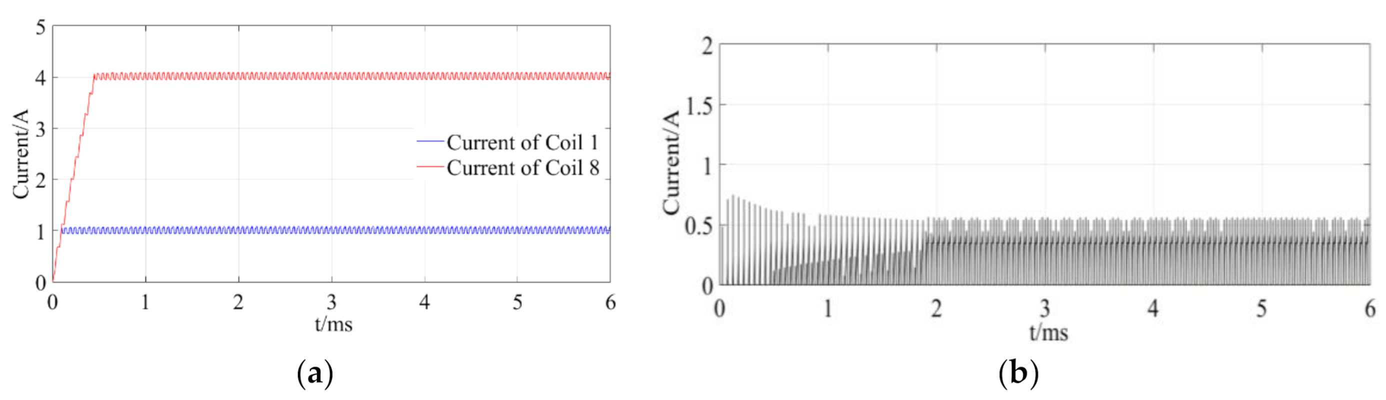
The performance of the neutralized shared phase leg topology with a coil pair arrangement of the same group is simulated and analyzed. The results are revealed in
Figure 10. In order to verify the basic function of the SPA with this arrangement in accurately tracking the reference current signal, Coil 1 and Coil 8 are energized with a current of
i1 = 1 A and
i8 = 4 A, respectively, as shown in
Figure 10a. It is seen that the SPA can realize the basic function of tracking current.
Figure 10b shows that when the bias current
i0 is 4 A, the control current
ij of all four pairs of coils is 2 A, (j = 1, 2, …, 8), the current on the neutralized shared phase leg is almost equal to zero, and the current stress is greatly relieved, which verifies the analysis. Hence, with the coil pair arrangement of the same group, an SPA with a neutralized shared phase leg topology has the advantages of stable performance and high reliability, and is the first choice of design.
4. Bias Current Distribution
Although the previous analysis assumes that the bias current of each coil is the same 4 A, in practical application, the bias current of each coil is not necessarily equal to each other. In a 4-DOF AMB system, the rotation of the magnetically levitated rotor is generally realized by the flexible coupling transferring the torque from the external motor, so the rotor ends can be generally divided into drive-end and non-drive end. The drive-end of the rotor is directly connected to the flexible coupling, which means that the flexible coupling can provide additional stiffness and damping for the drive-end of the rotor. Therefore, under the same working conditions, the electromagnetic force required by the drive-end is less than that of the non-drive end, and the control current of the AMB at the drive-end is less than that at the non-drive end. In the design process of the AMB, in order to save energy and prolong the life of components, the bias current of the AMB at the drive-end is smaller than that at the non-drive end.
In addition, the bias current of each axis is positively correlated with the anti-interference ability in that direction. The AMB in the direction with large disturbance needs to have larger bias currents to generate greater electromagnetic force to balance the external disturbance. Consequently, in the design process of the AMB system, special attention needs to be paid to the maximum forces required by AMBs in all directions, and then taking it as the design basis of the bias current of each coil in the SPA.
In order to study the influence of different bias current distributions on the performance of a neutralized shared phase leg topology SPA, it can be assumed that the bias current of the AMB at the drive-end on the
X and
Y-axis coils is set to 1 A and 2 A, respectively, after considering the influence of coupling and external disturbance, and the bias current of the non-drive end AMB on the
X and
Y-axis is set to 3 A and 4 A, respectively. According to the analysis in
Section 2, the difference in the bias current between the two groups of coils should be as small as possible to mitigate the current stress on the neutralized shared phase leg. Therefore, the coils of 1 A and 4 A current are assigned into one group, and the coils of 2 A and 3 A current are distributed to the other group. The current on the neutralized shared phase leg is simulated and compared with the two distributions of bias current, as demonstrated in
Figure 11.
Figure 11 illustrates that the simulation results are consistent with the theoretical analysis. In order to preferentially apply a neutralized shared phase leg topology, the coils with an unequal bias current should be distributed in the two groups as evenly as possible, so that the current stress on the neutralized shared phase leg is the minimum and the SPA has the highest reliability. Furthermore, if the current stress of the neutralized shared phase leg is still too high, the three-phase-half-bridge topology or even the ordinary half-bridge topology should be considered.


