1. Introduction
The electro-hydraulic servo actuation is a well-developed technology. Nonetheless, most of its physical understanding and mathematical modeling have been referred to the Hydraulic Control Systems by H.E. Merritt as early as in 1967 [
1]. In most cases, it was assumed that the driven load had sufficiently high structural resonances and was modeled as a lumped mass directly attached to the piston rod or motor shaft, with the hydraulic natural frequency dominating the control loop. However, in aerospace applications, such as rudders, fins and engines, due to weight and space limitations, the structural stiffness is usually low, and the model has to be modified. This was also discussed in the classic book, where, however, only the dynamics at the motor shaft point was elaborated, with the dynamics at the load end left open for more work [
1] (pp. 157–162).
An appropriate model for realistic aerospace applications was presented by J.W. Edward for an aircraft rudder control servo system [
2]. A spring was inserted as the structural compliance into the interface between the piston rod and the rudder. The structural natural frequency, the hydraulic natural frequency and the derived composite hydro-mechanical natural frequency were clearly depicted and incorporated into the model, based on which the rudder surface dynamics was controlled by the Dynamic Pressure Feedback (DPF) method and matched well with the test results. The concise approach has been accepted so far [
3] (pp. 35–37), but not widely enough, as seen by the author. In most current publications on electro-hydraulics, only the hydraulic resonance is included [
4,
5]. Furthermore, in most papers studying various emerging electro-hydrostatic actuators, where there are also hydraulic cylinders, only the hydraulic natural frequency is considered [
6,
7]. This approach might work well elsewhere but not in highly dynamic aerospace actuators. Moreover, since the digital control is the first choice nowadays, a better model is greatly helpful to understand the underlying physics, to fabricate the control algorithm and to accelerate the development process.
The author’s team has been working on electro-hydraulic actuators to gimbal Chinese non-toxic-non-pollution launcher engines [
8,
9,
10]. In practice, the easy approach by J.W. Edwards has been used and developed with a new application perspective and more details, worthy of being elaborated here. For a variety of actuation systems, a normalized model was developed, in the easy form of a control block diagram written in transfer functions. A one-mass-one-spring model of the structural resonance, including the natural frequency and the damping ratio, as well as its measurement, was described. Inside the piston position loop, there was another second-order transfer function with two zeros and two poles representing the hydro-mechanical composite resonance effect. It was pointed out that the poorly damped and low frequency structural load resonance is the root cause of the poor system stability, rather than the hydraulic resonance, as mostly claimed. A combined control strategy of notch filter, nonlinear proportional, integral and differential (PID) controller and feed-forward compensation was given to meet the stringent requirement of static and dynamic performances. Another two-mass-two-spring model was introduced to deal with the thrust vector control of a heavy launcher engine with a more complex mass and stiffness distribution.
2. The System
A simplified schematics of an aerospace electrohydraulic actuation system to drive a launcher engine is described in
Figure 1. The control loop includes a digital controller, a servo-valve, a double acting piston actuator and a linear displacement sensor imbedded inside the rod. The controller closes the negative feedback loop and performs digital algorithms for static and dynamic compensations. The expected output is the engine’s gimbaling angle. It is a classic aerospace design, where the feedback signal is picked up via the sensor inside the piston rod rather than via the angular output sensor.
3. The System Model
The physical model to connect the actuator and the engine is critical. A one-mass-one-spring model is precise enough to depict most engine dynamics, as in
Figure 2, since the gimbaling inertia is the dominating load.
Though its simplicity is a surprise, it is noteworthy that, in reality, there is neither a real connection spring between the rod and the engine nor a support spring at the actuator body end, even though a real spring exists in most load simulators. The model was found to precisely depict the internal mass distribution inside the engine body and hence its resonance dynamics. In practice, the system is designed in such a way that other structures, like the piston rod, the actuator body and its fixed supporting structure, are so strong that only the stiffness inside the load needs to be modeled.
Once the physics is clear, the mathematical equations are presented in Equations (1)–(4). The symbols are listed in Abbreviations.
To derive a normalized model, the first step is that the load dynamics in Equation (3) has to be changed into a second-order transfer function, as in Equation (5).
Note that the engine’s structural resonant frequency ωL and the damping ratio ξL are independent of any other electro-hydraulic actuator design, except for the installation geometry on which the rotation radius R depends. In ground testing, there are two measure points, one at the piston rod as Xp and the other at the engine gimbaling angular output as XL. Usually, the engine gimbaling angle is measured in the form of linear displacement and converted to the angular value.
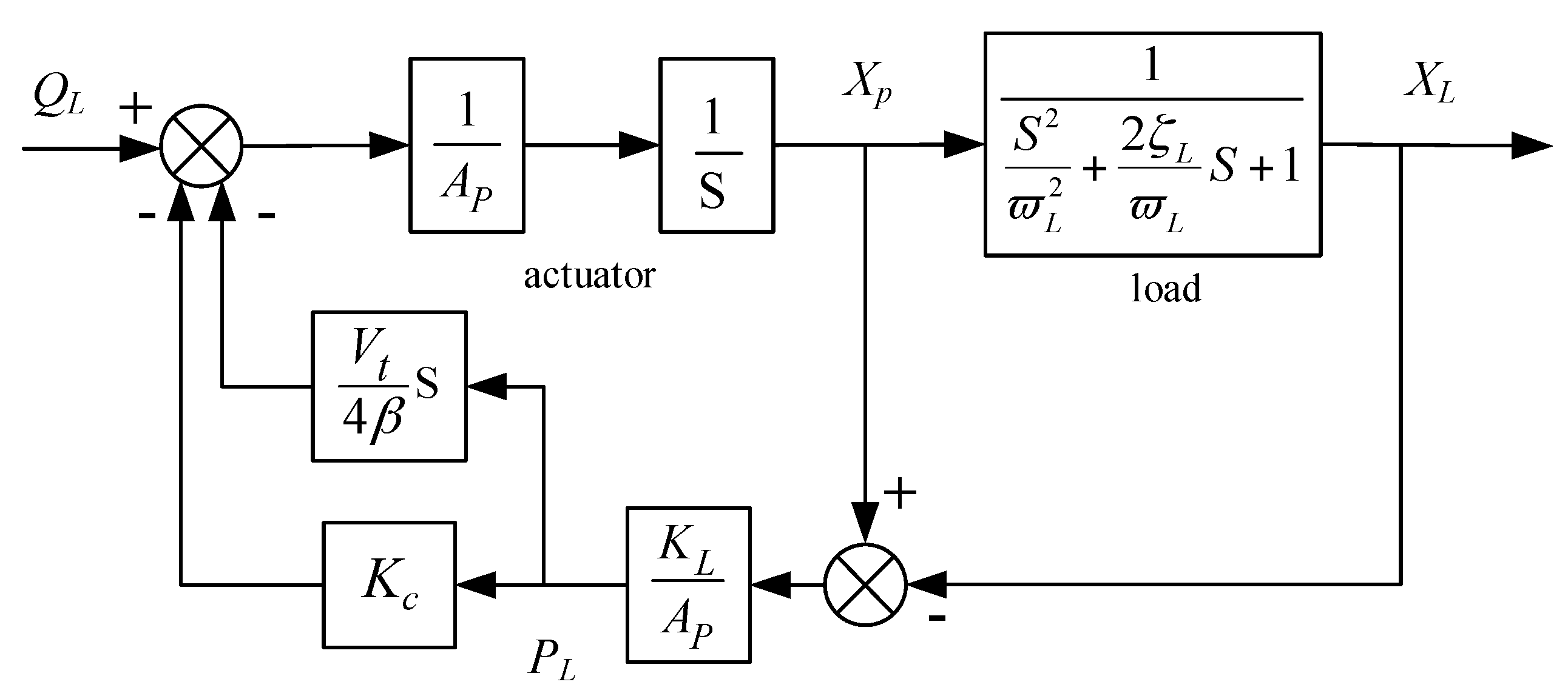
The next step is to represent Equations (1), (2) and (5) into a control block diagram, as in
Figure 3.
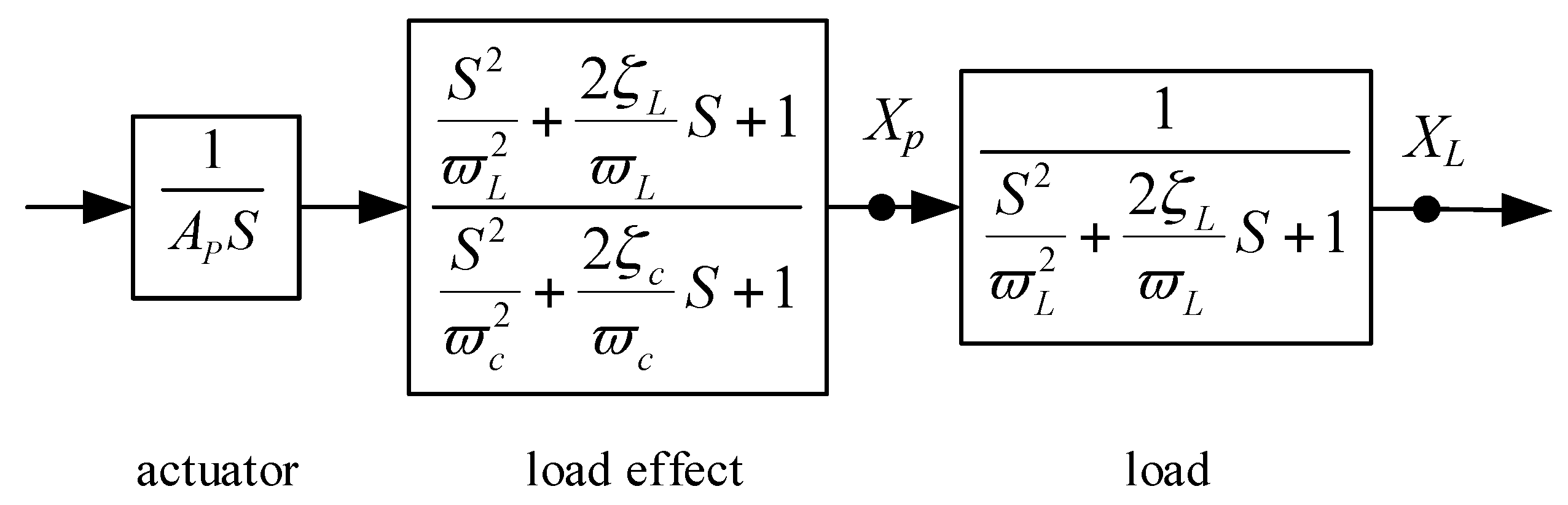
So far, the model derivation in
Figure 3 has been a routine and usually stops here. To get a more concise form, it needs to eliminate the minor loops. Though a little tricky and laborious, it is worth seeing the result, in
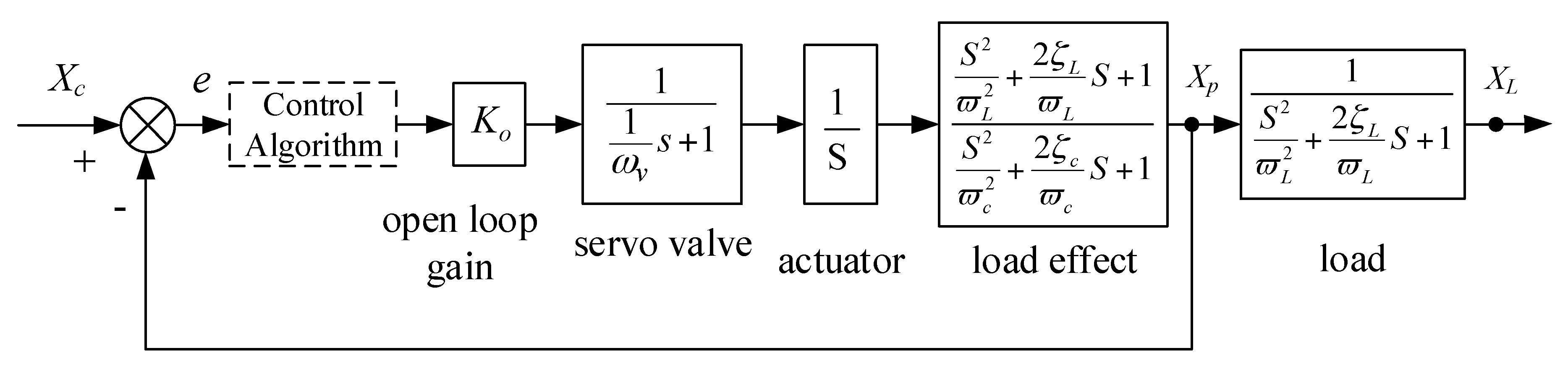
Figure 4, after successful block reductions. With the servo-valve and the controller added, as well as a lumped open loop gain, the final normalized system model is given in
Figure 5.
The servo-valve is modeled as a first-order transfer function in that its bandwidth is chosen to be much higher than the structural resonance. The other underlying equations are given in Equations (8)–(12).
As can be seen, for the expected output XL, it is only a half-closed loop. Inside the piston position Xp loop, a second-order transfer function with two zeros and two poles dominates, both poorly damped, representing the hydro-mechanical composite resonance effect arising from the coupling between the load structural resonance and the hydraulic resonance, simply called “load effect”.
Since the structure natural frequency ωL is low, the acting piston area Ap has to be large, so that the hydraulic natural frequency ωh is much larger, often at least three times as large as ωL. The resulted composite frequency ωc in the denominator is a little smaller than the load natural frequency ωL.
Inside the loop, the second-order numerator is helpful to cancel out the hydro-mechanical resonance effect of the second-order denominator. However, there is still another second-order denominator outside the loop, representing the load structural resonance. Therefore, both inside and outside the loop, there are two second-order denominators but only one second-order numerator. As a result, at least another second-order numerator is needed for the system’s stability. Without any compensation, a higher open loop gain would definitely lead to serious vibrations. In the real world, disastrous resonance would accompany the destruction of these structures.
In a word, the poorly damped and low-frequency structural load resonance is the root cause of the poor system stability, rather than the hydraulic resonance, as mostly claimed.
4. The Control Algorithm
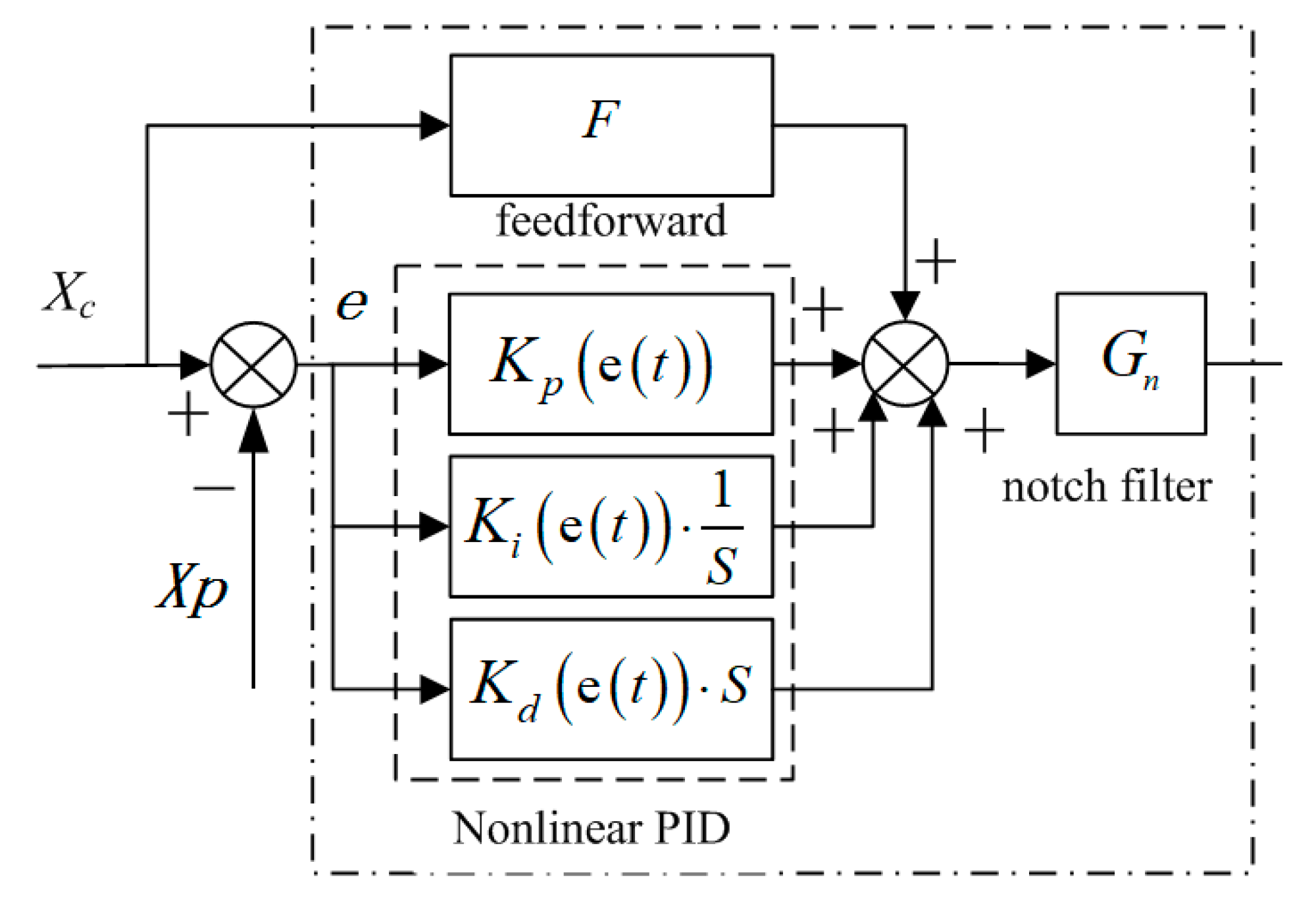
A combined control strategy was developed as
Figure 6.
The control algorithm comprises three parts: a notch filter, a nonlinear PID and a feed-forward compensation.
The notch filter function
is used to effectively suppress the system resonance, shown as Equation (13).
The rationale is that the poorly damped poles (ωc, ξc) are cancelled out by a pair of nearly poorly damped zeros (ωn1, ξn1) in the numerator and replaced with a pair of better damped poles (ωn2, ξn2). It can be as simple as ωn1 = ωn2 = ωc, ξn1= ξc, ξn2 = 0.2~0.4, and usually ξr ≈ 0.03~0.1, ξr ≈ ξc + 0.01. In practice, the can be optimized to change the width and depth of the notch window.
The nonlinear PID is used to improve the tracking accuracy in the low frequency band, i.e., around 1~5 rad/s, with a piecewise proportional gain presented as Equation (14).
A higher gain near zero is used to deal with the nonlinearities at the servo-valve spool center. The differential factor is usually small and helps to overcome the stiction forces in the system. As to the integral factor, it helps to improve the positioning precision and needs to be set as active only when the hydraulic power is on, so that an integration saturation and thus a jittering at the startup can be avoided.
A reduced-order feed-forward compensation is given as Equation (15).
In the intermediate frequency band, some distance from both the high frequency structural resonance region and the low frequency region, a higher open loop gain Ko is needed for high precision velocity tracking. However, even with a notch filter, there is a limit to increase the magnitude of Ko, e.g., one third of the structural natural frequency ωc, so that a reduced-order feed-forward compensation is of great help to reduce the phage lag in this frequency region. The underlying principle is that, with higher and lower frequency components roughly neglected, there is only one integral transfer function left in the closed loop, which can be cancelled out by a differential counterpart represented as the feed-forward compensation.
As described above, with a combined control strategy, the system vibration due to structural resonance should be well suppressed while a satisfactory frequency response in the whole frequency region from low to high could be obtained.
5. Simulations and Experiments
An electro-hydraulic servo actuator to drive a high thrust liquid-hydrogen-liquid-oxygen launcher engine is illustrated here, with the main parameters shown in
Table 1.
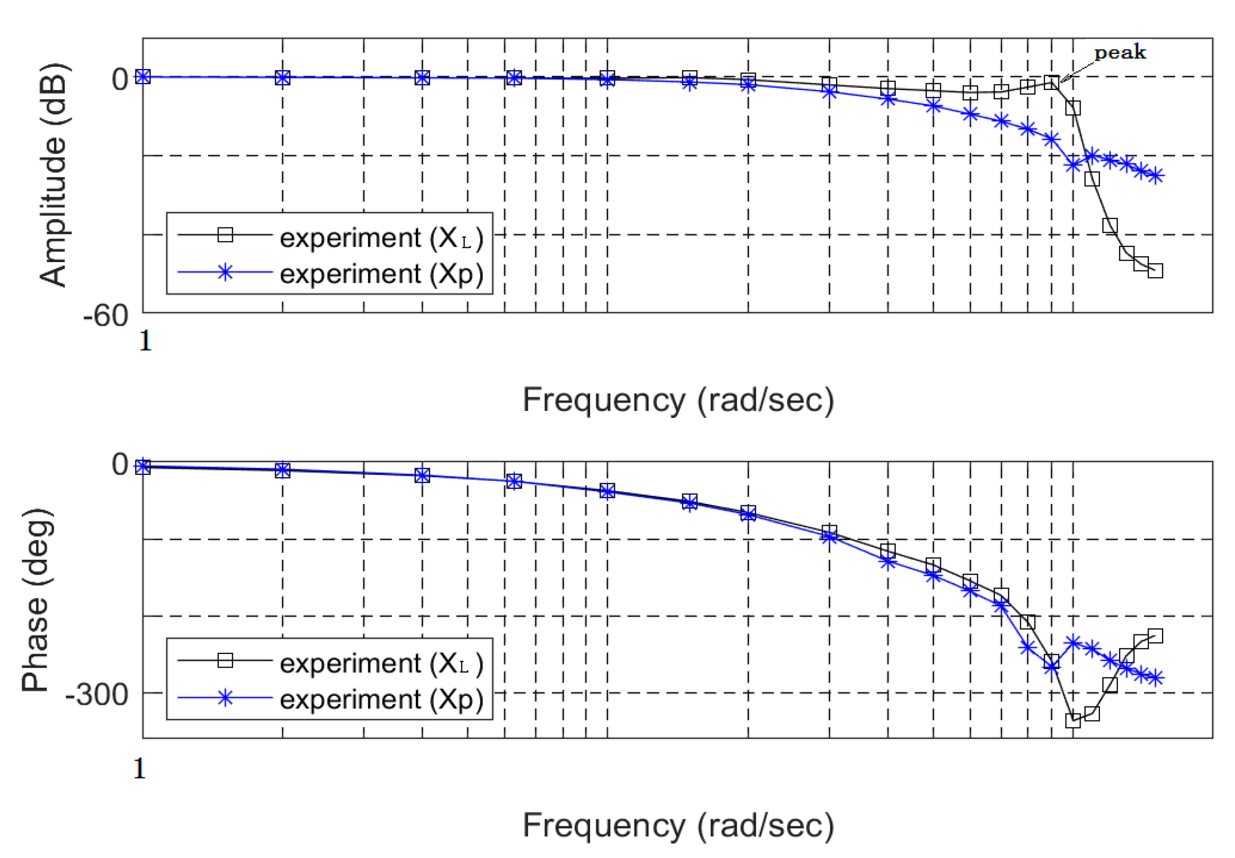
With only an open loop gain of 15 rad/s and without any other compensation, given a series of sinusoidal commands, the system was tested to study the load resonance effect, with bode plots of
XL and
Xp shown in
Figure 7.
It is worth noting that, without compensation, with a small open loop gain, the system has a tendency to vibrate, as shown by the amplitude peak of the load response XL. It is clear that the system has to be compensated for a bigger gain and better dynamics.
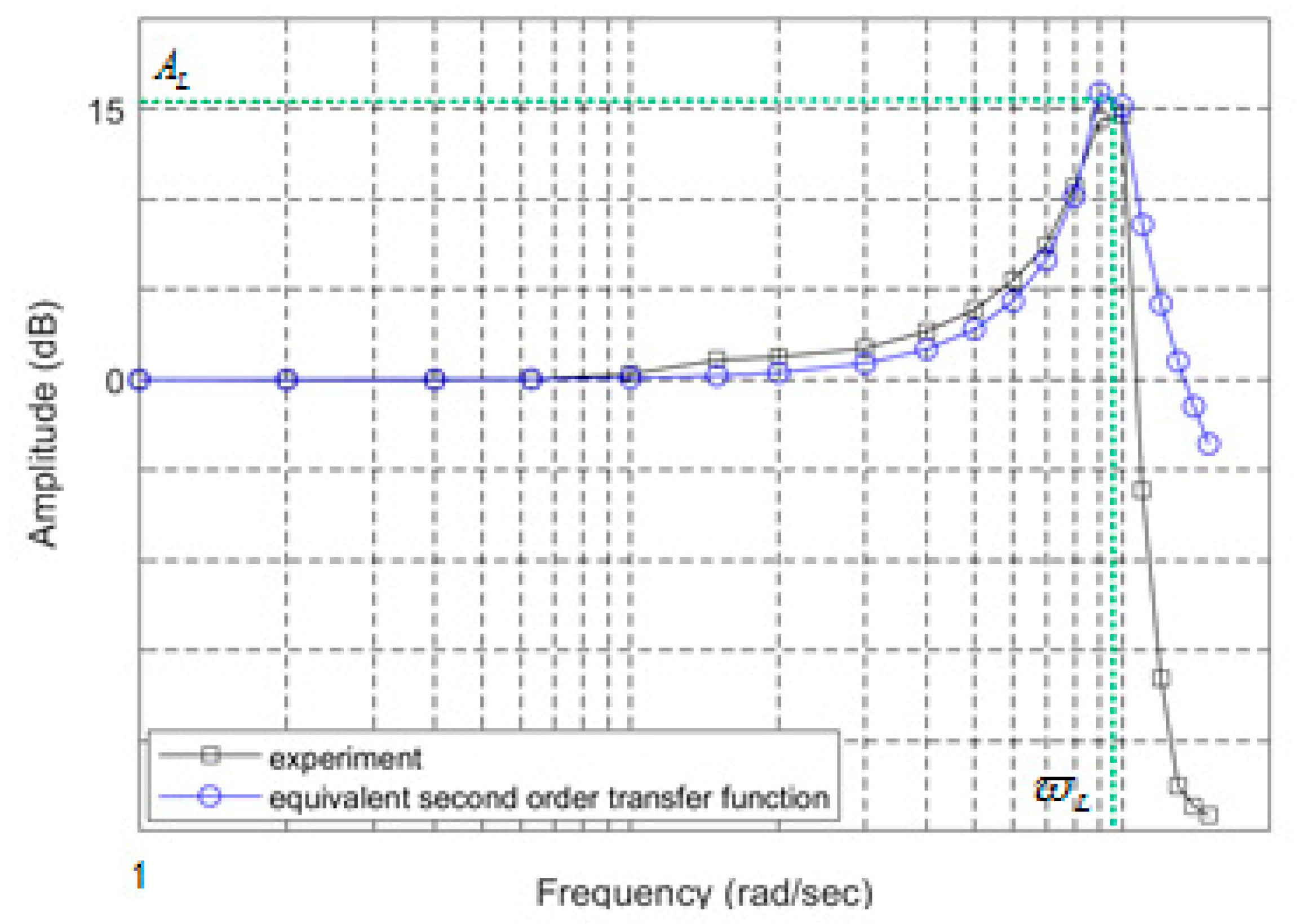
The engine’s structural resonance dynamics can be obtained by directly subtracting the response of
Xp at the piston point from that of
XL at the load output in
Figure 7, resulting in a curve shown in
Figure 8, together with a simulation by a standard second-order transfer function.
As shown, the load resonance can be modeled as a second-order transfer function with a sufficient precision. The structural natural frequency
ωL can be easily identified, while the natural damping ratio,
ξL can be computed by Equation (16).
As the peak amplitude shown is 15 dB, accordingly, the damping ratio is 0.089.
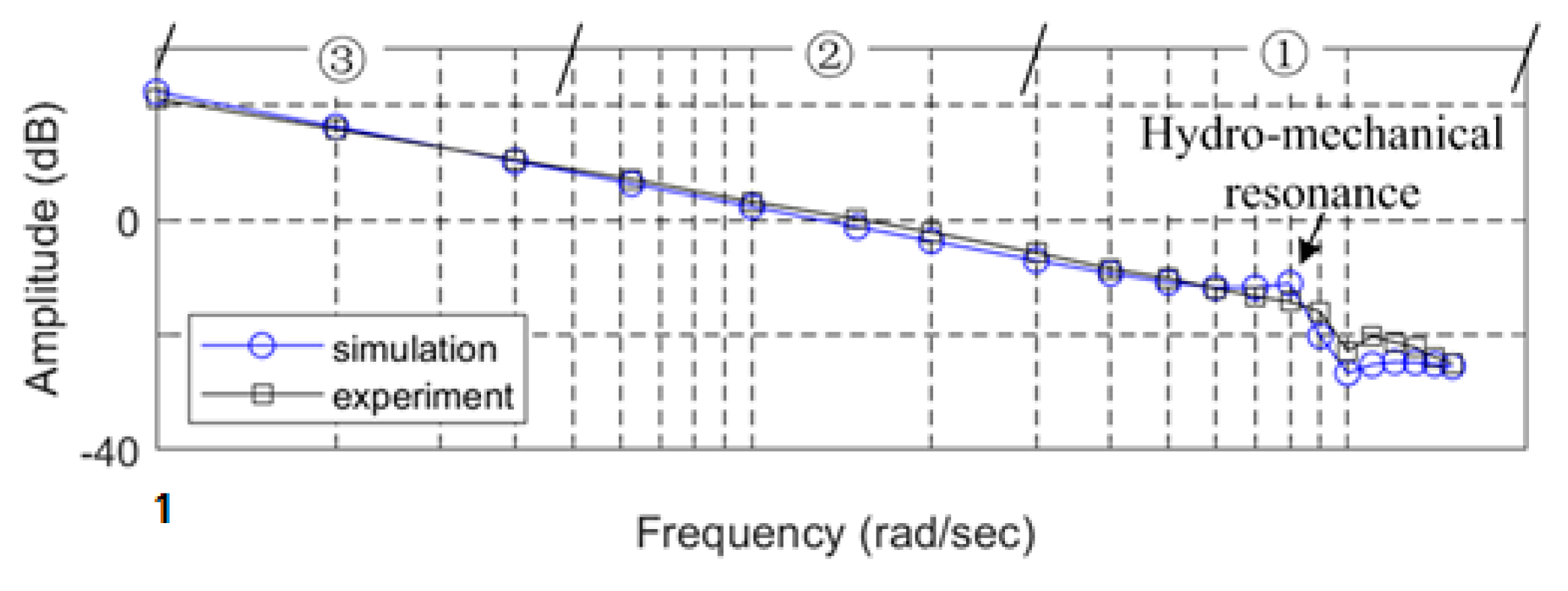
To observe the hydro-mechanical resonance effect, we calculated the open loop response
Xpo by breaking the closed loop response
Xp, with the method shown in Equations (17) and (18), where the response was represented in a complex form. The calculated bode plot is given in
Figure 9.
It can be seen clearly that the hydro-mechanical resonance peak in the amplitude curve is the bottle neck to increase the stability margin. While the DPF was traditionally used to suppress the resonance, with the digital control at hand, a notch filter is the most straightforward and effective approach.
Also as in
Figure 9, there are three regions marked to illustrate the combined control strategy. While the notch filter deals with the resonance in the high frequency region ①, a higher gain and the feed-forward compensation improve the velocity tracking precision in the intermediate frequency region ②, and the nonlinear PID upgrades the response in the low frequency region ③.
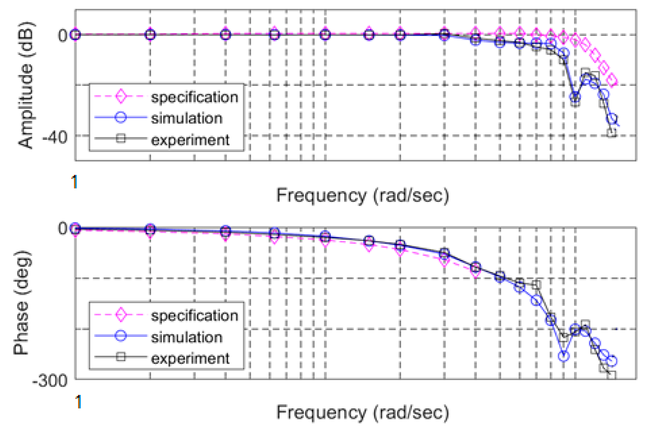
With the combined control algorithm, the final compensated load frequency response
XL is shown in
Figure 10, where the open loop gain was increased to 25 rad/s. The parameters in the PID and feed-forward compensation were optimized around the nominal point. The response data at the marked frequencies in
Figure 10 are listed in
Table 2.
6. A Modified Model and its Control Strategy for A More Complex System
While a one-mass-one-spring model is sufficient for most aerospace loads, there has to be some modifications for a high thrust liquid-oxygen-kerosene engine, since it has a more complicated mass and stiffness distribution [
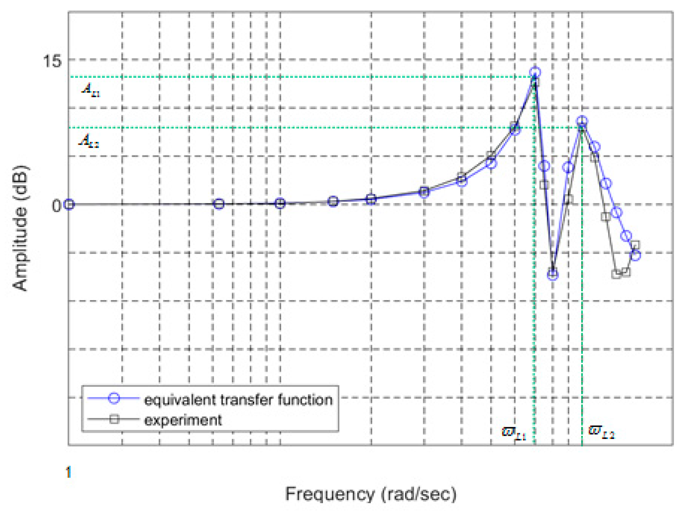
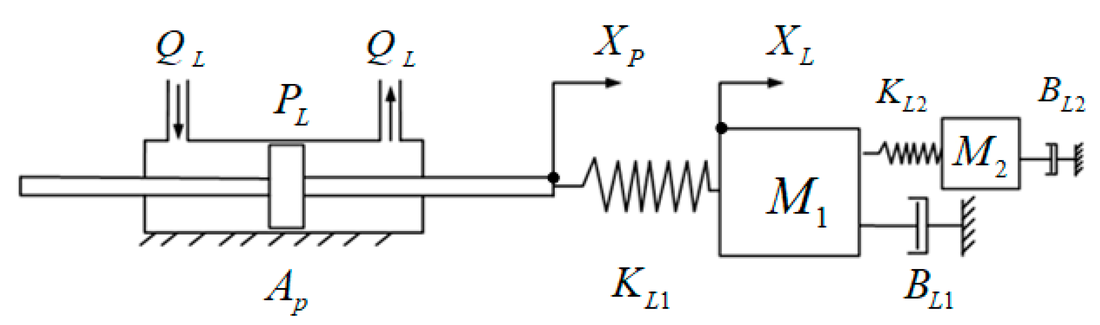
11]. It has two apparent structural natural frequencies, so that a two-mass-two-spring model has to be used. The tested structural dynamics was plotted and compared with the simulation in
Figure 11. The two-mass-two-spring physical model is depicted in
Figure 12.
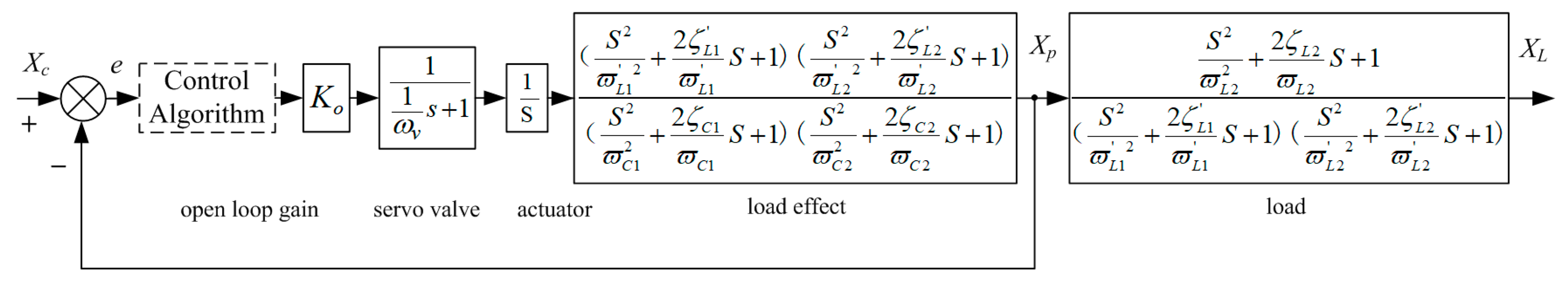
The corresponding normalized system block diagram was derived as
Figure 13, where there are representations similar to those in
Figure 5 but with an additional structural resonance and an additional corresponding composite hydro-mechanical resonance. Since the two structural resonance frequencies are near each other, neither can be ignored, and both have to be treated with carefully.
As in the control algorithm, in
Figure 6, two rather than one notch filter were used as Equation (19).
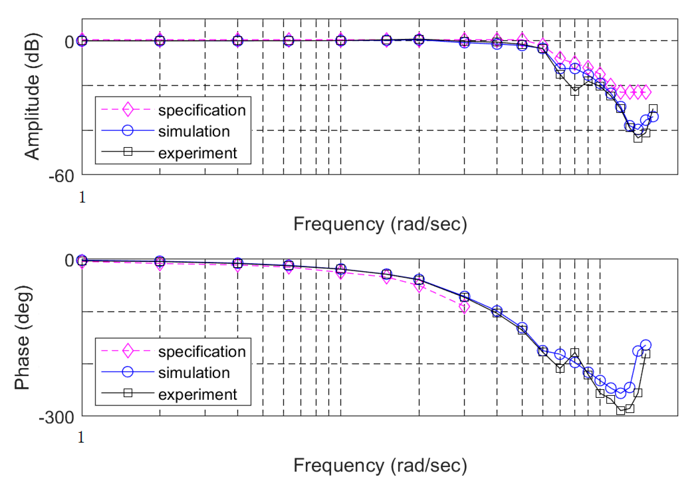
Again, with the combined control algorithm, the satisfactory dynamics was obtained as shown in
Figure 14.
7. Discussions
As shown above, unlike some applications where only the hydraulic resonance is cared, the load structural resonance cannot be ignored in an aerospace electro-hydraulic actuation system that needs to be as fast as possible. There is no reason why, in a highly dynamic actuator, the hydraulic natural frequency given by the design should be lower than that of the controlled target. Therefore, the load structural natural frequency becomes the lowest in the system and is the dominating design constraint.
One may argue that there should be no structural natural frequency
part if the feedback is taken at the engine angular output point, as can be easily seen in
Figure 4 and
Figure 5, in that it would be cancelled out. Nonetheless, there is the composite hydro-mechanical part left with the natural frequency
. Because
is derived from
and
, as in Equation (10), it is clear that the structural natural frequency
is still the lowest and the ceiling to limit dynamics.
Since the demanded system bandwidth is approaching the structural natural frequency, a combined control algorithm has to be carefully designed, here comprising a notch filter to suppress the resonance in the high frequency region, a feed-forward compensation to improve the phase margin in the intermediate frequency region and a nonlinear PID to upgrade the performance in the low frequency region, respectively. Fortunately, a digital control approach was applied, and the seemingly complicated algorithm can be easily implemented in the software. In some applications, even more complicated PID algorithms were used, e.g., an exponential proportional gain in the null region.
With the digital convenience, the parameters in the control algorithm can be defined to be changed easily, when different actuators or engines are used. With the same software package, a couple of actuation systems, e.g., to drive liquid-oxygen-kerosene engines and liquid-hydrogen-liquid-oxygen engines, have completed several flight missions.
Moreover, compared to the traditional DPF method in which electronic or hydro-mechanical devices to sense the differential pressures are needed, the digital approach is more effective, economical, flexible and reliable, due to the reduction of critical hardware.
Lastly, though in the presented systems servo-valves are used, the approach applies to pump-controlled systems in fast moving applications, i.e., electro-hydrostatic actuators (EHA), in which the hydraulic cylinders are used as well.
8. Conclusions
The load structural resonance was measured and represented clearly in a Bode plot. The concise second-order and fourth-order transfer function models were constructed, representing a one-mass-one spring model and a two-mass-two-spring model, respectively. A normalized system model was developed, comprising a closed loop for the piston displacement plus a load structural resonance outside. Inside the loop, the composite hydro-mechanical resonance was modelled and identified by the experiment. A combined control strategy was used to obtain satisfactory dynamic performances in the whole frequency range, from low to high. The experiment data matched well with the simulations, and satisfactory performances were obtained. It was demonstrated that, in a highly dynamic aerospace electro-hydraulic actuation system, the load structural resonance—rather than the hydraulic resonance, as often stated in other applications—is the dominating constraint and should be given priority in the design.


