Proceeding Paper

Numerical Studies on the Design of Self-Resetting Active Bistable Cross-Shaped Structure for Morphing Applications †

1
Structural Engineering Division, Department of Civil Engineering, IIT Madras, Tamil Nadu 300036, India
2
Institute of Structural Analysis, Leibniz Universität Hannover, 30167 Hannover, Germany
3
School of Engineering, Cardiff University, Cardiff CF24 3AA, UK
*
Author to whom correspondence should be addressed.
Presented at the First International Electronic Conference on Actuator Technology: Materials, Devices and Applications, 23–27 November 2020; Available online: https://iecat2020.sciforum.net/.
Proceedings 2020, 64(1), 16; https://doi.org/10.3390/IeCAT2020-08482
Published: 20 November 2020

Abstract

:
Multistable structures that possess more than one elastically stable equilibrium state are highly attractive for advanced shape-changing (morphing) applications due to the nominal control effort required to maintain the structure in any of its specific stable shapes. The aim of the paper is to develop a bistable cross-shaped structure consisting of symmetric and unsymmetric laminate actuated using Macro Fibre Composite (MFC) actuators. The critical snap-through voltages required to change the shapes are investigated in a commercially available finite element package. The use of MFC actuators to snap the bistable laminate from one equilibrium shape to another and back again (self-resetting) is demonstrated. A new cross-shaped design of active bistable laminate with MFC actuators is proposed where the cross-shape consist of four rectangles on the four legs and a square on the middle portion. All the rectangles are made up of unsymmetric laminates, and the central portion is designed with a symmetric laminate. MFC actuators are bonded on both sides of the four legs to trigger snap-through and snap-back actions. An attempt is made to address the possible design difficulties arising from the additional stiffness contribution by MFC layers on the naturally cured equilibrium shapes of cross-shaped bistable laminates.

1. Introduction

Morphing structures are capable of having multiple stable equilibrium states, and they have been proposed as a solution to fulfil multiple roles in various operating conditions. The methods to produce multistable shells have received great attention and are well documented in the literature [1], in which thermal stress-based bistable shells [2,3] and prestress-based bistable shells [4,5,6] are found to be the most common bistable components. Since 1981, ever since Hyer reported [2] the bistable cured shapes of unsymmetrical laminates, extensive works on bistable laminates have been published, especially on the prediction of cured shapes of bistable using analytical approaches [7,8,9,10], and the robust simulation of the snap-through process by finite element analyses [11,12,13,14,15].
Several concepts have been introduced in the past to include multistable components for morphing applications. Diaconu et al. [16] explored the concepts of using multistable elements in a morphing aerofoil by changing the camber, the chord length of the section and using it in an adaptive trailing edge flap. Nonlinear finite element (FE) analyses of different geometries and laminate configurations have been performed to analyze the differences. The idea of changing the camber for the airfoil section seems to be the most suitable as the multistable plates are separated from the aerodynamic surface. However, the snap-through of such multistable plates have been performed by applying concentrated loads, which is impractical to apply in real situations. Mattioni et al. [17] proposed the concept of the tip morphing of a winglet using a multistable panel. The multistable winglet comprised two parts: the outboard section of airfoil consists of an unsymmetric layout [04/904], whereas the inboard part consisted of a symmetric layup [02/904/02]. As the speed of the aeroplane increases, the multistable part snaps from one stable shape to another, resulting in an increased lift. Daynes [18,19] presented a novel design to achieve morphing of a helicopter blade flap using prestressed multistable composite laminates. The flap consists of a stack of six multistable plates with the dimension of 100 mm × 100 mm, that is clamped at a spar located at 85% of the chord length. This provided a smoother camber variation, unlike conventional hinged control surfaces. Arrieta et al. [20] and Kuder et al. [21] investigated composites with different layups in distinct sections to obtain stiffness variability. This work aimed at a distributed compliance for passive load alleviation in a morphing aerofoil, with the main target being to accomplish global shape adaptation by utilizing the stiffness variability showed by multistable plates. Along with the research progress on morphing airfoil structures, the bistable behaviour unsymmetrical laminates structures have also been extensively investigated for various shape-changing applications [22,23,24,25]. Ma et al. [26] investigated a deformable pipe by combining bistable elements with an origami-inspired cube pipe. Later, Hu et al. [27] proposed a novel pattern reconfigurable antenna based on the bistable glass fibre-reinforced polymer (GFRP). Recently, the novel solar tracking model proposed by Zhang et al. [28] used a number of bistable elements to achieve a hexagonal structure showing the potential of bistable elements to achieve specific shape applications.
Due to the difficulties in applying mechanical loads to trigger the snap-through from one stable state to another, the actuators consisting of shape memory alloy (SMA) and piezoelectric composites [29,30,31,32] have been widely employed. Dano explored the concept of using SMA wires to trigger the snap-through of unsymmetric composite laminates [32]. Analysis by Dano and Hyer [32] on the snap-through using SMA reported that the thermal properties of SMAs, especially the phase transformation temperatures, could significantly influence the shape recovery process in a morphing application. Subsequently, the concept of morphing and deployable structures based on a piezoelectric Macro Fiber Composite (MFC) actuator has been presented by Schultz et al. [33] and Tawfik et al. [34]. With the advancements in flexible piezoelectric materials, actuation with MFC actuators is proved as a faster and efficient method to change the shapes of bistable laminates. Even though an efficient prediction of MFC-bonded bistable shapes are well-reported, discrepancies in snap-through voltage prediction by semi-analytical and experimental results are noticed in literature [35]. Works by Anilkumar et al. [36] showed a better correlation of MFC triggered snap-through prediction using finite element analysis with the previously mentioned experimental observations.
The design space of multistable structures can be expanded using the combination of connected bistable laminates. There is only a limited number of works on the design of different combinations of connected symmetric and unsymmetric laminates to achieve specific shape-changing applications. In this research, we try to model an active bistable cross-shaped laminate, where the cross-shape is split into four rectangles on the four legs and a square on the middle portion. The smaller geometries are made into symmetric/unsymmetric laminates. MFC actuators are bonded on both sides of the four legs to trigger snap-through and snap-back actions. Comparison between cool-down shapes with and without MFC actuators are made to understand the effect of additional stiffness contribution from the MFC layers. Subsequently, snap-through and snap-back analyses are performed on the selected lamina-MFC assembly. Further details of the modelling and design are given in the following sections.

2. Numerical Analysis

Finite Element (FE) analysis is performed on a commercially available FE package, Abaqus. The in-depth details of the analysis are given in the following subsections.

2.1. Initial

The initial step simulates the high-temperature regime for laminates by imposing the predefined temperature field to 140 °C. Mesh convergence studies are performed to understand the influence of smaller mesh sizes and suitable mesh size is taken for the analysis. Since MFC actuators are not activated in this step, the contribution of MFC stiffness to the laminate assembly was considerably negligible at this stage.

2.2. Cool Down

The temperature regime of the laminate part was brought down to room temperature by imposing a temperature difference of −120 °C. It was done by imposing the temperature field to 20 °C to the composite laminates. The temperature difference of −120 °C makes the composite laminate deviate from its original alignment in any one of its possible stable shapes. MFCs are kept deactivated in this step as well.

2.3. MFC Activation

Activating MFC to the laminate assembly will make small changes to the deformed configuration of laminate. This is due to the additional stiffness contribution from the bonded MFC layers. The temperature field which simulates the effects of equivalent voltage was given by the command ’Predefined Fields’ in Abaqus modelling. MFC actuators are activated by imposing the temperature field of 20 °C to all bonded MFC layers.

2.4. Snap-Through and Snap-Back

Snap through, and snap-back procedures are performed in snap-through and snap-back steps, respectively. MFC layers bonded in the top and bottom layers are actuated with voltage increments to trigger the snap actions. The orientation of the MFC layers and application of voltage increments play a vital role in determining the snap-through voltages. When the applied voltage is positive, the resulting electric field is aligned with the poling direction, which leads to fibre-direction expansion. Similarly, fibre-direction contraction occurs when a negative voltage is applied. The reason for using two MFCs is that both MFCs induce curvature in the same direction leading to the snap-through event at the cost of lower voltage in each MFC. Snap-back is achieved by reversing the polarity and magnitude of voltage increments on the MFCs from the snap-through step, thereby allowing snap-through from the second stable shape to the first stable shape.

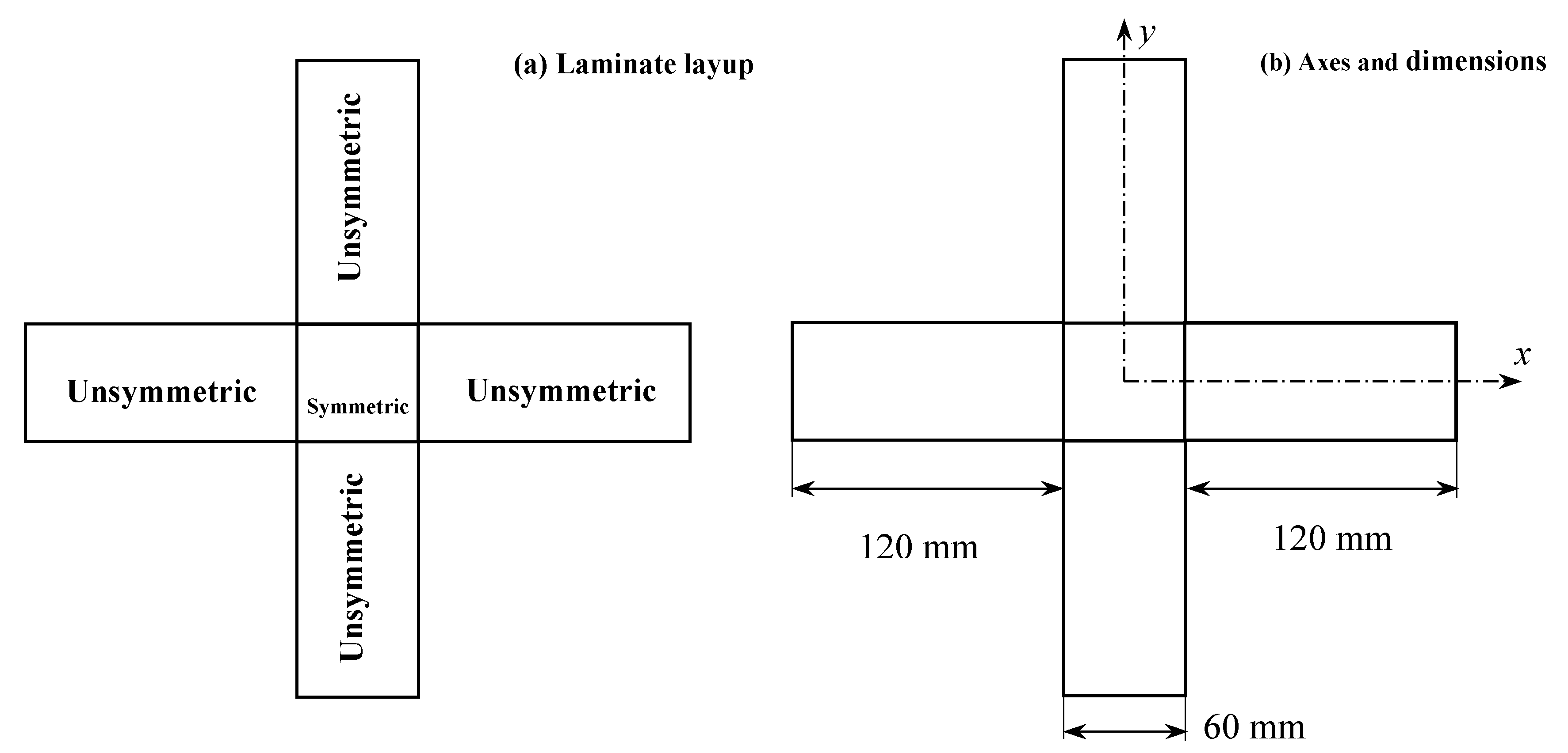
3. Problem Definition

Mechanical and thermal properties of the material used (AS4-3502) for the analysis are given in the Table 1.
In order to design a highly multistable active laminate, a cross-shaped fibre-reinforced bistable laminate is proposed in this study, which has potential as an energy harvester. The geometry considered in the analysis is given in Figure 1.

4. Results and Discussion

The different layups considered for the analysis can be seen in Figure 2. As shown in Figure 2, the primary difference in the design is on the layup used in different legs on the cross-shaped structure. In the first design geometry (Figure 2a), all four legs are taken as [02/902] with a middle portion of layup [04]. In the second design geometry (Figure 2b), two legs are taken as [02/902] and the other two legs are designed with [902/02] with a middle portion of layup [04]. All four legs are connected to the middle section using the TIE constraint option in Abaqus.

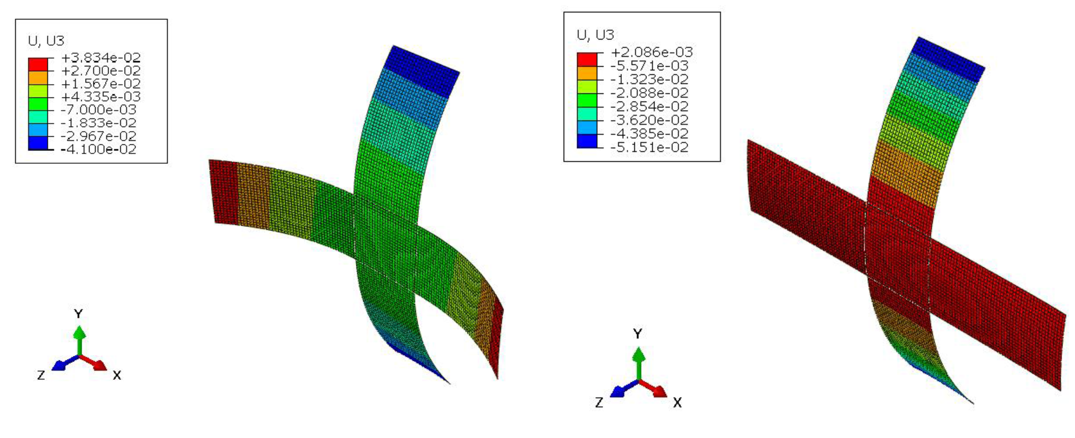
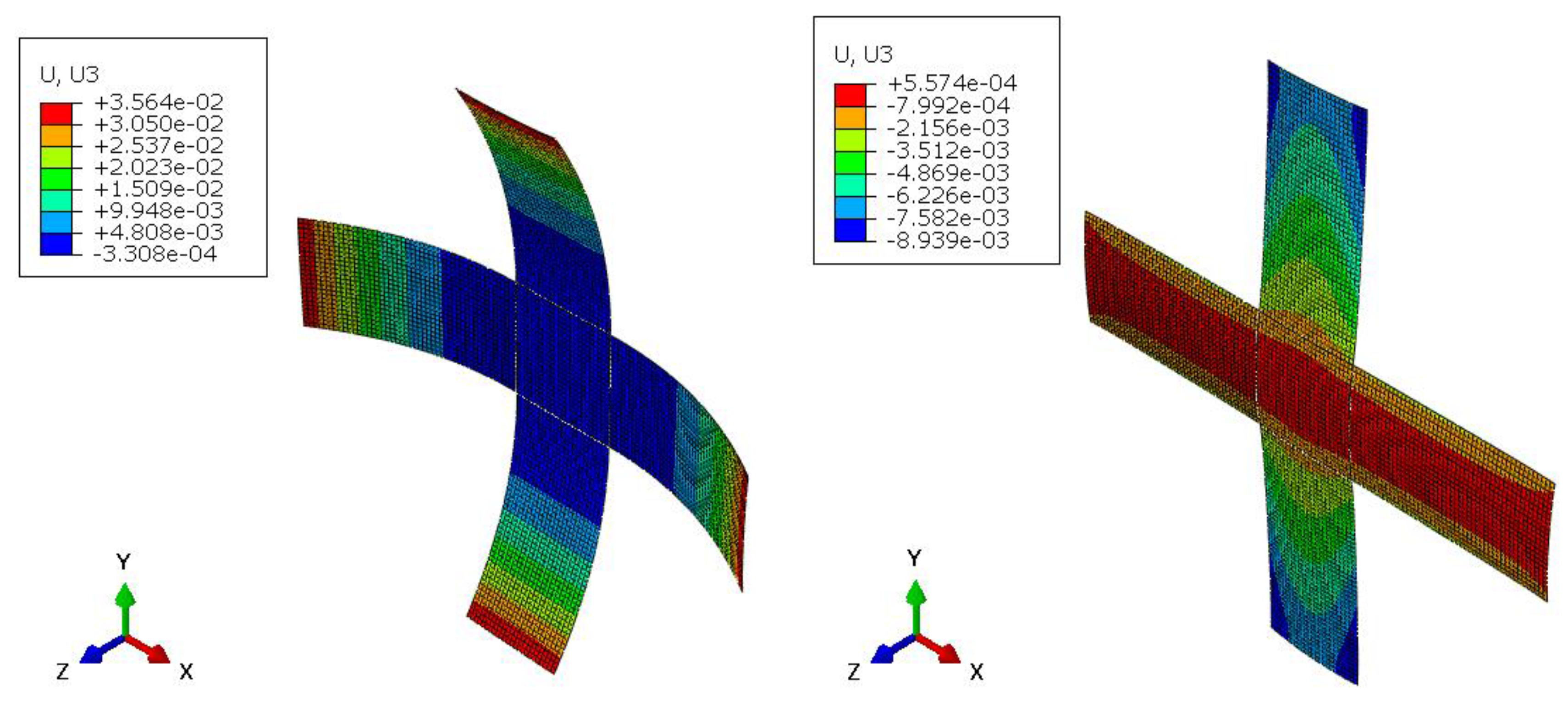
4.1. Cool Down Shapes

Cool-down stable shapes obtained for both geometrical configurations considered are given in Figure 3 and Figure 4. For geometry-1, an undesired shape was observed in one of the stable shapes where curvature developed in two legs (legs along x-x) is found to be opposite in nature to the curvature developed in other two orthogonal legs (legs along y-y). The shapes obtained for geometry-2 are found to be more interesting as one of the shapes is curved, and the other shape is almost flat in nature. The comparison of out-of-plane displacement for both shapes at different locations is given in Table 2.

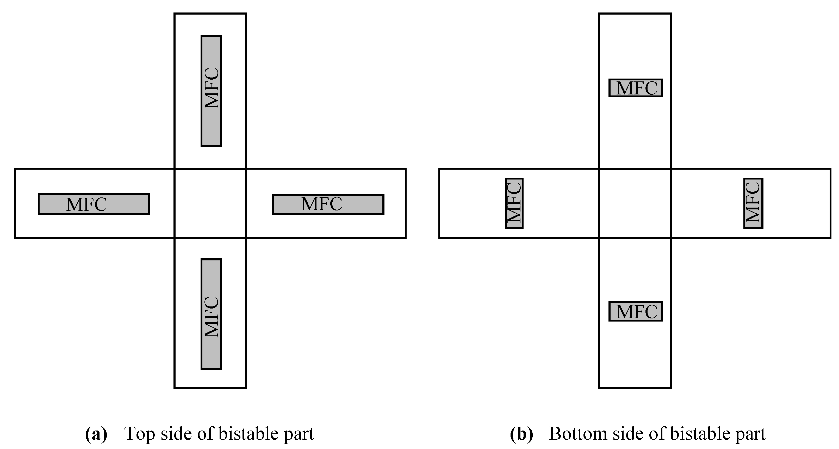
4.2. Selection of MFCs

As mentioned in Section 4.1, for geometry-1, the curvature developed in two legs (legs along x-x) is found to be opposite in nature to the curvature developed in other two orthogonal legs (legs along y-y). Whereas in geometry-2, the curvature developed in two legs (legs along x-x) is found to be similar in nature to the curvature developed in other two orthogonal legs (legs along y-y). Considering the aforementioned observation, geometry-2 is considered for the design of the self-resetting active bistable cross-shaped structure.
The selection of appropriate MFC actuators are very important in the design of active bistable laminates. Small-sized MFC actuators may require very high voltages to trigger the snap-through action. A large-size MFC can cause a reduction in the principal curvatures of the stable shapes due to their additional stiffness contribution. In addition, the bistable plate may lose its bistability with large sized MFC layers. In order to achieve a preliminary design of the self-resetting active bistable cross-shaped structure, a parametric study has been conducted, and a set of MFCs are selected for the subsequent analysis. A design with eight MFC actuators have been chosen, four on either side of the plate. MFCs are bonded to the outstanding legs of the selected cross-shape. Figure 5 shows the MFC alignment considered for the present analysis. Dimensions of MFC actuators chosen for this study are given in Figure 6.

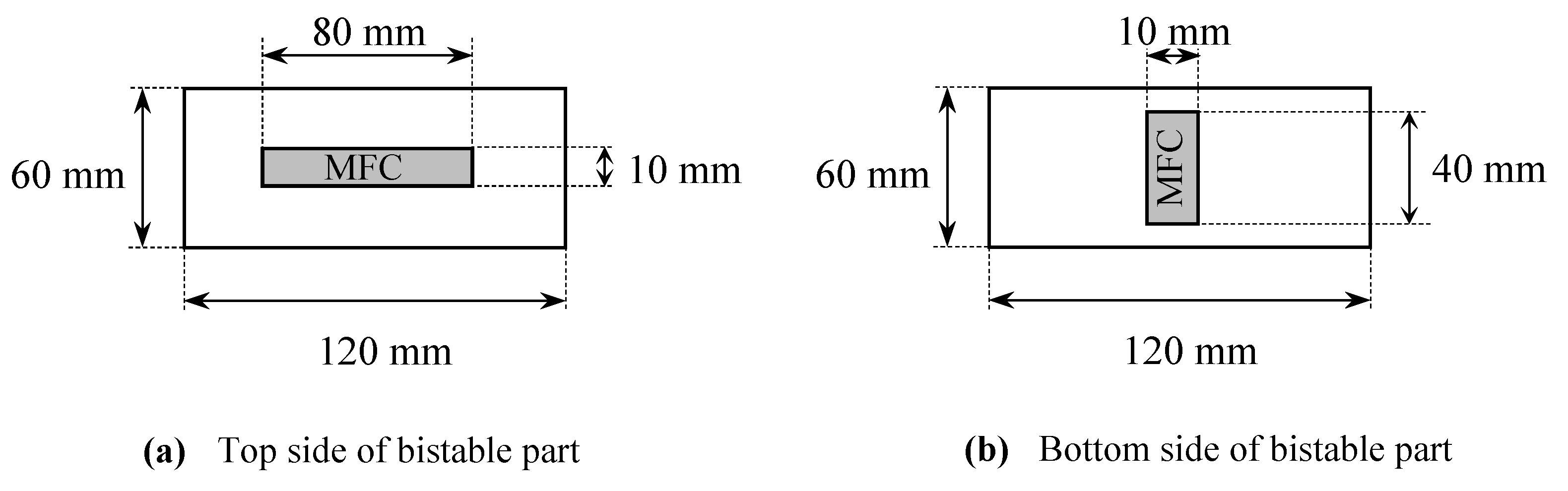
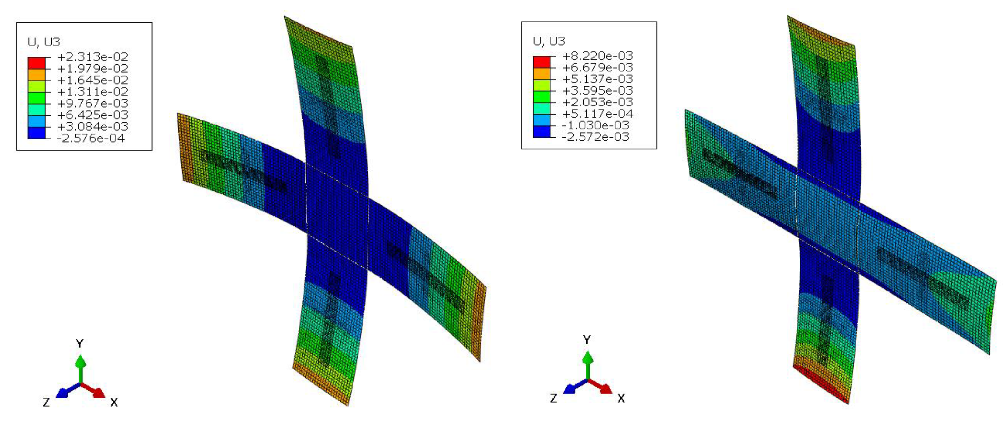
4.3. MFC Bonded Bistable Shapes

MFC bonded bistable shapes obtained for both geometrical configurations considered are given in Figure 7. The comparison of out-of-plane displacement for both shapes at different locations are given in Table 3. As expected, a noticeable reduction in out-of-plane displacement is observed with the addition of MFC layers to the cured bistable shapes.

4.4. Snap-Through Voltages

The snap-through and snap-back voltages of the active cross-shaped laminate (Figure 5) are calculated using the apporoach given in Section 2.4, and are given in Table 4. The calculated snap voltages are higher than the working range of MFC actuators, which may not be practically feasible in real applications. An optimization scheme is recommended to identify suitable positions and size of MFC actuators as the future scope, wherein snap-through should be obtained within the working range of MFC actuators. Extra care should be given in retaining the bistability as it can be disturbed due to the added stiffness contribution from MFC layers.

5. Conclusions

In the present study, the numerical study of an active bistable cross-shaped structure consisting of symmetric and unsymmetric laminate actuated using Macro Fibre Composite (MFC) actuators has been proposed. For the design of the active bistable cross-shaped structure, the cross-shape is split into four rectangles on the four legs and a square on the middle portion. All the rectangles are made up of unsymmetric laminates, and the central portion is designed with a symmetric laminate. Suitable geometrical parameters with two laminate layup sequences are selected for the analysis. The cool-down bistable shapes of both laminate sequences have been predicted. Subsequently, one of the layup is chosen to design the active bistable cross-shaped laminate. Using parametric studies, a set of MFCs are identified to trigger the snap-through and snap-back actions. The size and location of MFCs are selected in such a way that the plate doesn’t lose its bistable property. Snap-through and snap-back analysis are conducted, and the voltage requirements of designed active bistable cross-shaped laminate has been reported. As the calculated snap voltages are higher than the working range of MFC actuators, an optimization scheme is recommended as future scope to identify suitable positions and size of MFC actuators.

Funding

This research received no external funding.

Acknowledgments

Anilkumar P M would like to acknowledge the German Academic Exchange Service: Deutscher Akademischer Austauschdienst- DAAD, and Prime Minister’s Research Fellowship, India during the course of this research.

Conflicts of Interest

The authors declare no conflict of interest.

Abbreviations

The following abbreviations are used in this manuscript:
MFCMacro Fibre Composites
FEFinite Elements

References

  1. Emam, S.A.; Inman, D.J. A review on bistable composite laminates for morphing and energy harvesting. Appl. Mech. Rev. 2015, 67, 060803. [Google Scholar] [CrossRef]
  2. Hyer, M.W. Calculation of the room-temperature shapes of unsymmetric laminates. J. Compos. Mater. 1981, 15, 296–310. [Google Scholar] [CrossRef]
  3. Dai, F.H.; Zhang, B.M.; He, X.D.; Du, S.Y. Numerical and experimentalstudies on cured shape of thin unsymmetric Carbon/Epoxy compositelaminates. Key Eng. Mater. 2007, 334–335, 137–140. [Google Scholar] [CrossRef]
  4. Kebadze, E.; Guest, S.D.; Pellegrino, S. Bistable prestressed shell structures. Int. J. Solids Struct. 2004, 41, 2801–2820. [Google Scholar] [CrossRef]
  5. Daynes, S.; Potter, K.D.; Weaver, P.M. Bistable prestressed buckled laminates. Compos. Sci. Technol. 2009, 68, 3431–3437. [Google Scholar] [CrossRef]
  6. Yokozeki, T.; Takeda, S.I.; Ogasawara, T.; Ishikawa, T. Mechanicalproperties of corrugated composites for candidate materials of flexible wingstructures. Compos. Part A 2006, 37, 1578–1586. [Google Scholar] [CrossRef]
  7. Cho, M.; Kim, M.H.; Choi, H.S.; Chung, C.H.; Ahn, K.J.; Eom, Y.S. A study on the room-temperature curvature shapes of unsymmetric laminates including slippageeffects. J. Compos. Mater. 1998, 32, 460–482. [Google Scholar] [CrossRef]
  8. Pirrera, A.; Avitabile, D.; Weaver, P.M. Bistable plates for morphing structures: Arefined analytical approach with high-order polynomials. Int. J. Solids Struct. 2010, 47, 3412–3425. [Google Scholar] [CrossRef]
  9. Haldar, A.; Reinoso, J.; Jansen, E.; Rolfes, R. Thermally induced multistable configurations of variable stiffness composite plates: Semi- analytical and finite element investigation. Compos. Struct. 2018, 183, 161–175. [Google Scholar] [CrossRef]
  10. Haldar, A.; Groh RM, J.; Jansen, E.; Weaver, P.M. An efficient semi-analytical framework to tailor snap-through loads in bistable variable stiffness laminates. Int. J. Solids Struct. 2020, 195, 91–107. [Google Scholar] [CrossRef]
  11. Schlecht, M.; Schulte, K.; Hyer, H.W. Advanced calculation of the room-temperature shapes of thin unsymmetric composite laminates. Compos. Struct. 1995, 33, 627–633. [Google Scholar] [CrossRef]
  12. Schlecht, M.; Schulte, K. Advanced calculation of the room-temperature shapes of unsymmetric laminates. J. Compos. Mater. 1999, 33, 1472–1490. [Google Scholar] [CrossRef]
  13. Anilkumar, P.M.; Haldar, A.; Jansen, E.; Rao, B.N.; Rolfes, R. Effect of actuation procedure in MFC actuators for morphing of bistable laminates. In Proceedings of the 11th Structural Engineering Convention, Jadavpur University, Kolkata, India, 19–21 December 2018; pp. 37–42. [Google Scholar]
  14. Attada, P.K.; Parapparambil Muraleedharan Nair, A.; Bhairavavajjula, N.R. Study on the actuation force of triangular bistable composite laminates. Mater. Des. Process. Commun. 2020, e168. [Google Scholar] [CrossRef]
  15. Haldar, A.; Reinoso, J.; Jansen, E.; Rolfes, R. Snap-Through of Bistable Configurations Generated from Variable Stiffness Composites. In Multiscale Modeling of Heterogeneous Structures. Lecture Notes in Applied and Computational Mechanics; Sorić, J., Wriggers, P., Allix, O., Eds.; Springer: Berlin/Helderburg, Germany, 2018; p. 86. [Google Scholar]
  16. Diaconu, C.G.; Weaver, P.M.; Mattioni, F. Concepts for morphing airfoil sections using bistable laminated composite structures. Thin-Walled Struct. 2008, 46, 689. [Google Scholar] [CrossRef]
  17. Mattioni, F.; Weaver, P.M.; Potter, K.D.; Friswell, M.I. The application of thermally induced multistable composites to morphing aircraft structures. In Proceedings of the 15th International Symposium on: Smart Structures and Materials and Nondestructive Evaluation and Health Monitoring, San Diego, CA, USA, 9–13 March 2008; p. 693012. [Google Scholar]
  18. Daynes, S.; Weaver, P.; Potter, K. Aeroelastic study of multistable composite airfoils. J. Aircr. 2009, 46, 2169. [Google Scholar] [CrossRef]
  19. Daynes, S.; Nall, S.; Weaver, P.; Potter, K.; Margaris, P.; Mellor, P. On a Bistable Flap for an Airfoil. In Proceedings of the 50th AIAA/ASME/ASCE/AHS/ASC Structures, Structural Dynamics, and Materials Conference, Palm Springs, CA, USA, 4–7 May 2009. [Google Scholar]
  20. Arrieta, A.F.; Kuder, I.K.; Waeber, T.; Ermanni, P. Variable stiffness characteristics of embeddable multi-stable composites. Compos. Sci. Technol. 2014, 97, 12. [Google Scholar] [CrossRef]
  21. Kuder, I.K.; Arrieta, A.F.; Rist, M.; Ermanni, P. Aeroelastic response of a selectively compliant morphing aerofoil featuring integrated variable stiffness bistable laminates. J. Intell. Mater. Syst. Struct. 2016, 27, 1949. [Google Scholar] [CrossRef]
  22. Zhang, Z.; Wu, H.L.; Wu, H.P.; He, X.Q.; Bao, Y.M.; Chai, G.Z. Bistable characteristics of irregular anti-symmetric lay-up composite cylindrical shells. Int. J. Struct. Stab. Dyn. 2013, 13, 1350029. [Google Scholar] [CrossRef]
  23. Zhang, Z.; Li, Y.; Wu, H.L.; Chen, D.D.; Yang, J.; Wu, H.P.; Jiang, S.F.; Chai, G.Z. Viscoelastic bistable behaviour of antisymmetric laminated composite shells with time-temperature dependent properties. Thin Wall. Struct. 2018, 122, 403–415. [Google Scholar] [CrossRef]
  24. Zhang, Z.; Li, Y.; Wu, H.L.; Zhang, H.Q.; Wu, H.P.; Jiang, S.F.; Chai, G.Z. Mechanical analysis of functionally graded graphene oxide-reinforced composite beams based on the first-order shear deformation theory. Mech. Adv. Mater. Struc. 2020, 27, 3–11. [Google Scholar] [CrossRef]
  25. Zhang, Z.; Ma, W.L.; Wu, H.L.; Wu, H.P.; Jiang, S.F.; Chai, G.Z. A rigid thick Miura-Ori structure driven by bistable carbon fibre-reinforced polymer cylindrical shell. Compos. Sci. Technol. 2018, 167, 411–420. [Google Scholar] [CrossRef]
  26. Ma, W.L.; Zhang, Z.; Zhang, H.; Li, Y.; Wu, H.P.; Jiang, S.F.; Chai, G. An origami-inspired cube pipe structure with bistable anti-symmetric CFRP shells driven by magnetic field. Smart Mater. Struct. 2019, 28, 025028. [Google Scholar] [CrossRef]
  27. Hu, J.Q.; Lin, S.; Da, F.H. Pattern Reconfigurable Antenna Based on Morphing Bistable Composite Laminates. IEEE Trans. Antennas Propag. 2017, 65, 2196–2207. [Google Scholar] [CrossRef]
  28. Zhang, Z.; Pei, K.; Sun, M.; Wu, H.; Yu, X.; Wu, H.; Zhang, F. A Novel Solar Tracking Model Integrated with Bistable Composite Structures and Bimetallic Strips. Compos. Struct. 2020, 248, 112506. [Google Scholar] [CrossRef]
  29. Kim, H.A.; Betts, D.; Salo, A.I.; Bowen, C.R. Shape memory alloy actuatiofor asymmetric bistable composites. In Proceedings of the 17th Annual International Conference on Composites/Nano Engineering; University of Bath, Bath, UK; 2009. [Google Scholar]
  30. Gandhi, Y.; Pirondi, A.; Collini, L. Analysis of bistable composite laminate with embedded sma actuators. Procedia Struct. Integr. 2018, 12, 429–437. [Google Scholar] [CrossRef]
  31. Haldar, A.; Jansen, E.; Hofmeister, B.; Bruns, M.; Rolfes, R. Analysis of Novel Morphing Trailing Edge Flap Actuated by Multistable Laminates. AIAA J. 2020, 1–10. [Google Scholar] [CrossRef]
  32. Dano, M.L. SMA-Induced Deformations in General Unsymmetric Laminates. Ph.D. Dissertation, School of Aerospace Engineering, Georgia Institute of Technology, Atlanta, GA, USA, 1997. [Google Scholar]
  33. Schultz, M.R.; Hyer, M.W.; Williams, R.B.; Wilkie, W.K.; Inman, D.J. Snap-through of unsymmetric laminates using piezocomposite actuators. Compos. Sci. Technol. 2006, 66, 2442–2448. [Google Scholar] [CrossRef]
  34. Tawfik, S.A.; Dancila, D.S.; Armanios, E. Unsymmetric compositelaminates morphing via piezoelectric actuators. Compos. Part A 2011, 42, 748–756. [Google Scholar] [CrossRef]
  35. Schultz, M.R.; Wilkie, W.K.; Bryant, R.G. Investigation of self-resetting active multistable laminates. J. Aircr. 2007, 44, 1069–1076. [Google Scholar] [CrossRef]
  36. Anilkumar, P.M.; Haldar, A.; Jansen, E.; Rao, B.N.; Rolfes, R. Design optimization of multistable variable-stiness laminates. Mech. Adv. Mater. Struct. 2019, 26, 48–55. [Google Scholar] [CrossRef]
Figure 1. Representative layout of cross-shape bistable laminate used in the study.
Proceedings 64 00016 g001
Figure 2. Two laminate layups considered in the analysis. In (a), all four legs are taken as [02/902] with a middle portion of layup [04]. In (b), two legs are taken as [02/902] and the other two legs are chosed with [902/02] with a middle portion of layup [04].
Proceedings 64 00016 g002
Figure 3. Cool-down stable shapes obtained for geometry-1 after curing stage (U3 shows the out-of-plane displacement).
Proceedings 64 00016 g003
Figure 4. Cool-down stable shapes obtained for geometry-2 after curing stage (U3 shows the out-of-plane displacement).
Proceedings 64 00016 g004
Figure 5. Macro Fibre Composite (MFC) alignment considered for the analysis. In (a), MFCs on the top side are shown. In (b), MFCs on the bottom side are shown.
Proceedings 64 00016 g005
Figure 6. Dimensions of the MFC actuators considered for the analysis. In (a), MFCs on the top side are shown. In (b), MFCs on the bottom side are shown.
Proceedings 64 00016 g006
Figure 7. MFC bonded stable shapes obtained for geometry-2 (U3 shows the out-of-plane displacement).
Proceedings 64 00016 g007
Table 1. Properties of Laminates.
E1E2ν12G12α11α22t
140 GPa13 GPa0.36.6 GPa−0.8 × 10⁻⁶/°C29 × 10−6/°C0.149 mm
Table 2. Out-of-plane displacement for both shapes.
Geometry ChosedLocation Chosed (mm,mm)Out-of-Plane Displacement (mm)
Stable Shape 1Stable Shape 2
Geometry-1(x,y) = (150,0)37.802.08
(x,y) = (0,−150)−40.50−51.43
(x,y) = (−150,0)37.802.08
(x,y) = (0,150)−40.50−51.43
Geometry-2(x,y) = (150,0)34.880.746
(x,y) = (0,−150)35.64−4.88
(x,y) = (−150,0)34.880.746
(x,y) = (0,150)35.64−4.88
Table 3. Out-of-plane displacement MFC-bonded shapes.
Geometry ChosenLocation Chosen (mm,mm)Out-of-Plane Displacement (mm)
Stable Shape 1Stable Shape 2
Geometry-2(x,y) = (150,0)22.712.43
(x,y) = (0,−150)23.268.22
(x,y) = (−150,0)22.712.43
(x,y) = (0,150)23.268.22
Table 4. Snap-through voltages for MFC bonded shapes.
Snap ActionVoltage (V)
Snap-throughTop MFC3196
Bottom MFC−799
Snap-backTop MFC3640
Bottom MFC−910
Publisher’s Note: MDPI stays neutral with regard to jurisdictional claims in published maps and institutional affiliations.

