1. Introduction
Lower limb rehabilitation is a subject which, among rehabilitation engineers, is not as popular as upper limb rehabilitation. A simple search query with the keywords “lower limb rehabilitation robot” returns less than half the results for the keywords “upper limb rehabilitation robot” on the popular science platform PubMed. This disparity can be explained by the fact that designing for the upper limb is more challenging from a technical point of view than designing for the lower limb, and consequently more palatable, yet there are many more situations that necessitate the rehabilitation of the lower limb (e.g., prolonged inactivity due to a certain illness impacts much more the lower limb). Lower limb orthoses are used to support the foot in a certain position and assist in recovery of gait; they are also used to redistribute forces that occur when the foot comes in contact with the ground while walking so as not to exert too much force on a specific affected area of the foot [
1,
2]. A robotized exerciser empowers a physiotherapist by providing a tool for repeatable and reproducible results, enabling more efficient and targeted procedures; moreover, provided the exerciser is affordable and meant to be also used in non-clinical environments, it facilitates rehabilitation for the patient in a prescribed way.
This paper describe the critical milestones in the design of a two-degree-of-freedom (DOF) hybrid lower limb exerciser [
3]; the hybrid part is given by the fact that it combines the traditional physiotherapy assisted robotically with the functional electrical stimulation (FES) of the relevant muscle groups. The exerciser focuses on the ankle joint, namely, the dorsiflexion/plantar flexion and the inversion/eversion of the foot. The designed exerciser does not mandate the usage of FES in conjunction with the robotically assisted physiotherapy, it merely provides the option of simultaneously usage. The paper provides a description of the state of the art, after which it focuses on the mechanical design and describes the electronics and coding involved in the control of the proposed exerciser.
2. State of the Art
In this chapter several examples of rehabilitation equipment will be discussed that are in accordance with the object of the paper and which are considered representative.
In his patent [
4], Stein presents an electronic stimulator with fixed electrodes attached to a textile tape. This band must be positioned correctly on the leg so that the electrodes are placed in an area over the nerve to be stimulated. The band also contains devices for monitoring body movement and a system that operates the electrodes at certain intervals to stimulate the nerve and activate latent muscles. This device can be used in the case of a person who suffers from "drop-foot" that may occur as a result of a stroke.
Gil et al. [
5] describe a unilateral hybrid orthosis-type exoskeleton intended to assist and recover gait for patients who experience motor deficiencies due to central nervous system diseases. It consists of an orthosis at the knee, ankle and foot that supports the lower limb and a functional electrical stimulator that activates the affected muscles. The support part has the role of constraining the ankle and knee joint and stopping their involuntary movements in certain directions. This ensures a stable position of the lower limb while walking and while the patient is standing.
A platform presented by Liu et al. [
6] is intended for patients who have suffered a stroke and experience motor deficiencies as a result. In order to recover the functions of the lower limbs, therapy based on exercises is needed, which has the role of strengthening the muscles and correcting the position of the leg. The device proposed in this example assists the patient in performing certain exercises that improve the ability to move the foot. The robotic platform consists of two symmetrical plates that have the role of foot support, each with 3 DOF and can perform internal and external rotation of the ankle, dorsal and plantar flexion and inversion and eversion of the foot. The patient can use the device in three ways depending on the rehabilitation stage: exercises that involve maintaining a constant speed, exercises that keep the motor speed constant and exercises that involve the proactive involvement of the patient in training.
Erhan and Mehmet [
7] elaborate a study on the design and control of a robot for therapeutic exercises for the lower limbs of a patient who needs rehabilitation after a spinal cord injury. To control this robot, a “human–machine interface” with a rules-based control structure was developed. The robot manipulator can perform active and passive exercises, as well as learn specific exercise movements and perform them without the physiotherapist through the human–machine interface. Moreover, if a patient reacts against the robotic manipulator during an exercise, he may change position depending on the feedback data.
An interesting application of orthosis is the ability to assist the transfer from a sitting position to a standing one; Aroche et al. [
8] proposed a computerized system for persons that suffer from complete paraplegia, arguing that widespread adoption of powered orthosis among this demographic is hampered by the fact that these orthoses does not provide equilibrium autonomy. Another system [
9] blocks all but one DOF of the lower limb and makes use of mechanical linkages and automation for independent locomotion; it is not entirely clear if it can also provide the transfer function. Roula et al. [
10] compared multiple operating conditions and concluded that PID controller might not perform well enough due to various uncertainties presented by the complex interaction between a subject, their orthosis and the environment.
3. Design Process
From a structural standpoint, the designed exerciser is composed of three interconnected subsystems that are detailed in the following paragraphs. The integration of these parts makes the device a mechatronic product.
3.1. Mechanical Subsystem
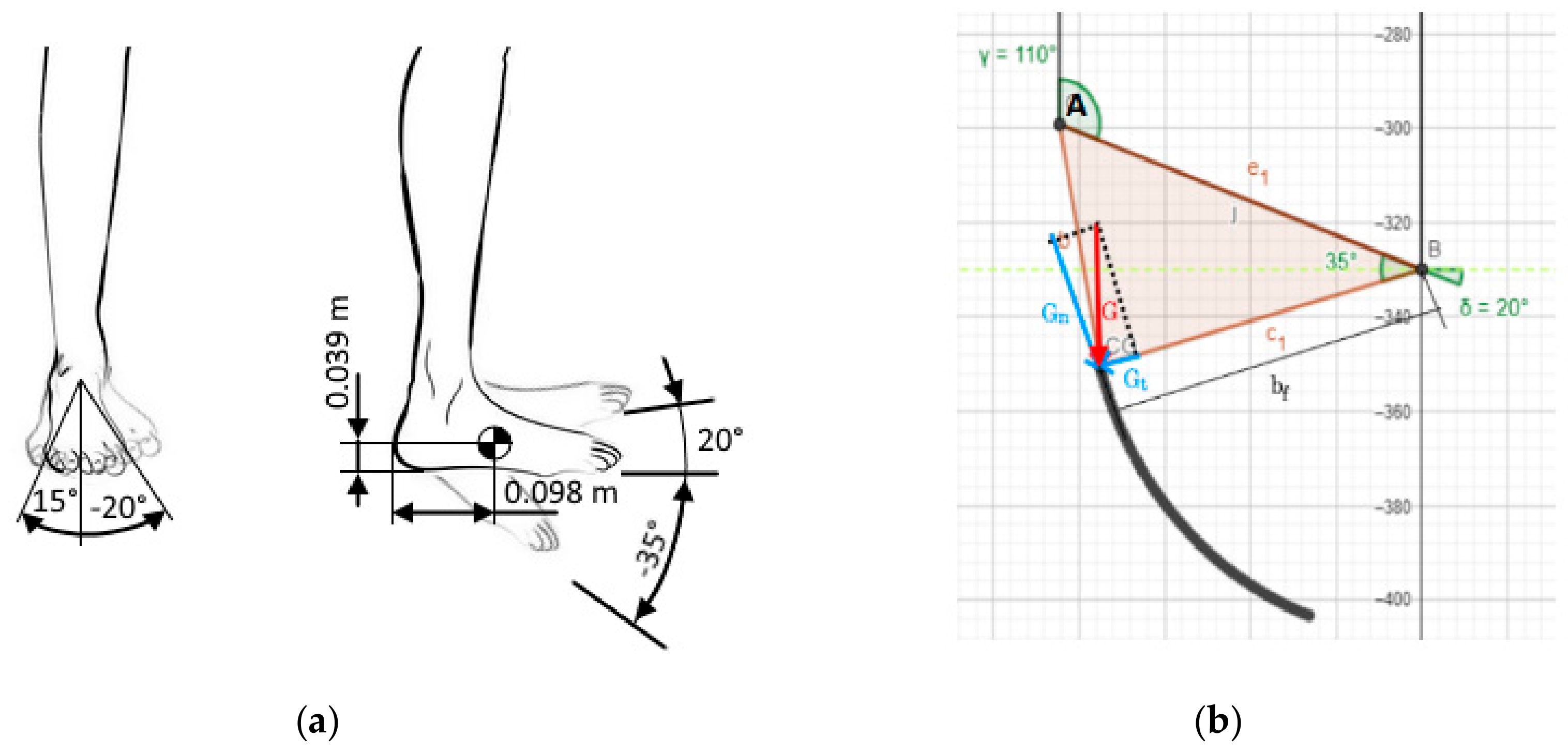
The mechanical subsystem is designed to enable movement only in a predictive fashion; for a correctly executed exercise, a proper attachment to the foot is necessary that lines the bones, muscles, and tendons in an anatomically appropriate way. In order to achieve this goal, biomechanical data were taken into account, namely, it was hypothesized that the exerciser is used by a person 1.65 m tall with a mass of 50 kg; this gives a weight of the foot of 7.13 N and a position of the center of gravity (CG) by the following coordinates in relationship to the heel: 0.098 m horizontally and 0.039 m vertically (
Figure 1a). The range of movement of the foot in relationship to the transverse plane allowed by the exerciser is −35°; 20° for the plantar flexion/dorsiflexion; −20° and 15° for inversion and eversion, respectively. Given these data and using the geometrical relationship between the foot CG and the designed mechanism (
Figure 1b), the result is a maximum necessary moment of 0.37 Nm for the first DOF, and 0.27 Nm for the latter.
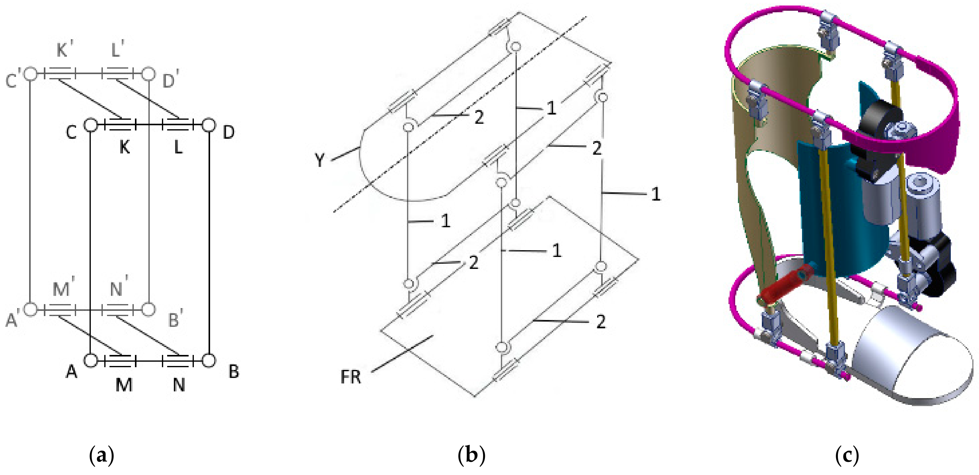
The employed mechanism is a spatially stacked version of the well-known four bar linkage. Its main purpose is to provide a way of simultaneously actuating both degrees of freedom; 4 four-bar linkages are connected to form a parallelepiped, each vertex being formed out of two rotational joints, their axes perpendicular to each other and parallel to the other 3 sister joints axes (
Figure 2a). The placement of a motor in one of the joints is trivial for actuating one DOF, but the second actuated DOF (
Figure 2b dotted line) raises additional issues, as the linkage has to be connected to a fixed reference; if directly connected, the whole DOF is pinned. The designed solution was to incorporate in the power train an universal joint coupled to a sliding shaft with parallel splines; this allows the necessary tilt angle as well as accounting for the radial displacement. Due to the fact that the mobile part of the exerciser has considerable mass, additional support mechanism is employed: two gas cylinders, their ends connected by spherical joints add stability to the system (drawn with red on
Figure 2c).
Referring to the aforementioned figure, the immovable part (drawn with blue) is attached to the leg by Velcro straps, which are not pictured, as to not overload the schematic. The foot is resting on a specifically designated platform. The design is modular, so that the footrest is easily changeable to accommodate various feet sizes by removing and reinserting the bottom U-shape shaft (drawn in magenta on
Figure 2c). The normal operation of the exerciser presumed oscillatory movement, therefore the design does incorporate only plain bearings; the friction is dealt by using polytetrafluoroethylene bushing, the low speed nature of the real life use case scenario allowing sufficient time for cooling. The CAD model was designed using SolidWorks software package published by Dassault Systèmes.
3.2. Electronics Subsystem
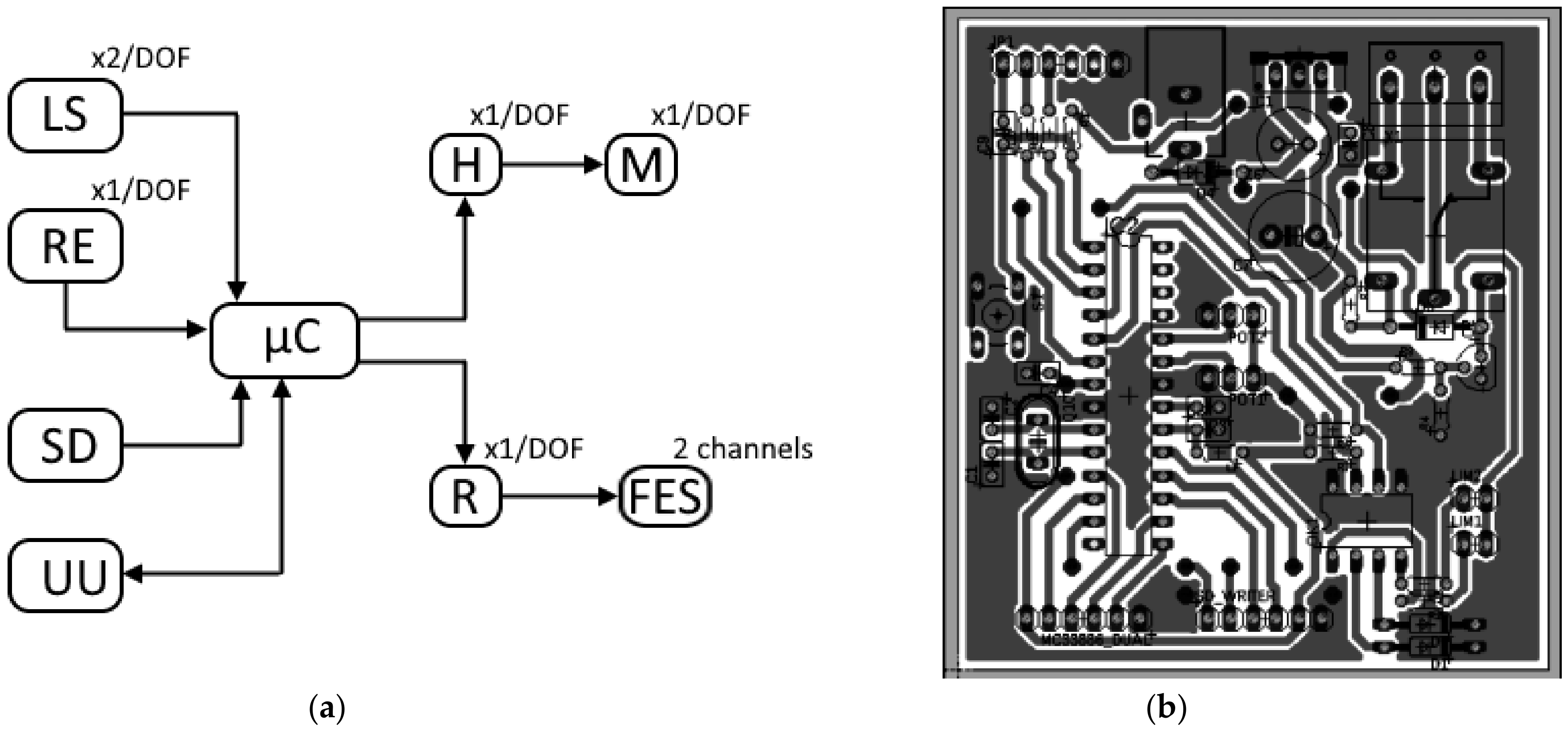
The electronics subsystem is built around an ATmega328-P microcontroller (refer to
Figure 3a) that commands the actuation of the mechanical subsystem with two electrical motors, each powered by an H-bridge. Each electrical motor is encapsulated with a 210:1 gear ratio transmission, capable of delivering up to 3 Nm of torque, which is well above the computed necessary. The H-bridge is compatible with PWM signals and also provides a quick response disable input. The angular positioning of each DOF is monitored with a resistive absolute encoder that provides an accuracy of ±0.3°. For additional safety, each DOF has 2 normally-closed limit switches, each of them controlling a normally-open relay in such a manner that if one of the limit switches is tripped, or the power to the switches is somehow interrupted (rusted connection, torn wire, etc.) only one direction is stopped; therefore, recovery of the system is still possible in normal operation and a high standard of safety is employed. Each faulty state is signaled to the microcontroller galvanically insulated through an optocoupler that drives the first interrupt pin to which an interrupt routine is attached.
An SD-card module is included which allows for upload of different exercises; the file is a simple text string, each row containing one command that contain the desired position and maximum allowable speed for each motor as well as the necessary commands for the start/stop of FES system. The FES system used by the exerciser is a commercially available 2-channel device interfaced with by relay; therefore, the pulse length, frequency and amplitude of the stimulation is manually dialed in before commencing the exercise, the microcontroller merely starts or stops the device. The placement for the FES electrodes on the skin is covered by the device user manual and might be performed either by a physical therapist or the patient after receiving a precursory instruction. The exerciser’s main electrical circuit was implemented on a single layer printed circuit board (PCB), pictured in
Figure 3b, using EAGLE (published by Autodesk); it is worth noting that this PCB is not entirely necessary if an Arduino board were to be used. Furthermore, for programming as well as testing purposes, communication over a USB to UART converter is employed.
3.3. Control Subsystem
ATmega328-P microcontroller is a popular microchip with the Arduino device family; therefore, the Arduino IDE was used in code design for its easy-to-use libraries. The motors were controlled using a PID algorithm implementation which reads the signal from the resistive absolute encoders through the microcontroller integrated 10-bit ADC and compares it to the target position provided by the exercise file that resides on the SD-card. The output from the PID controller is a PWM value that is proportionally to the motors speed; it is worth noting that if the value is negative, which correlate with the rotation in the opposite direction, a simple function remove the sign and invert the signal before further processing. The sign triggers a flag that signalize the H-bridge which combination is active, so that the motor can easily turn. In order to limit the speed in a safe range, the PWM value is capped before writing it in the appropriate PWM register with the value specified in the exercise file. The overall safely usage of the exerciser is ensured by the hardwired limiters described in the precedent subchapter, but as a first line of secure operation there are also software-defined limits which maintain a physiological range of motion.
Another mode of operation is by permanent connection via an USB-UART converter. At this stage a simple graphical user interface was designed in Matlab GUIDE, but further development was halted until prototype completion. If a limit switch is activated, an interrupt routine drives the H-bridge low and throws an error; putting the H-bridge on hold is redundant, as the wiring, described in subchapter 3.2, already cuts the power to the motor; as a result, the system has triple redundancy for emergency stop: software defined limits, external interrupt routine and hardware-defined limits, so even in case of end-user interference with the safety checks, it is reasonable to expect that at least one remains active.
4. Conclusions
This paper presented the design stages of a hybrid 2-DOF lower limb exerciser; although the work done so far is enough to grant the manufacture of a first prototype, several issues were identified and are taken into account for a future iteration. First of all, it is necessary to make sure that the exerciser is capable of serving a broader demographic; even though the selected motors have a 8-fold power margin, there was no rigorous calculation of the needed torque in order to cover at least the 95th percentile for height and mass of the population. A useful improvement would be the addition of strain gauges; not only would the operational safety increase (if an anomalous strain is detected, the exerciser stops and avoid potential injury), but it would also enable active and passive mode usage. Therefore, a patient might continue to use the exerciser for different stages of their rehabilitation; in the beginning, when the musculature is still weak, the system might work in a passive mode to maintain articular mobility; in the later stages, when the musculature begin to strengthen, the exerciser might switch to an active mode, opposing the movement with a certain force controlled by the strain gauges.
Another design requirement for a future iteration is the simplification of the actuating system; one of the DOF is directly connected to the motor, which makes the actuation very robust. The second DOF is connected with a quite complex transmission which is prone to failure. There are already several design solutions being investigated, but not fully explored at this time. Modern equipment tends to have implemented diverse communication protocols that use the radio spectrum; in this regard, a future development will be the addition of a Bluetooth module that will enable communication with a smartphone app. Another idea worth investigating is implementing Wi-Fi functionality, but this direction must be carefully approached, as connecting a medical device to a computer network might expose the patient to malicious actors over the internet. Another planned improvement is related to multiple exercise selection: in preparation for the prototype, the designed code is capable of reading only one file; a file management system has to be implemented, which will allow multiple exercise files to be loaded on the SD card and chosen by the physical therapist or patient, presumably with a Bluetooth-connected smartphone. As soon as full activity in the Biomechatronics Laboratory is allowed (currently reduced by measures taken to stop the spread of SARS-CoV2), a prototype will be build using the additive manufacturing technologies available; this prototype will be further used for preliminary testing, and, if found satisfactory, pre-clinical testing using healthy volunteers.
Author Contributions
Conceptualization, D.L. and A.I.-A.-D.; methodology, A.I.-A.-D.; software, L.I.V.; validation, A.I.-A.-D.; formal analysis, A.I.-A.-D.; investigation, L.I.V.; resources, L.I.V.; data curation, A.I.-A.-D.; writing—original draft preparation, D.L.; writing—review and editing, D.L.; visualization, A.I.-A.-D.; supervision, A.I.-A.-D.; project administration, A.I.-A.-D. All authors have read and agreed to the published version of the manuscript.
Funding
This research received no external funding.
Conflicts of Interest
The authors declare no conflict of interest.
References
- Farris, R.J.; Quintero, H.A.; Goldfarb, M. Preliminary Evaluation of a Powered Lower Limb Orthosis to Aid Walking in Paraplegic Individuals. IEEE Trans. Neural Syst. Rehabil. Eng. 2011, 19, 652–659. [Google Scholar] [CrossRef] [PubMed]
- Quintero, H.A.; Farris, R.J.; Hartigan, C.; Clesson, I.; Goldfarb, M. A Powered Lower Limb Orthosis for Providing Legged Mobility in Paraplegic Individuals. Top. Spinal Cord Inj. Rehabil. 2011, 17, 25–33. [Google Scholar] [CrossRef] [PubMed]
- Vlasin, L.I. Design of a Hybrid Rehabilitation System Composed from an Orthosis and a Functional Electrical Stimulation Unit; Technical University of Cluj-Napoca: Cluj-Napoca, Romania, 2020. [Google Scholar]
- Stein, R.B. Assembly for Functional Electrical Stimulation during Movement. U.S. Patent No. 5,643,332, 1 July 1997. [Google Scholar]
- Gil, J.; Sanchez-Villamanan, M.; Gomez, J.; Ortiz, A.; Pons, J.; Moreno, J.; Del-Ama, A. Design and Implementation of a Novel Semi-Active Hybrid Unilateral Stance Control Knee Ankle Foot Orthosis. In Proceedings of the 2018 IEEE/RSJ International Conference on Intelligent Robots and Systems (IROS), Madrid, Spain, 1–5 October 2018; pp. 5163–5168. [Google Scholar]
- Liu, Q.; Wang, C.; Long, J.J.; Sun, T.; Duan, L.; Zhang, X.; Zhang, B.; Shen, Y.; Shang, W.; Lin, Z.; et al. Development of a New Robotic Ankle Rehabilitation Platform for Hemiplegic Patients after Stroke. J. Health Eng. 2018, 2018, 1–12. [Google Scholar] [CrossRef] [PubMed]
- Akdoğan, E.; Adli, M.A. The design and control of a therapeutic exercise robot for lower limb rehabilitation: Physiotherabot. Mechatronics 2011, 21, 509–522. [Google Scholar] [CrossRef]
- Aroche, O.N.; Meyer, P.-J.; Tu, S.; Packard, A.; Arcak, M. Robust Control of the Sit-to-Stand Movement for a Powered Lower Limb Orthosis. IEEE Trans. Control. Syst. Technol. 2019, 28, 2390–2403. [Google Scholar] [CrossRef]
- Sunada, T.; Obinata, G.; Pei, Y. Active Lower Limb Orthosis with One Degree of Freedom for Paraplegia. In Proceedings of the 16th International Conference on Informatics in Control, Automation and Robotics, Prague, Czech Republic, 29–31 July 2019; SciTePress: Setúbal, Portugal, 2019; pp. 504–509. [Google Scholar] [CrossRef]
- Roula, N.; Chemori, A.; Rizk, R.; Zaatar, Y. On Control Design for a Lower Limb Orthosis: A Comparative Study in Different Operating Conditions. Adv. Mech. Mach. Sci. 2018, 58, 81–97. [Google Scholar] [CrossRef]
| Publisher’s Note: MDPI stays neutral with regard to jurisdictional claims in published maps and institutional affiliations. |
© 2020 by the authors. Licensee MDPI, Basel, Switzerland. This article is an open access article distributed under the terms and conditions of the Creative Commons Attribution (CC BY) license (http://creativecommons.org/licenses/by/4.0/).

