1. Introduction
Understanding the neuronal ensemble as well as their connectivity through recondite synapses in the brain or even in a limited regain of the nervous system is one of the most challenging topics in researching fields over several past decades. In this regard, due to the development of microstructure technologies in the last 30 years, significant advances have been observed in tools and methods to measure the electrical activities of excitable cells (neurons and cardio-myocytes) both in vitro and in vivo, which gives the necessary knowledge to understand the characteristics and function of the excitable cells of the brain and heart.
To date, the in vitro study of neural network electrical activity under physiological or pathological conditions largely relies on multi-electrode arrays technology. Due to the uniform distribution of the arrays and their non-invasive properties, this technology allows long-term studies at the neural network level to overcome the problems of conventional extrinsic electrophysiological techniques such as patch clamps. Indeed, the technology allows a precise understanding of the excitable network, drug screening, and neural prosthesis studies. The working principle of multi-electrode arrays is excitable cells generate the action potential by ion exchange through their membrane and the electrodes of MEAs are able to record the consequent fluctuations in the electrical field of the extracellular milieu of the cells. This non-invasive communication between the electrode and cell enables us to perform stimulation in addition to long-term recordings from the network [
1,
2].
For electrical excitation and recording, electrodes with high selectivity, low impedance, high density, and multidimensional geometry are preferred to stimulate neurons and to achieve a high signal-to-noise ratio (SNR). During recording and stimulation, the impedance of the electrodes serves as the bridge of the current transducer, and less power and less background noise resulted from the electrodes with lower impedance. To achieve high selective electrodes, the electrodes should be as small as possible which results in electrodes with higher impedance. To consider this trade-off, we must study a combination of all the main aspects, including the design of the geometry, the material, and the manufacturing techniques [
2,
3].
The multi-electrode arrays could be fabricated in two ways: mini MEA fabrication, and printed circuit board (PCB) with CMOS technology as the most expensive one [
4,
5]. Both methods involve complicated processes that lead to high-cost electrodes. For most laboratories conducting multiple studies, both commercially available and fabricated MEAs are too costly [
3]. In this work, we are focusing on fabricating low-cost multi-electrode array chips using feasible material and microfabrication methods that are cost-effective for several laboratories. The plane microelectrodes were fabricated with conventional microfabrication processes including photolithography, metal sputtering, deposition of insulators, and etching. In the following sections, the design and fabrication process of the low-cost high-density MEA are described. That is followed by the presentation of good cell adhesion and bio-compatibility of the manufactured MEA which is going to be evaluated by neural cells, obtained from rat cortices.
2. Design of the Planar Microelectrodes Array
The number of electrodes intended in multi-electrode arrays is the first parameter to be considered in its design which can vary between 16 to 512 [
6]. Greater numbers of electrodes may lead to much more accurate recording plus more targeted manipulation of each cell in the network. In fact, by increasing the electrode figures, most regions of a single neuron comprising the dendrite, soma, and axon are accessible for either recording or stimulating, which represent a perfect map of the neuronal ensemble as a result. Besides, more simultaneous recordings reduce the noise level of the system due to the differential relationship of the electrodes with each other. Additionally, improving the quality of the signals requires enlarged dimensions of the electrodes, which reduces the resolution of the received signals in terms of the position of the cells and their components. Therefore, the size of the electrodes in such a way to achieve the desired selectivity is another criterion in the MEA designing. In recent years, depending on the types of application, the diameter of the electrodes is usually considered to be 10 to 50 microns [
4,
6,
7].
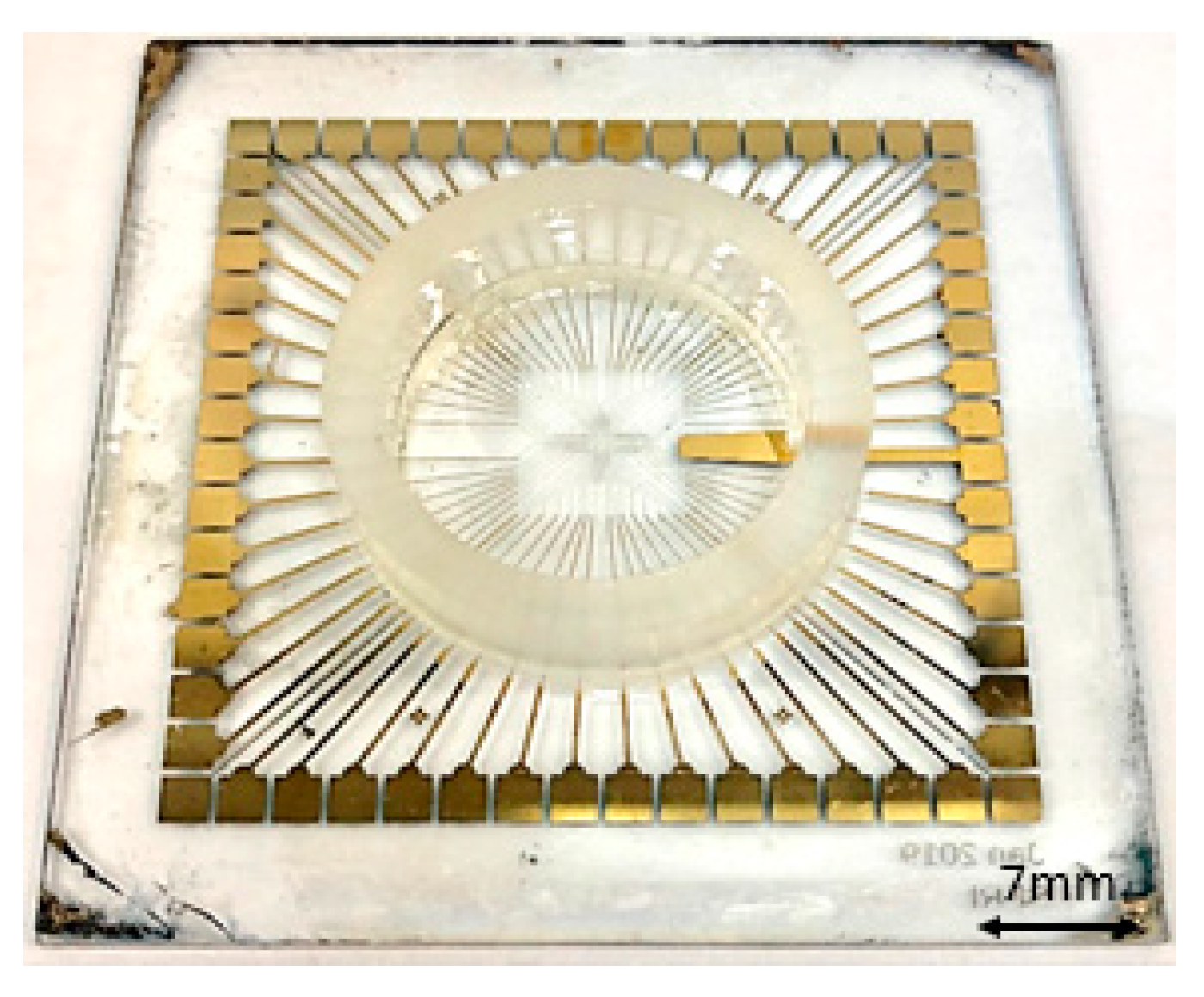
Subsequently, in this work, the number of electrodes is chosen 60, on a square-shaped glass substrate with a side length of 5 cm and 1 mm thickness. As a standard size for the MEA chips, the diameter of electrodes is considered 30 mm and the contact pads are square with a side length of 200 mm. On this substrate, we place a glass ring with an outer diameter of 2.4 cm, an inner diameter of 1.9 cm, and a height of 6 mm to culture the cells within.
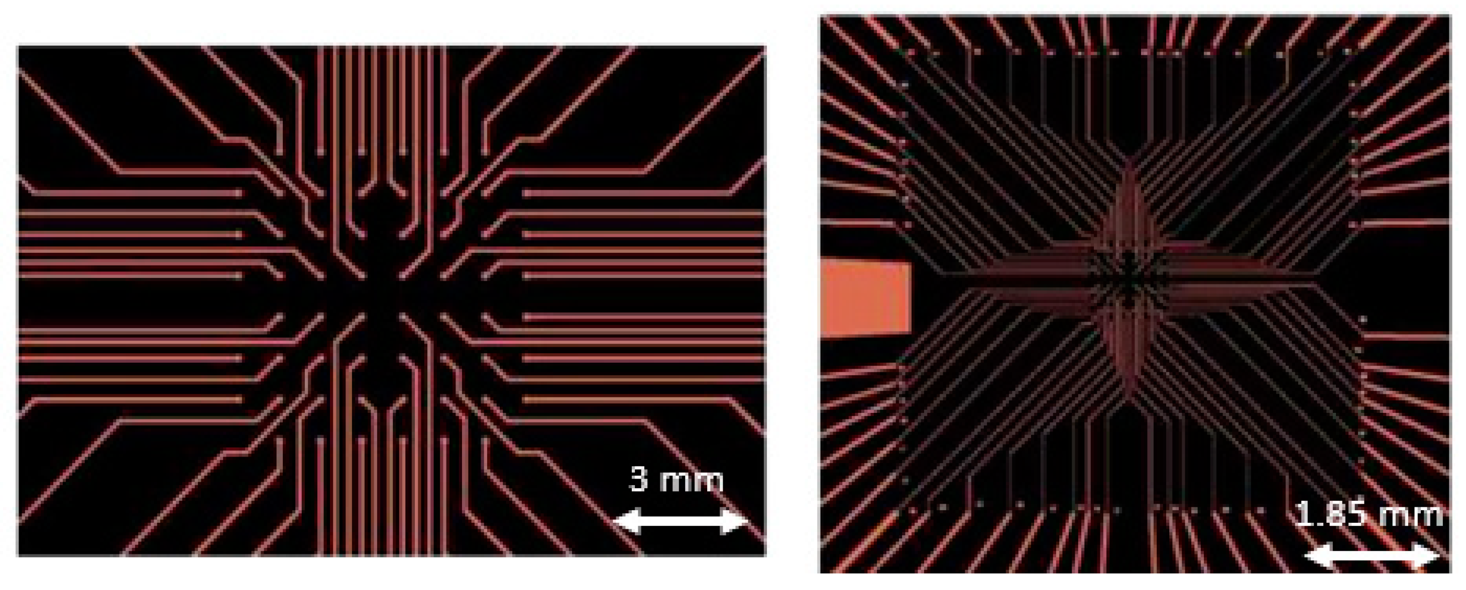
The proposed pattern of 60 electrodes for a planar multi-electrode array was designed using the advanced design system (ADS) and Layout editor softwares, shown in
Figure 1. Then, we create a chrome mask for our photolithography process.
3. Fabrication of Planar Multi-Electrode Array
3.1. Fabrication Consideration
To manufacture the designed MEA, careful selection was made for the materials of the substrate, conductor, insulator. In fact, in the fabrication process of multi-electrode arrays, several substantial criteria must be considered: First of all, all substances that come into contact with the cellular system must be biocompatible, optically transparent, rigid, and durable to cell culture conditions. Secondly, since the amplitude of the action potential (AP) signals is relatively small, the parasitic impedance in the action potential signal sensing site and path should be as low as possible. Thirdly, the insulation layer of the multi-electrode array must have a high impedance so that the action potential signal is not significantly attenuated. Finally, the measurement system should not have a negative effect on the physicochemical environment [
6,
8].
During recording extracellular signals, it is best to keep the underside of the electrode transparent so that the system can be viewed under a microscope for further processes. In this work, we have used silica (glass) substrates as a very low-cost substrate in comparison to other substrates often chosen like quartz [
9,
10] or Si wafer [
11,
12].
The material has a great effect on the electrical properties measured from the cells. Also, the adhesion of the material must be considered in the fabrication process of electrodes. In most related scientific articles, electrode selection is divided into two groups of metals and conductive polymers [
5]. Polymers are generally used when a flexible electrode is needed to record living organisms. Such electrodes are usually more difficult to fabricate than metal electrodes. However, for extracellular recording, the use of metals is appropriate compared to polymers due to their strength and reusability. Common metals used in fabrication include gold, platinum and titanium. These metals are biocompatible and resistant to corrosion [
6,
8,
13,
14,
15].
After studying the adhesion, conductivity and surface strength of the three available options of gold, platinum and titanium, we used gold because of its longevity. In other words, based on the durability and stability of the electrodes over time which has great importance, gold was chosen in this study. The impedance of platinum electrodes is low, but gold is more stable than platinum and titanium [
15,
16]. Additionally, gold has other properties that make it suitable for coating medical instruments. These properties include high flexibility, non-oxidation, cell compatibility, high density (which makes it resistant to X-rays), high conductivity, and its reliable bonding to other metals.
However, because gold does not adhere well to glass, a buffer layer such as nickel, titanium or chromium should be used as an adhesion interface between gold and glass [
4,
8,
14]. In this work, we have chosen a thin layer of titanium as the buffer layer metal.
Another important point in the fabrication of multi-electrode arrays is the use of efficient electrical insulators to prevent voltage leakage as much as possible. Besides, the lack of insulation causes interference between the channels, which is problematic for recording. Moreover, the insulation layer must have a low dielectric constant or a high thickness to reduce the parasitic capacitors formed between the cell culture medium and the electrode. Also, the insulating material must have an inert surface so that it does not react with the ions in the aqueous solution [
4].
In this work, we have chosen organic photoresist SU-8 as the insulator material. SU-8 has several applications in the deposition process such as the patterning of electrodes and their insulation. Also, due to its biocompatibility, it can be used directly as an insulating layer. This material has a relatively long life and its coating and etching methods are very simple to compare to other insulators like silicon nitride or dioxide materials [
8].
Based on the fabrication considerations declared in this section and based on the materials chosen to manufacture the planar MEA, the fabrication process is described in detail in the following section. All materials and processes are readily available and even cost-effective in comparison to other materials used in the microfabrication process.
3.2. Fabrication Process
Figure 2 shows a step-by-step process for the fabrication of the proposed gold/titanium multi-electrode array chip. These steps include cleaning and preparing the sample surface, deposition of the buffer metal (titanium), deposition of the gold layer, adding the photoresist to the sample, and photolithography to create the desired design on the sample. Acid etching of metal layers in specific areas, adding an insulating layer to isolate the channels, and insulating the connection paths and the surface are the next steps shown in
Figure 2g–k.
Before deposition of metal layers with the dc-sputtering coating technique, the substrate must be cleaned with acetone, high-purity isopropyl alcohol and Piranha solution to remove a high percentage of contaminants. Since the substrate used in this study is glass, in order to degas it and improve the quality of the deposited layers, we must heat the sample in a high-temperature furnace before the sputtering process. Also, since the evaporation of water from the surface of the substrate is an important factor in determining the geometric structure of the coating layers, the temperature of the substrate must be up to about 200 °C during deposition [
17].
The ratio of the thickness of the gold layer to the buffer titanium layer should be such that it does not change the impedance and conductivity of the gold electrodes and at the same time causes the proper adhesion of the gold layer to the substrate. After sputtering of 120 nm titanium in vacuum pressure of 2 × 10⁻⁵ Torr, we could continue with the deposition of the gold layer. Afterward, we deposited the 80 nm layer of gold at a pressure of 58 mTorr on the Titanium coated glass substrate. This step was followed by a plasma treatment step using oxygen gas to activate the sample surface.
After the standard photolithography process, using S1813 as the positive photoresist, and Aqua regia and dilute hydrofluoric acid as gold and titanium etchant respectively, the sample was ready for the deposition of the insulation layer. Except for the contact pads and the ground connection electrode, all other parts of the chip should be insulated. A thin biocompatible insulation layer (Microchem SU-8 photoresist) was deposited on the sample. By heating the chip, it becomes very rigid and can be used for signal recording for several months.
The final step is locating the glass ring on the sample; the adhesion should resist to heat and laboratory operations. The area inside surrounded by the ring is a place for culturing cells. After adhering the ring to the substrate, the outer wall of the ring was covered by a thin layer of SU-8 as a protective insulation material to ensure the insulation and biocompatibility of the sample surface.
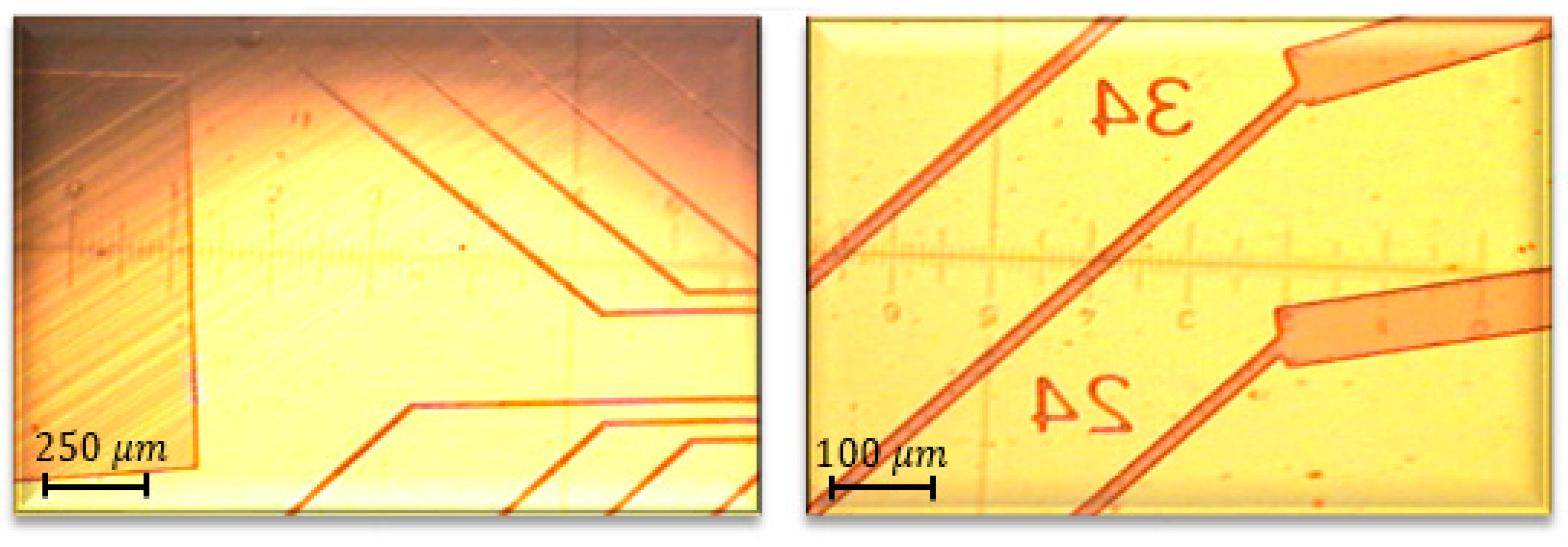
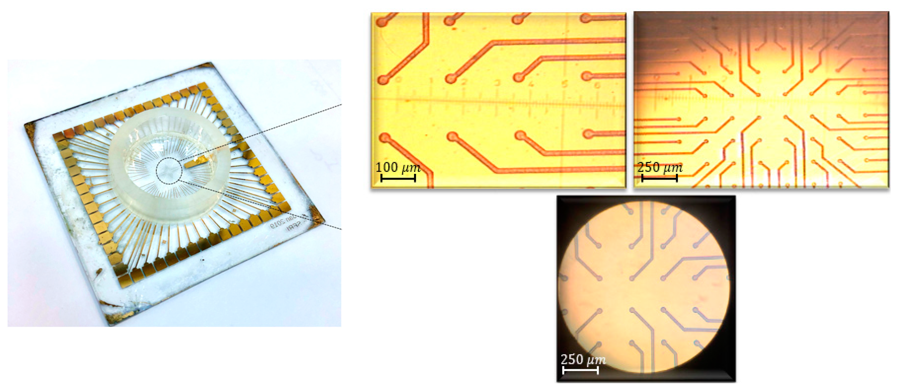
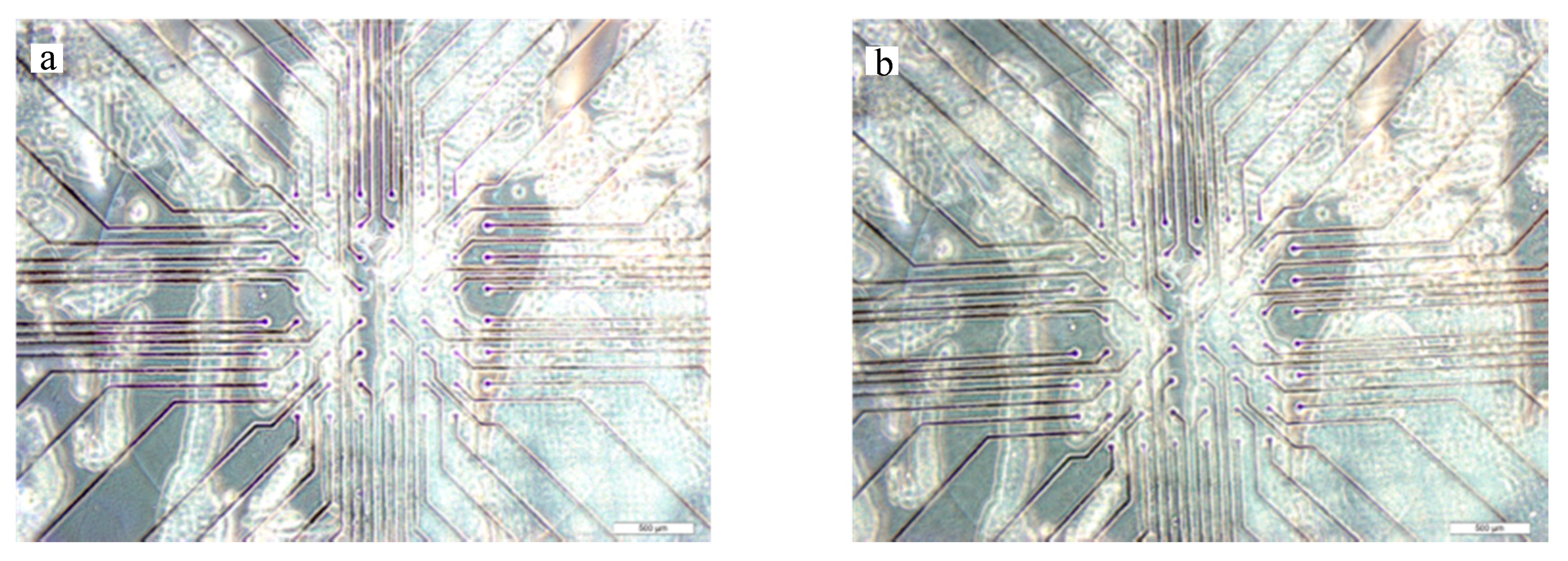
Figure 3,
Figure 4 and
Figure 5 show a final multi-electrode array chip, and the microscopic view of electrodes and connection lines structures, respectively.
4. MEA Preparation Prior to Neural Cell Culture
The manufactured MEA was washed with Terg-a-zyme® detergent (Z273287; Sigma-Aldrich, Darmstadt, Germany) on a vertical shaker for 1 h at room temperature. Afterward, the chip was sterilized inside 70% ethanol for 15 min and then left to dry under a laminar flow cabinet. For the perfect attachment to be accomplished between neurons and glass, the MEA surface ought to be treated with appropriate proteins prior to cell seeding. Therefore, sterile MEA was coated by Poly-L-ornithine (PLO, P4957; Sigma-Aldrich, Darmstadt, Germany) plus Laminin (L2020, Sigma-Aldrich, Darmstadt, Germany) in 37 °C for one and three hours, respectively.
4.1. Neural Cell Isolation from Rat Cortices
Cultured neurons on MEA were isolated from rat cerebral cortex between E16-18 gestational stage. The isolation process was executed according to the previously described protocol with several modifications [
18]. In brief, a pregnant rat was euthanized in compliance with institutional guidelines. In the next step, the animal’s abdominal skin and peritoneum were cut, seperately, to expose the abdominal cavity. Then, the embryo containing uterus was transferred into ice-cold dissection buffer comprised of: Hank’s Balanced Salt Solution (HBSS, 14025-050; Gibco, Gaithersburg, MD, USA) + 20 mM Glucose (G7021; Sigma-Aldrich, Darmstadt, Germany) + 1% GlutaMAX (35050-038; Gibco, Gaithersburg, MD, USA) + 100 U/mL Penicillin-Streptomycin + 50 mg/mL Gentamycin (15750-060; Gibco, Gaithersburg, MD, USA). All embryos were decapitated immediately via sharp scissors. Thereafter, in order to expose the cortical lobes, the head skin as well as the skull tissue were removed using micro scissors. Eventually, the superficial layer of the cortices was dissociated from the whole brain via small short curved forceps and was immersed inside the Phosphate-buffer saline (PBS-, 10010-031; Gibco, Gaithersburg, MD, USA) supplemented with: 20 mM Glucose (G7021; Sigma-Aldrich, Darmstadt, Germany) + 1% GlutaMAX (35050-038; Gibco, Gaithersburg, MD, USA) + 100 U/mL Penicillin-Streptomycin + 50 mg/mL Gentamycin (15750-060; Gibco, Gaithersburg, MD, USA). In the following, the covering meninge was removed accurately to prevent blood cell contamination and then the cortical tissue was dissected into small pieces. In the next step, neuronal cells were isolated from the small tissue pieces by enzymatic treatment, consuming 0.25% Trypsin-EDTA (15400-054; Gibco, Gaithersburg, MD, USA) for 20 min at 37 °C.
4.2. Neural cell Culture on MEA
The isolated neurons were nourished by NeurobasalTM Medium (21103-049; Gibco, Gaithersburg, United States) supplemented with 2% B27 (17504-044; Gibco, Gaithersburg, MD, USA) + 1% horse serum (H1138; Sigma-Aldrich, Darmstadt, Germany) + 1% GlutaMAX (35050-038; Gibco, Gaithersburg, MD, USA) + 100 U/mL Penicillin-Streptomycin + 20 mM Glucose (G7021; Sigma-Aldrich, Darmstadt, Germany). The medium was exchanged completely after 24 h of cell seeding and then in a half-half manner every other day.
5. Results
The MEA preserved a robust structure during pre-culture treatments. The preliminary evaluation of the manufactured MEA were performed so all the features were compared to the original standard MEA chip purchased from the Multichannel system company. The MEA was washed perfectly in order to remove cell debris as well as contaminates from the surface. Also, it was sterilized to prevent further cell contamination before cell culture. During the washing and sterilizing process, we did not observe detachment of the ring from the surface or any fracture on the whole product. Moreover, the arrays of the electrode seemed to retain intact after the washing and sterilization under the microscope (
Figure 6). The higher temperature of the incubator (37 °C) did not affect the ring adhesion robustness during the coating process.
The biocompatibility of the MEA is going to be addressed. To evaluate the biocompatibility of the MEA, we isolated neural cells from rat cortices. After neural isolation, around 400 × 103 cells, suspended in 1 mL medium, were seeded on the MEA. Cell attachment to the surface will be assessed visually via light microscopy and the percentage of the cell viability will be determined by MTS assay in the next step of the study.
6. Conclusions
In this paper, we have designed and manufactured a low-cost planar gold/titanium multi-electrode array chip on a silica substrate with 60 electrodes with 30 mm diameter and the biocompatible insulation layer of SU-8 using standard microfabrication methods. The choice of substrate, method, and materials is based on resulting a cost-effective product. In other words, glass because of its low cost, gold because of its stability and high biocompatibility, and SU-8 because of the simplicity of the manufacturing process as well as its biocompatibility were chosen. The multi-electrode array was prepared using these materials and the standard non-expensive microfabrication method. In this study, the biocompatibility of the manufactured MEA is to be assessed for long time by neural primary culture. The aim is to monitor the cell’s attachment to the glass surface as well as the ability of the neural cells to freely extend their dendrite and axons in a natural timeline, via light microscopy. Moreover, the accurate percentage of cell death will be stochastically assessed for long periods of time by MTS assay in the next step to illustrate the influence of the consuming materials on neural cell survival.


 ,
, 