Proceeding Paper

Closed Irreversible Cycles Analysis Based on Finite Physical Dimensions Thermodynamics †

1
Mechanical Engineering Faculty, “Gheorghe ASACHI” Technical University of Iasi, 700050 Iasi, Romania
2
Laboratoire d’Énergétique et de Mécanique Théorique et Appliquée, UMR 7563, Université de Lorraine, 54505 Vandoeuvre-lès-Nancy, France
*
Author to whom correspondence should be addressed.
Presented at the First World Energies Forum, 14 September–05 October 2020; Available online: https://wef.sciforum.net/.
Proceedings 2020, 58(1), 37; https://doi.org/10.3390/WEF-06905
Published: 11 September 2020
(This article belongs to the Proceedings of The First World Energies Forum—Current and Future Energy Issues)

Abstract

:
The paper develops generalizing entropic approaches of irreversible closed cycles. The mathematical models of the irreversible engines (basic, with internal regeneration of the heat, cogeneration units) and of the refrigeration cycles were applied to four possible operating irreversible trigeneration cycles. The models involve the reference entropy, the number of internal irreversibility, the thermal conductance inventory, the proper temperatures of external heat reservoirs unifying the first law of thermodynamics and the linear heat transfer law, the mean log temperature differences, and four possible operational constraints, i.e., constant heat input, constant power, constant energy efficiency and constant reference entropy. The reference entropy is always the entropy variation rate of the working fluid during the reversible heat input process. The amount of internal irreversibility allows the evaluation of the heat output via the ratio of overall internal irreversible entropy generation and the reference entropy. The operational constraints allow the replacement of the reference entropy function of the finite physical dimension parameters, i.e., mean log temperature differences, thermal conductance inventory, and the proper external heat reservoir temperatures. The paper presents initially the number of internal irreversibility and the energy efficiency equations for engine and refrigeration cycles. At the limit, i.e., endoreversibility, we can re-obtain the endoreversible energy efficiency equation. The second part develops the influences between the imposed operational constraint and the finite physical dimensions parameters for the basic irreversible cycle. The third part is applying the mathematical models to four possible standalone trigeneration cycles. It was assumed that there are the required consumers of the all useful heat delivered by the trigeneration system. The design of trigeneration system must know the ratio of refrigeration rate to power, e.g., engine shaft power or useful power delivered directly to power consumers. The final discussions and conclusions emphasize the novelties and the complexity of interconnected irreversible trigeneration systems design/optimization.

1. Introduction

The energy systems, single or combined power and heat and refrigeration ones, are critical issues since the energy needs rise every year. The design of standalone energy systems is focused only on the energy client’s requirements and it is pursuing the partial optimized energy efficiency. This design ignores, however, the overall energy connections and thus the impacts on the other energy systems and energy clients and on the environment. The management of energy systems originates new restrictive operational constraints such as variable energy needs depending on the environmental temperatures or on the time. The electrical power systems are interconnected through the national and international electricity grids which can so safely assure the variable energy needs of any client. The variable useful heat and refrigeration asked by specific customers, e.g., building heating and conditioning systems, could be designed through various scenarios considering possible operational constraints with supposed variable shapes. The best energy solutions are obtained for steady state operation. The variable operation generates energy/exergy losses depending on the energy/irreversibility “inertia”. Currently, almost all researches regarding energy systems, i.e., energy/exergy or exergoeconomic analysis, design, optimization, management, are assigned for new particular applications. For instance, ref. [1] presents an advanced exergoeconomic analysis of a waste heat recovery system based on the organic Rankine cycle from the exhaust gases of an internal combustion engine considering different operating conditions; ref. [2] uses an analytical approach to discuss the relationship between the exergy destruction and efficiency by assuming a simple thermodynamic system simulating an internal combustion engine operation; ref. [3] applies the Exergy Cost Theory to a hybrid system based on a 500 kWe solid oxide fuel cell stack and on a vapor-absorption refrigeration system by a model comprising chemical, electrochemical, thermodynamic, and thermoeconomic equations and using the Engineering Equation Solver; ref. [4] performs exergy and exergoeconomic analysis of a novel combined cooling, heating, and power system, which is based on solar thermal biomass gasification, and finds the exergoeconomic costs of multi-products such as electricity, chilled water, heating water, and domestic hot water by using the cost allocation method based on energy level; ref. [5] identified and discussed the thermodynamic and environmental effects of scaling up systems that operate according Rankine cycle with reheating, considering ten scenarios considering different levels of steam pressure; ref. [6] develops energetic and exergetic analyses using operating data for Sabiya, a combined cycle power plant with an advanced triple pressure reheat heat recovery steam generator; ref. [7] proposes a municipal waste-driven tri-generation system through a comprehensively analysis using thorough thermodynamic, thermoeconomic, and thermoenvironmental investigations; ref. [8] is performing the energetic and financial investigation of three different solar-driven trigeneration systems that can be applied in buildings with high energy needs; ref. [9] develops an optimal trigeneration system based on the Pinch Analysis methodology by minimizing cooling, heating, and power requirements, taking into account energy variations in the total site energy system, and involving seven steps; ref. [10] presents the results of analysis of energy and economic efficiency of the hierarchical gas-gas engine, with a note that a trigeneration system was analyzed; ref. [11] discusses the possibilities of integrating the adsorption aggregate with a combined cycle gas turbine and its impact on the operation of all devices and simulations are performed on Sim tech IPSEPro software; ref. [12] considers a performance analysis of a novel small-scale CCHP – (combined cooling heat & power) system where a biogas-fired, 5 kWel externally fired microturbine, an absorption refrigeration system and heat exchangers are integrated for supplying electricity, refrigeration and hot water demanded by Bolivian small dairy farms, the primary energy/exergy rate was used as a performance indicator.
This paper develops generalizing entropic approaches of irreversible closed cycles. The mathematical models of the irreversible engines (basic, with internal regeneration of the heat, cogeneration units) and of the refrigeration cycles were applied to four possible operating irreversible trigeneration cycles. The models involve the reference entropy, the number of internal irreversibility, the thermal conductance inventory, the proper temperatures of external heat reservoirs unifying the first law of thermodynamics and the linear heat transfer law, the mean log temperature differences, and four possible operational constraints, i.e., constant heat input, constant power, constant energy efficiency and constant reference entropy. The reference entropy is always the entropy variation rate of the working fluid during the reversible heat input process. The number of internal irreversibility allows the evaluation of the heat output via the ratio of overall internal irreversible entropy generation and the reference entropy. The operational constraints allow the replacement of the reference entropy function of the finite physical dimension parameters, i.e., mean log temperature differences, thermal conductance inventory, and the proper external heat reservoir temperatures. The paper presents initially the number of internal irreversibility and the energy efficiency equations for engine and refrigeration cycles. At the limit, i.e., endoreversibility, we can re-obtain the endoreversible energy efficiency equation. The second part develops the influences between the imposed operational constraint and the finite physical dimensions parameters for the basic irreversible cycle. The third part is applying the mathematical models to four possible standalone trigeneration cycles. It was assumed that there are the required consumers of the all useful heat delivered by the trigeneration system. The design of trigeneration system must know the ratio of refrigeration rate to power, e.g., engine shaft power or useful power delivered directly to power consumers.

2. The Irreversible Energy Efficiency—The Number of Internal Irreversibility

The energy efficiency of irreversible energy systems is depending on the irreversibility of all the processes defining the energy cycle. The overall irreversibility might be quantified by the number of internal irreversibility [13]. Through this number and the reference entropy they must be connected the thermal energy interactions with external heat reservoirs (heat source and heat sink) for any energy system. They will be demonstrated the equations of the irreversible energy efficiency for basic closed engine cycle, see Figure 1, closed engine cycle with internal regeneration of the heat, see Figure 2, closed cogeneration cycle, see Figure 3, closed refrigeration cycle, see Figure 4.
The reference entropy, Δsq > 0, is always the entropy variation of the working fluid during the cyclic reversible heating through the cyclic heat input. It must be mentioned that the reversible heat input is equalizing the irreversible one, because the extra irreversible entropy generation, caused by friction is corresponding to an equivalent throttling process. The same statement must be used for the cyclic heat output.
Basic closed engine cycle, see Figure 1
  • The reference specific entropy during the cyclic heating
    Δ s q = s 3 r e v s 2 i r r > 0
  • The specific heat input
    q = T m q Δ s q > 0
    where Tmq is the mean thermodynamic temperature of reversible heating process.
  • The specific entropy variation during the cyclic cooling
    Δ s q 0 = s 5 r e v s 4 i r r = ( Δ s q + Δ s 1 2 + Δ s 2 3 + Δ s 3 4 + Δ s 4 1 ) = Δ s q ( 1 + Δ s 1 2 + Δ s 2 3 + Δ s 3 4 + Δ s 4 1 Δ s q ) = Δ s q N i r r < 0
  • The specific heat output
    q 0 = T m q 0 Δ s q 0 = T m q 0 Δ s q N i r r < 0
    where Tmq0 is the mean thermodynamic temperature of reversible cooling process
  • The number of internal irreversibility (Nirr) and the irreversible energy efficiency (EEirr)
    N i r r = 1 + Δ s 1 2 + Δ s 2 3 + Δ s 3 4 + Δ s 4 1 Δ s q > 1
    E E i r r = w q = 1 + q 0 q = 1 + T m q 0 Δ s q 0 T m q Δ s q = 1 T m q 0 T m q N i r r
    where w is the specific useful work. When N i r r 1 respectively Δ s q 0 Δ s q it is re-obtained the energy efficiency of the endoreversible basic closed engine cycle. The number of internal irreversibility might ensure the needed link between the external heat reservoirs parameters (constant or variable) by the intermediary of the internal overall irreversibility.
Closed engine cycle with internal regeneration of the heat, see Figure 2
  • The reference specific entropy during the cyclic heating
    Δ s q = s 4 r e v s 3 i r r > 0
  • The specific heat input
    q = T m q Δ s q > 0
    where Tmq is the mean thermodynamic temperature of reversible heating process.
  • The specific entropy variation during the cyclic cooling
    Δ s q 0 = s 7 r e v s 6 i r r = [ Δ s q + Δ s 1 2 + Δ s 2 3 + Δ s 3 4 + Δ s 4 5 + Δ s 5 6 + Δ s 6 1 + Δ s r e g ( 1 T r e g T r e g * ) ] = Δ s q N i r r < 0
    where Δsreg is the entropy variation during the pre-heating process 2irr–3rev, Treg is the mean thermodynamic temperature of the pre-heating process 2irr–3rev, T*reg is the mean thermodynamic temperature of the pre-cooling process 5irr–6rev.
  • The specific heat output
    q 0 = T m q 0 Δ s q 0 = T m q 0 Δ s q N i r r < 0
    where Tmq0 is the mean thermodynamic temperature of reversible cooling process
  • The number of internal irreversibility (Nirr) and the irreversible energy efficiency (EEirr)
    N i r r = 1 + Δ s 1 2 + Δ s 2 3 + Δ s 3 4 + Δ s 4 5 + Δ s 5 6 + Δ s 6 1 + Δ s r e g ( 1 T r e g T r e g * ) Δ s q > 1
    E E i r r = w q = 1 + q 0 q = 1 + T m q 0 Δ s q 0 T m q Δ s q = 1 T m q 0 T m q N i r r
    where w is the specific useful work. When N i r r 1 . respectively, Δ s q 0 Δ s q , T r e g = T r e g * , it is re-obtained the energy efficiency of the endoreversible closed engine cycle with internal regeneration of the heat. The number of internal irreversibility might ensure the needed link between the external heat reservoirs parameters (constant or variable) by the intermediary of the internal overall irreversibility.
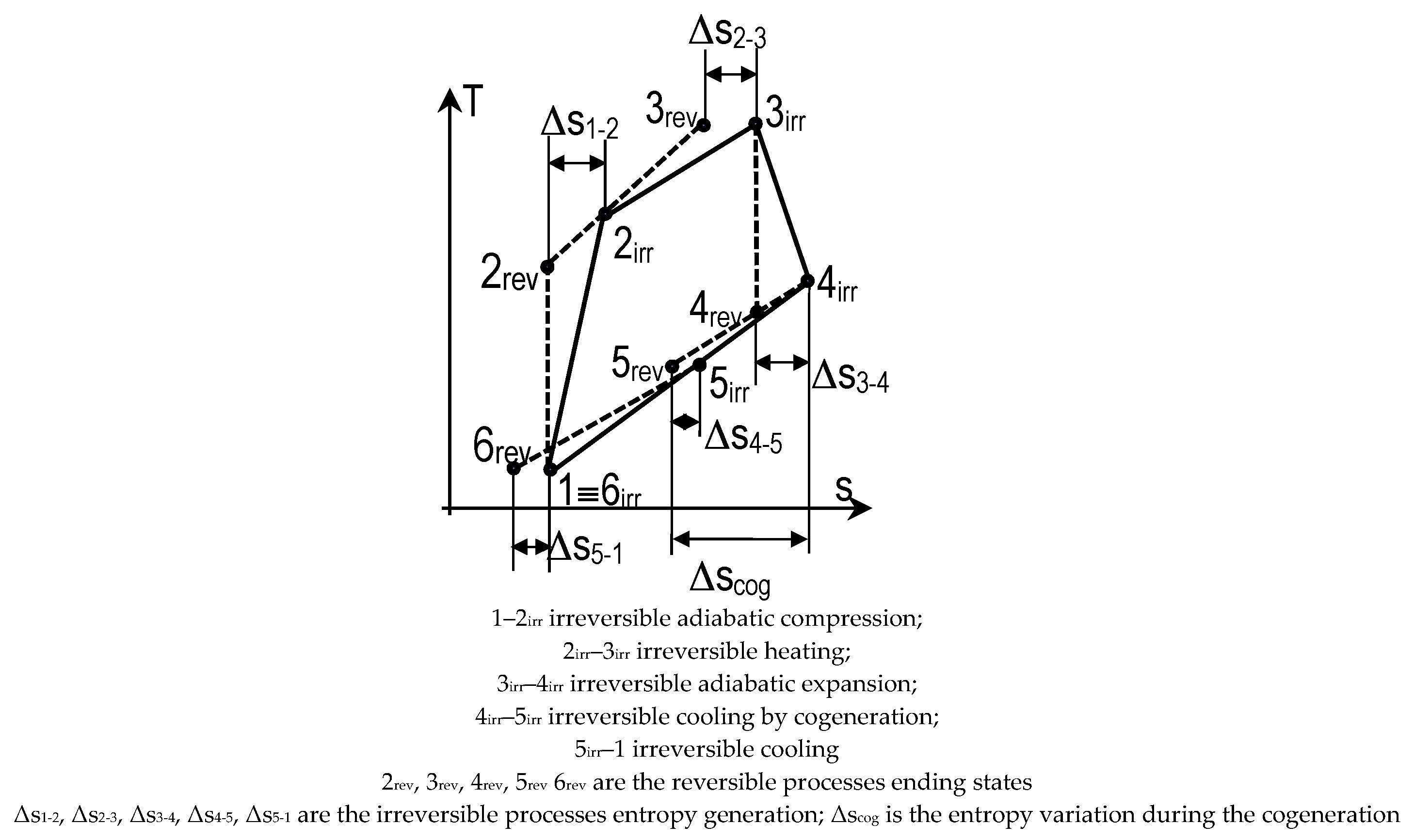
Closed cogeneratione cycle, see Figure 3
  • The reference specific entropy during the cyclic heating
    Δ s q = s 3 r e v s 2 i r r > 0
  • The specific heat input
    q = T m q Δ s q > 0
    where Tmq is the mean thermodynamic temperature of reversible heating process.
  • The specific entropy variation during the cyclic cooling
    Δ s q 0 = s 5 i r r s 6 r e v = [ Δ s q + Δ s 1 2 + Δ s 2 3 + Δ s 3 4 + Δ s 4 5 + Δ s 5 1 + Δ s c o g ] = Δ s q N i r r , c o g < 0
    where Δscog = s5revs4irr < 0 is the entropy variation during the cogeneration (cooling process) 4irr–5rev.
  • The number of internal irreversibility (Nirr,cog)
    N i r r , c o g = ( 1 + Δ s 1 2 + Δ s 2 3 + Δ s 3 4 + Δ s 4 5 + Δ s 5 1 Δ s q ) | Δ s c o g | Δ s q = N i r r b a s i c e n g i n e | Δ s c o g | Δ s q < 1
  • The specific heat output
    q 0 = T m q 0 Δ s q 0 = T m q 0 Δ s q N i r r , c o g < 0
    where Tmq0 is the mean thermodynamic temperature of reversible cooling process.
  • The specific useful heat by cogeneration (qcog) and the irreversible useful power (w)
    q c o g = T c o g ( s 5 r e v s 4 i r r ) = T c o g Δ s c o g < 0
    w = f i r s t l a w q + ( q c o g + q 0 ) > 0
  • The irreversible energy efficiency (EEirr)
    E E i r r = 1 + q 0 q = 1 + T m q 0 Δ s q 0 T m q Δ s q = 1 T m q 0 T m q N i r r , c o g
    E E i r r = w + | q c o g | q = q + q c o g + q 0 q c o g q = 1 + q 0 q = 1 T m q 0 T m q N i r r , c o g
    where | q c o g | = q c o g > 0 . When N i r r , c o g 0 respectively, Δ s c o g Δ s q , Δ s q 0 0 , it is re-obtained the energy efficiency of the endoreversible closed cogeneration cycle correspondingly, it is equalizing the unity. The number of internal irreversibility might ensure the needed link between the external heat reservoirs parameters (constant or variable) by the intermediary of the internal overall irreversibility.
Basic closed refrigeration cycle, see Figure 4
  • The reference specific entropy during the cyclic heating
    Δ s q = s 5 r e v s 4 i r r > 0
  • The specific heat input
    q = T m q Δ s q > 0
    where Tmq is the mean thermodynamic temperature of reversible heating process.
  • The specific entropy variation during the cyclic cooling
    Δ s q 0 = s 3 r e v s 2 i r r = ( Δ s q + Δ s 1 2 + Δ s 2 3 + Δ s 3 4 + Δ s 4 1 ) = Δ s q ( 1 + Δ s 1 2 + Δ s 2 3 + Δ s 3 4 + Δ s 4 1 Δ s q ) = Δ s q N i r r < 0
  • The specific heat output
    q 0 = T m q 0 Δ s q 0 = T m q 0 Δ s q N i r r < 0
    where Tmq0 is the mean thermodynamic temperature of reversible cooling process.
  • The number of internal irreversibility (Nirr) and the irreversible energy efficiency (EEirr)
    N i r r = 1 + Δ s 1 2 + Δ s 2 3 + Δ s 3 4 + Δ s 4 1 Δ s q > 1
    E E i r r = C O P = q | w | = q | q + q 0 | = q | q 0 | q = 1 T m q 0 T m q N i r r 1
    where COP is the coefficient of performance of refrigeration cycles and w is the specific consumed work. When N i r r 1 respectively Δ s q 0 Δ s q it is re-obtained the energy efficiency of the endoreversible basic refrigeration engine cycle. The number of internal irreversibility might ensure the needed link between the external heat reservoirs parameters (constant or variable) by the intermediary of the internal overall irreversibility.
Choosing always the reference entropy as the reversible entropy variation of the working fluid during the cyclic heat input, the number of internal irreversibility has to be defined in order to find the irreversible link between the reference entropy and the reversible entropy variation of the working fluid during the cyclic heat output. In this paper they were defined the numbers of internal irreversibility for some simple cycles. For other complex/combined cycles they might be defined the overall number of internal irreversibility. The principles are: the reference entropy, Δsq, is the entropy variation during the reversible heat input (from the heat source), the reversible entropy variation during the heat output (to the heat sink) is Δ s q 0 = Δ s q N i r r < 0 and therefore the number of overall internal irreversibility, Nirr, is defined to assure the needed link between the parameters of external heat reservoirs.

3. The Design Imposed Operational Conditions

The preliminary design of irreversible cycles might be performed through four imposed operational conditions [14]:
  • constant reference entropy, almost a theoretical approach,
  • constant specific power, when the client requires this,
  • constant energy efficiency, when we follow the maximum possible energy efficiency, and
  • constant heat input when we have limited heat resources.
In this paper they will be applied these four preliminary design operational conditions to an irreversible Joule-Brayton engine cycle as basic irreversible engine cycle. The irreversibility is quantified by the isentropic efficiencies of compressor and of gas turbine, and by the pressure drops coefficients during the heating and cooling processes of the working fluid. Thus, the isentropic efficiency of irreversible adiabatic compression 1–2irr is ηsC = 0.9; the isentropic efficiency of irreversible adiabatic expansion 3irr–4irr is ηsT = 0.95 and the pressure drop coefficients during the heating 2irr–3irr and the cooling 4irr–1 are r p = p 3 i r r p 2 i r r = p 1 p 4 i r r = 0.975 . The chosen working fluid is the helium regarded as perfect gas having the values: c p = 5.188 kJ/kg.K, k = 1.66, R = 2.079 kJ/kg.K.
The imposed thermodynamic parameters are: p1 = 1 bar and T1 = 300 K and, the control variable thermodynamic parameter is the compression ratio: π C = p 2 i r r p 1 . The chosen four design imposed operational conditions are:
  • Constant specific reference entropy: Δ s q = 2 i r r 3 r e v c p d T T = c p ln ( 1.5 ) kJ/kg.K
  • Constant specific heat input: q = 2 i r r 3 r e v c p d T = 500 kJ/kg
  • Constant specific power output:  w = 2 i r r 3 r e v c p d T 4 i r r 5 r e v c p d T = 500 kJ/kg
  • Constant energy efficiency: E E i r r = w q = 1 5 r e v 4 i r r c p d T 2 i r r 3 r e v c p d T = 0.3
The main temperature depending on the imposed operational conditions is T3rev = T3irr = T3, which is also restrictive for Joule–Brayton cycles. Therefore, they yield the below maximum temperatures on the cycle, see Figure 5:
T 3 = T 1 e Δ s q c p ( 1 + π k 1 k 1 η s C ) for imposed reference entropy,
T 3 = T 1 ( 1 + π k 1 k 1 η s C ) + q c p for imposed specific heat input,
T 3 = c p T 1 ( π k 1 k 1 ) + η s C w c p η s C η s T [ 1 ( r p 2 π ) 1 k k ] for imposed specific power output,
T 3 = T 1 [ E E i r r ( η s C + π k 1 k 1 ) + 1 π k 1 k ] η s C [ η s T ( r p 2 π ) 1 k k η s T + E E i r r ] for imposed energy efficiency.

4. The Irreversible Trigeneration Cycles Design Based on Finite Physical Dimensions Thermodynamics

The reference [15] developed the analysis of endoreversible trigeneration cycles design based on finite physical dimensions thermodynamics (FPDT). This section is extending the mathematical models to irreversible closed trigeneration cycles. Cogeneration and trigeneration are based on four main power cycles: Closed Rankin cycle, open Joule–Brayton cycle, open reciprocating engine cycles, and fuel cells. Four possible energy operating schemes of various generic regeneration systems might be analyzed [15]:
  • Supplying power and refrigeration rate, the summer season;
  • Supplying power and heat rate by engine cycle, and refrigeration rate by reverse cycle, the winter season;
  • Supplying power by engine cycle, and heat and refrigeration rates by reverse cycle, the winter season; and
  • Supplying power and heat rate by engine cycle, and heat and refrigeration rates by reverse cycle, the winter season.
The irreversible regeneration cycle FPDT-based design introduces the irreversibility by two numbers of internal irreversibility, one for the engine cycle and the other one for the refrigeration cycle. The reference entropy is always the entropy variation during the reversible heat input for any cycle.
The six finite dimensions control parameters were adopted, similar as in [15]:
  • two mean log temperature differences between the working fluids and external heat sources;
  • two dimensionless thermal conductance inventories, as in [15];
  • two extra restrictive parameters (adopted energy efficiency of engine and of refrigeration machine).

4.1. Basic Mathematical Model

The mathematical model unites the first and the second laws with the linear heat transfer law. These connections involved the new form of mean temperatures of external heat reservoirs [15] in order to avoid any computational error. The FPDT mathematical models for irreversible engine and refrigeration cycles, and of the trigeneration system, are detailed below. The prime energy is the power. The refrigeration and heating rates are evaluated through the ratio of refrigeration rate to power (x) and the ratio of heating rate to power (y). The operational imposed restrictions the imposed power W ˙ E 0 and imposed refrigeration rate Q ˙ R = x W ˙ E 0 and temperatures. The ratio y, is dependent on the useful heat rate operating scheme (constant or variable).

4.1.1. Engine Irreversible Cycle

  • The reference entropy rate for the irreversible engine cycle is, see Figure 1:
Δ S ˙ E = m ˙ Δ s q
The finite physical dimension control parameters are:
  • The ratio of external heat reservoirs temperature θ H S = T H S T C S , and
  • The mean log temperature difference ΔTH [K], inside the heat exchanger allocated to the hot side of engine, having the thermal conductance ( U A ) H .
  • Thermal conductance inventory:
    G T E = G H + G C = ( U A ) H + ( U A ) C   [ kW . K 1 ]
    g H = G H G T E , g C = G C G T E ,   g H + g C = 1 g C = 1 g H
    where U [kW·m–2·K–1] is the overall heat transfer coefficient and A [m2] is the heat transfer area.
  • Energy balance equations:
    Q ˙ H = g H G T E Δ T H = T H Δ S ˙ E = ( θ H S T C S Δ T H ) Δ S ˙ E G T E = ( θ H S T C S Δ T H ) Δ S ˙ E g H Δ T H
    Q ˙ C = ( T C S + Δ T C ) Δ S ˙ E N i r r , E = ( 1 g H ) G T E Δ T C Δ T C = g H Δ T H N i r r , E θ H S ( 1 g H Δ T H ( 1 + g H ( N i r r , E 1 ) ) θ H S T C S )
    W ˙ = Q ˙ H + Q ˙ C E E i r r , E = W ˙ Q ˙ H
    where
m ˙ [kg·s–1] is the working fluid mass flow rate through engine;
Q ˙ H [kW] is the input heat rate;
THS [K] is the mean temperature of the heat source [15];
T H = T H S Δ T H = θ H S T C S Δ T H [K] is the cycle mean thermodynamic temperature at the hot side;
| Q ˙ C | [kW] is the exhaust heat rate;
TC [K] is the cycle mean thermodynamic temperature at the cold side;
T C S = T C + Δ T C [K] is the mean temperature of the heat sink [15];
W ˙ [kW] is the power and EEirr,E is the irreversible energy efficiency.
The dependences between FPDT imposed control parameters and the irreversible engine cycle performances might be obtained through the adopted operational restrictive condition, see Section 3. As an example, they were imposed: W ˙ = 100 kW, θHS = 4, TCS = 323 K, and EEirr,E = 0.35, see Figure 6.
1—Nirr,E = 1, gH,opt = 0.5 (GTE minimum), ΔTH = 795.077.(1 − gH);
2—Nirr,E = 1.1, gH,opt = 0.4881 (GTE minimum), Δ T H = 7453.85 ( 1 g H ) 10 + g H ;
3—Nirr,E = 1.2, gH,opt = 0.4772 (GTE minimum), Δ T H = 3478.46 ( 1 g H ) 5 + g H ;
4—Nirr,E = 1.5, gH,opt = 0.444 (GTE minimum), Δ T H = 1093.231 ( 1 g H ) 2 + g H .

4.1.2. Refrigeration Irreversible Cycle

  • The reference entropy rate of working fluid for the irreversible reverse cycle is, see Figure 4:
    Δ S ˙ R = m ˙ Δ s q
    The finite physical dimension control parameters are:
  • External heat reservoirs temperatures ratio θ R S = T 0 S T R S ;
  • Variable mean log temperature difference ΔTC [K], inside the heat exchanger at the heat source having the thermal conductance ( U A ) R .
  • Thermal conductance inventory:
    G T R = G R + G 0 = ( U A ) R + ( U A ) 0   [ kW · K 1 ]
    g R = G R G T R , g 0 = G 0 G T R ,   g R + g 0 = 1 g 0 = 1 g R
    where U [kW·m–2·K–1] is the overall heat transfer coefficient and A [m2] is the heat transfer area.
  • Energy balance equations:
    Q ˙ R = g R G T R Δ T R = T R Δ S ˙ R = ( T 0 S θ R S Δ T R ) Δ S ˙ R G T R = ( T 0 S θ R S Δ T R ) Δ S ˙ R g R Δ T R
    Q ˙ 0 = ( 1 g R ) G T R Δ T 0 = ( T 0 S + Δ T 0 ) Δ S ˙ R N i r r , R Δ T 0 = g R θ R S Δ T R N i r r , R 1 g R θ R S Δ T R T 0 S g R θ R S Δ T R ( N i r r , R 1 ) T 0 S
    W ˙ = Q ˙ R + Q ˙ 0 E E i r r , R = C O P = Q ˙ R | W ˙ |
    where
m ˙ [kg·s–1] is the mass flow rate of the working fluid through the refrigeration machine;
Q ˙ R [kW] is the refrigeration heat rate;
T R = T R S Δ T R = T 0 S θ R S Δ T R [K] is the mean thermodynamic temperature at the cycle cold side;
T R S = T 0 S θ R S [K] is the fitting mean temperature of the cold source;
| Q ˙ 0 | [kW] is the absolute heat rate at the heat sink;
T 0 = ( T 0 S + Δ T 0 ) [K] is mean thermodynamic temperature at the cycle hot side;
T0S is the fitting mean temperature of the heat sink.
The dependences between FPDT imposed control parameters and the irreversible refrigeration cycle performances might be obtained through the adopted operational restrictive condition, see Section 3. As an example, they were imposed: Q ˙ R = 10 kW, TRS = 263 K, T0S = 323 K, EEirr,R = COP = 2, see Figure 7.
1—Nirr,E = 1, gR,opt = 0.5 (GTR minimum), ΔTR = 143.(1 − gR)/3;
2—Nirr,E = 1.1, R,opt = 0.4881 (GTE minimum), Δ T R = 261.33 ( 1 g R ) 10 + g R ;
3—Nirr,E = 1.2, gH,opt = 0.4772 (GTR minimum), Δ T R = 23 ( 1 g R ) 5 + g R .
The Equations (28)–(33) allow the preliminary FPDT based design of engines and refrigeration machines by involving the appropriate operational conditions, i.e., Section 3. This design has to know the pre-design internal number of irreversibility, respectively working fluid nature, the irreversibility coefficients for all processes, see Section 2. This pre-design and FPDT design steps might also involve optimization procedures.

4.2. Irreversible Trigeneration System

The dependences between the reference entropies, Δ S ˙ E and Δ S ˙ R , and the adopted finite dimensions control parameters are imposed by the consumers of useful energies. They must be known the prime energy, i.e., either the power or the refrigeration rate or heating rate, and the ratios of refrigeration rate to power (x) and of heating rate to power (y). In this paper they were previously imposed the power and the ratio x, Section 4.1.1. and 4.1.2. The ratio of heating rate to engine power (y), especially during the winter season, is dependent on the energy operating scheme.
The general equation of trigeneration irreversible energy efficiency (EE) is the ratio E E = Useful   Energy Consumed   Energy where for all cases Consumed   Energy   = Q ˙ H . The term Useful   Energy has specific forms for each case a, b, c, and d, see [15].
  • Case “a”—energy efficiency:
    E E a = W ˙ E 0 | W ˙ R | + Q ˙ R Q ˙ H = E E E ( 1 + x C O P 1 C O P )
  • Case “b”—energy efficiency:
    E E b = W ˙ E 0 + | Q ˙ C * | | W ˙ R | + Q ˙ R Q ˙ H = E E c o g + E E E x C O P 1 C O P
  • Case “c”—energy efficiency:
    E E c = W ˙ E 0 | W ˙ R | + Q ˙ R + | Q ˙ 0 | Q ˙ H = E E E ( 1 + 2 x )
  • Case “d”—energy efficiency:
    E E d = W ˙ E 0 + | Q ˙ C * | | W ˙ R | + Q ˙ R + | Q ˙ 0 | Q ˙ H = E E c o g + 2 E E E x
The engine cogeneration energy efficiency must be EEcog ≥ 0.85. Also, they might be accounted the heat losses along the delivering path of useful thermal energies (heating) for all cases.
For all cases, the useful power is:
W ˙ u = W ˙ E 0 | W ˙ R | = W ˙ E 0 ( 1 x C O P ) W u , min x C O P ( 1 W ˙ u , min W ˙ E )
where W ˙ u , min is the minimum admissible useful power, required by the power end users.
Equations (28)–(44) provide the preliminary mathematical algorithm to design the irreversible trigeneration systems. This design has to know the real energy efficiencies of system components, i.e., EEcog, EEE,real, and COPreal, and ratios x and y. The conditions W ˙ E = W ˙ E 0 , TCS, TRS, x, y, θHS, and θRS are imposed by the trigeneration clients. The FPDT control parameters are gH, gR, ΔTH, and ΔTR. In this paper, efficiency evaluation was simplified by assuming two extra restrictive conditions, see Figure 8:
EEirr,E = 0.35, and COP = 2, and EEcog = 0.85 and the useful power 50% from engine power, i.e., xmax = 1.

5. Discussion

Development of proof thermodynamic design models for irreversible trigeneration systems has to be performed by several logical stages, synthetically presented below.
  • Defining the reference complete reversible trigeneration models by considering the Carnot cycle.
  • Defining the reference endoreversible trigeneration models well completed through FPDT models: [15].
  • Defining the corresponding reference irreversible generalizing models by FPDT assessments. This stage way is shortly described by this paper.
  • Defining the optimization methods considering either thermodynamic, or CAPEX/CapEx – Capital Expenditure, or operational costs or mixed criteria.
  • Defining the reference models for possible interconnected trigeneration grids and the evaluation and optimization methods.
The present paper is developed inside stage three. The developed mathematical model designs of irreversible trigeneration systems might be used as a reference for CCHP. The FPDT principles minimize the number of finite physical dimensions design parameters.

6. Conclusions

This paper proposes an original FPDT approach design of four possible irreversible trigeneration cycles. These trigeneration systems might be as a reference for CCHP.
The FPDT generalizes the design of CCHP systems by substituting the entropy variations of the working fluids with four operational finite dimensions control parameters, depending on particular imposed restrictive operational conditions.
Always choosing the reference entropy as the reversible entropy variation of the working fluid during the cyclic reversible heat input, the number of internal irreversibility has to be defined in order to find the irreversible link between the reference entropy and the reversible entropy variation of the working fluid during the cyclic heat output. In this paper, the numbers of internal irreversibility for some simple cycles were defined. For other complex/combined cycles, they might be defined the overall number of internal irreversibility. The principles are: the reference entropy, Δsq, is the entropy variation during the reversible heat input (from the heat source), the reversible entropy variation during the heat output (to the heat sink) is Δ s q 0 = Δ s q N i r r < 0 and therefore the number of overall internal irreversibility, Nirr, is defined to assure the needed link between the parameters of external heat reservoirs.
In this paper they, these four preliminary design operational conditions are applied to an irreversible Joule–Brayton engine cycle as a basic irreversible engine cycle, with constant reference entropy, constant heat input, constant power, and constant energy efficiency.
The main design dependence between the thermal conductance inventory and the amount of internal irreversibility showed the minimum values of thermal conductance inventory, i.e., minimum CAPEX for corresponding heat exchangers.
The Energy Efficiency functions depend on x, EEcog, EEE, and COP: see Figure 8.

Acknowledgments

This work was supported by UEFISCDI Romania, research grant PCCDI 32/2018.

References

  1. Ochoa, G.V.; Rojas, J.P.; Forero, J.D. Advance Exergo-Economic Analysis of a Waste Heat Recovery System Using ORC for a Bottoming Natural Gas Engine. Energies 2020, 13, 267. [Google Scholar] [CrossRef]
  2. Song, J.; Song, H.H. Analytical Approach to the Exergy Destruction and the Simple Expansion Work Potential in the Constant Internal Energy and Volume Combustion Process. Energies 2020, 13, 395. [Google Scholar] [CrossRef]
  3. Rangel-Hernandez, V.H.; Torres, C.; Zaleta-Aguilar, A.; Gomez-Martinez, M.A. The Exergy Costs of Electrical Power, Cooling, and Waste Heat from a Hybrid System Based on a Solid Oxide Fuel Cell and an Absorption Refrigeration System. Energies 2019, 12, 3476. [Google Scholar] [CrossRef]
  4. Wu, J.; Wang, J.; Wu, J.; Ma, C. Exergy and Exergoeconomic Analysis of a Combined Cooling, Heating, and Power System Based on Solar Thermal Biomass Gasification. Energies 2019, 12, 2418. [Google Scholar] [CrossRef]
  5. Guerra, J.P.; Cardoso, F.H.; Nogueira, A.; Kulay, L. Thermodynamic and Environmental Analysis of Scaling up Cogeneration Units Driven by Sugarcane Biomass to Enhance Power Exports. Energies 2018, 11, 73. [Google Scholar] [CrossRef]
  6. Almutairi, A.; Pilidis, P.; Al-Mutawa, N. Energetic and Exergetic Analysis of Combined Cycle Power Plant: Part-1 Operation and Performance. Energies 2015, 8, 14118–14135. [Google Scholar] [CrossRef]
  7. Nami, H.; Anvari-Moghaddam, A.; Arabkoohsar, A. Thermodynamic, Economic, and Environmental Analyses of a Waste-Fired Trigeneration Plant. Energies 2020, 13, 2476. [Google Scholar] [CrossRef]
  8. Tzivanidis, C.; Bellos, E. A Comparative Study of Solar-Driven Trigeneration Systems for the Building Sector. Energies 2020, 13, 2074. [Google Scholar] [CrossRef]
  9. Jamaluddin, K.; Alwi, S.R.W.; Hamzah, K.; Klemeš, J.J. A Numerical Pinch Analysis Methodology for Optimal Sizing of a Centralized Trigeneration System with Variable Energy Demands. Energies 2020, 13, 2038. [Google Scholar] [CrossRef]
  10. Bartnik, R.; Buryn, Z.; Hnydiuk-Stefan, A.; Skomudek, W.; Otawa, A. Thermodynamic and Economic Analysis of Trigeneration System Comprising a Hierarchical Gas-Gas Engine for Production of Electricity, Heat and Cold. Energies 2020, 13, 1006. [Google Scholar] [CrossRef]
  11. Sztekler, K.; Kalawa, W.; Mika, L.; Krzywanski, J.; Grabowska, K.; Sosnowski, M.; Nowak, W.; Siwek, T.; Bieniek, A. Modeling of a Combined Cycle Gas Turbine Integrated with an Adsorption Chiller. Energies 2020, 13, 515. [Google Scholar] [CrossRef]
  12. Villarroel-Schneider, J.; Malmquist, A.; Araoz, J.A.; Martí-Herrero, J.; Martin, A. Performance Analysis of a Small-Scale Biogas-Based Trigeneration Plant: An Absorption Refrigeration System Integrated to an Externally Fired Microturbine. Energies 2019, 12, 3830. [Google Scholar] [CrossRef]
  13. Dumitrascu, G. The way to optimize the irreversible cycles*. Termotehnica 2008, 2, 18–21, selected paper from COFRET’08, Juin 11–13, 2008, Nantes–France. [Google Scholar]
  14. Dumitrașcu, G.; Feidt, M.; Namat, A.R.J.; Grigorean, Ş.; Horbaniuc, B. Thermodynamic analysis of irreversible closed Brayton engine cycles used in trigeneration systems, The XXIInd National Conference on Thermodynamics with International Participation. IOP Conf. Ser. Mater. Sci. Eng. 2019, 595, 012022. [Google Scholar] [CrossRef]
  15. Gheorghe, D.; Michel, F.; Aristotel, P.; Stefan, G. Endoreversible Trigeneration Cycle Design Based on Finite Physical Dimensions Thermodynamics. Energies 2019, 12, 3165. [Google Scholar] [CrossRef]
Figure 1. The scheme of basic closed engine cycle.
Proceedings 58 00037 g001
Figure 2. The scheme of closed engine cycle with internal regeneration of the heat.
Proceedings 58 00037 g002
Figure 3. The scheme of closed cogeneration cycle.
Proceedings 58 00037 g003
Figure 4. The scheme of closed refrigeration cycle.
Proceedings 58 00037 g004
Figure 5. The operational dependences of the maximum temperature on the cycle, T3 = f(π), 1—constant reference entropy; 2—constant specific heat input; 3—constant specific power output; 4—constant energy efficiency.
Proceedings 58 00037 g005
Figure 6. The main design dependence between the thermal conductance inventory and the number of internal irreversibility.
Proceedings 58 00037 g006
Figure 7. The main design dependence between the thermal conductance inventory and the number of internal irreversibility.
Proceedings 58 00037 g007
Figure 8. The irreversible energy efficiency of trigeneration systems. 1—Case a; 2—Case b; 3—Case c; 4—Case d.
Proceedings 58 00037 g008
Publisher’s Note: MDPI stays neutral with regard to jurisdictional claims in published maps and institutional affiliations.

