Proceeding Paper

Selecting the Optimal Use of the Geothermal Energy Produced with a Deep Borehole Heat Exchanger: Exergy Performance †

1
Departement of Chemical Engineering Materials Environment, University of Rome—DICMA, Via Eudossiana 18, 00184 Roma, Italy
2
Department of Energy, Systems, Territory and Construction Engineering (DESTEC), University of Pisa—DESTEC, Largo Lucio Lazzarino, 56122 Pisa, Italy
*
Author to whom correspondence should be addressed.
Presented at the First World Energies Forum, 14 September–5 October 2020; Available online: https://wef.sciforum.net/.
Proceedings 2020, 58(1), 20; https://doi.org/10.3390/WEF-06912
Published: 11 September 2020
(This article belongs to the Proceedings of The First World Energies Forum—Current and Future Energy Issues)

Abstract

:
The geothermal sector has a strength point with respect to other renewable energy sources: the availability of a wide range of both thermal and power applications depending on the source temperature. Several researches have been focused on the possibility to produce geothermal energy without brine extraction, by means of a deep borehole heat exchanger. This solution may be the key to increase the social acceptance, to reduce the environmental impact of geothermal projects, and to exploit unconventional geothermal systems, where the extraction of brine is technically complex. In this work, exergy efficiency has been used to investigate the best utilization strategy downstream of the deep borehole heat exchanger. Five configurations have been analyzed: a district heating plant, an absorption cooling plant, an organic Rankine cycle, a cascade system composed of district heat and absorption chiller, and a cascade system composed of the organic Rankine plant. District heating results in a promising and robust solution: it ensures high energy capacities per well depth and high exergy efficiency. Power production shows performances in line with typical geothermal binary plants, but the system capacity per well depth is low and the complexity increases both irreversibilities and sensibility to operative and source conditions.

1. Introduction

Geothermal energy is a sustainable, renewable and green energy source, but unfortunately it is underused. In 2018, the globally installed capacity of geothermal energy was 13.3 GW, which was only 0.57% of the total capacity of renewable energy sources [1]. This explains why the R&D areas of geothermal companies are focusing their efforts on finding new strategies to increase geothermal development. The main obstacles to the growth of the geothermal sector are the costs and risk related to exploration and drilling phases, and the absence of social consensus among the population. An interesting solution proposed by several authors since 2000, i.e., [2,3,4,5,6,7], is the use of a zero-mass extraction device. The plant is a coaxial heat exchanger made of steel (Figure 1), which avoids all the risks (corrosion, scaling, subsidence, vapour emissions, micro-seismicity) and the costs related to the extraction and reinjection of brine. A heat carrier fluid is pumped in the external annulus that is separated by an insulator from the internal pipe, in which the fluid flows up to the bottomhole.
Scientific works have demonstrated the feasibility of geothermal energy production via the deep borehole heat exchanger (DBHE) (or WellBore Heat eXchanger (WBHX) as it is named by [8]). Five pilot tests have been realized [9,10,11,12,13,14]; in consideration of these tests, the DBHE may be considered to be a very promising technology for volcanic geothermal systems where the extraction of brine entails several issues. The use of the DBHE to repurpose depleted oil and gas wells was also proposed by [15,16,17,18,19,20]. In fact, in hydrocarbon fields, a great amount of hot water is often present and the exploration, drilling and construction steps have been concluded.
The main limit of the DBHE plant is the pure conductive heat extraction, which very much limits the heat effectiveness with respect to conventional plants. Therefore, regarding the final use of the extracted heat, refs. [3,5,8,15,19,20] have evaluated the potential electricity production via organic Rankine cycle (ORC) plants with maximum values of 350 kW. In other studies, the heating and cooling applications are recommended for the final use, see [9,10,17,21,22].
The sector of building air-conditioning is particularly promising for geothermal resources, which can be used to satisfy the thermal request (heating, cooling, and hot water) of buildings with no GreenHouse Gases (GHG) emissions and operating independently of weather conditions, thus fostering the energy independence of countries.
The target of this work is to identify the optimal final use for the geothermal energy produced by a deep borehole heat exchanger. Five utilization layouts have been considered in the analysis: a district heating (DH) plant, an absorption-chiller (ABSC) plant, a cascade system composed by a DH plant and an ABSC plant, an organic Rankine cycle (ORC) plant, a cascade system composed of an ORC plant and a DH plant. A sensitivity analysis has also been carried out, changing the ground properties, the heat exchanger parameters, the operating temperatures of the DH and the ABSC plants.
The authors consider the exergy analysis the most suitable method to evaluate a system from a thermodynamic point of view. The exergy also includes a part that cannot be transformed into work, whereas the exergy is the available work. It is a measure of the maximum work output that could theoretically be obtained from a system interacting with a given environment (which is at constant pressure pa and temperature Ta) [23,24]. The exergy balance takes also into account the irreversible production of entropy, thus identifying both maximum theoretical performance and the inefficiencies of a system.
The geothermal literature involving exergy is very large. It includes the classification of resources with exergy [25,26,27] the exergy analysis of geothermal power plants [23,28,29,30], and the low enthalpy applications (ground source heat pumps, district heating and cooling, and thermal storage), see [31,32,33,34,35]. The literature regarding the deep borehole heat exchanger reports only a few works [6,18,36] that include a thermodynamic assessment based on exergy balance: all of them analyze a DBHE connected to an organic Rankine cycle plant.
The present paper proposes a new approach for the sector of deep borehole heat exchangers and the final target is to identify the best implementation technology for a DBHE with specified conditions.

2. Materials and Methods

A homogenous performance index must be considered to properly compare different utilization strategies for WBHX technology. In this work, we refer to exergy concept that is widely applied in the energy sector to compare different energy forms (e.g., power and heat), systems and applications (e.g., power production, building cooling services, and district heating networks). The exergy, also referred to as “availability”, is a measure of the maximum work output that could theoretically be obtained from any thermodynamic system interacting with a reference environment (i.e., the dead state). Similarly, the exergy represents the minimum work that must be provided to any thermodynamic system to bring it from the dead state to a final energy state. Exergy analysis is an established methodology to investigate the quality of energy conversion processes as it can find irreversibilities and exergy losses occurring at each step and/or component [37]. In this work, the exergy efficiency has been applied to measure the exploitation quality of a given availability of energy (i.e., geothermal source) according to the utilization scenario.
We compare the exergy performance of five reference utilization plants to be coupled with WBHX technology. The reference systems are representative of possible employment strategies for geothermal energy, namely: power production, thermal uses, cascade and/or hybrid applications. Figure 2 shows the reference layouts and the main related variables: (a) district heating, (b) an absorption cooling plant, (c) an ORC power plant, (d) a cascade system composed of a cooling plant and a DH system and (e) a cascade system composed of an ORC power plant coupled with a DH system at the outlet section of the turbine.
All the components of the systems in Figure 2 are evaluated at the nominal working conditions, through zero-dimensional steady-state mass, energy, and exergy balances, together with the overall rate equation for the heat exchangers. Thermo-physical properties of water and ORC working fluid are evaluated as a function of temperature and pressure, through the widely used software REFPROP [38]. The details on assumptions and components models are provided in [36]. Here, we recall the main modelling strategy of each component:
  • Undisturbed/far-field ground temperature: the ground source is, as a precautionary measure, assumed to act as a purely conductive media. The far-field ground temperature profile is assumed to act as a linear function of the depth with a surface value of 25 °C (reference ambient temperature) and a constant temperature gradient over the z-direction, Kg. The values of Kg, and αg are the objectives of the next sensitivity analysis.
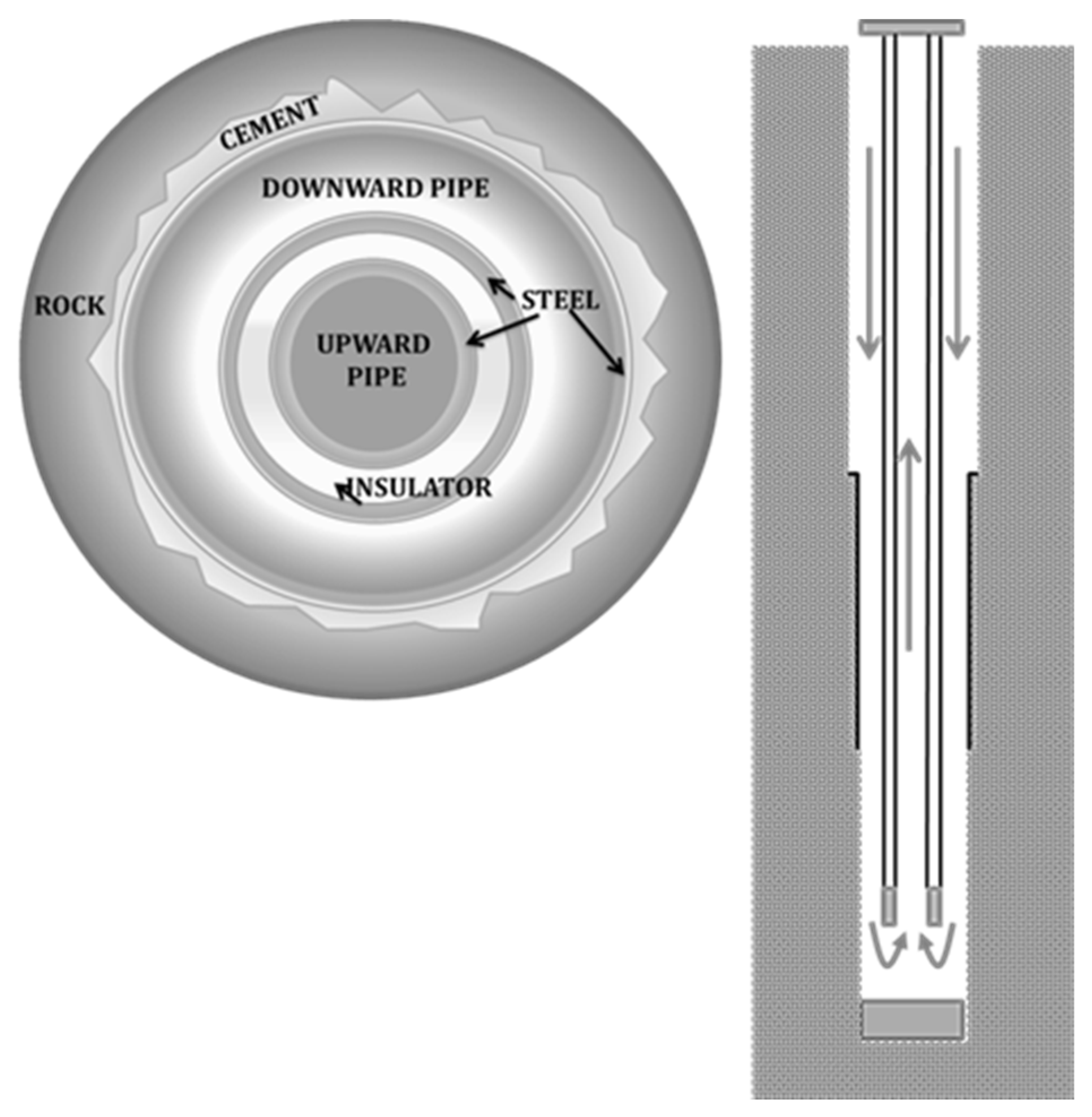
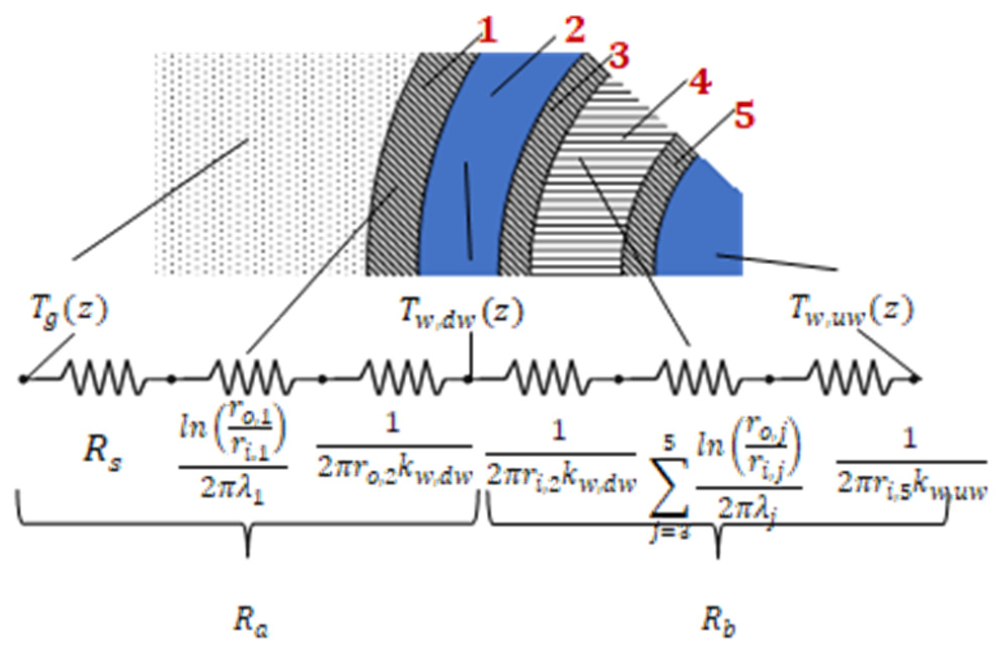
  • WBHX: the thermal power exchanged between the circulating fluid and the far-field ground temperature is evaluated through a series of equivalent thermal resistances. The axial effects are neglected, however, and the temperature evolution of the fluid along the WHBX ducts is evaluated through the so-called “quasi-3D approach” [36,39]. At a given depth, z, the following differential equation applies:
{ m ˙ w c w d T w , d w d z ( z ) = T s ( z ) T w , d w ( z ) R a T w , d w ( z ) T w , u w ( z ) R b m ˙ w c w d T w , u w d z ( z ) = T w , d w ( z ) T w , u w ( z ) R b
where Ra and Rb correspond to the resistances shown in Figure 3. Rs is the transient thermal resistance of the ground: it depends on the ground thermophysical properties and the WBHX operation time [15,40]. In this work, we refer to a year of operation as it corresponds to the period required to get sufficiently close to the steady-state value. Further details are provided in [15,36]. The integration of the set of equations listed in Equation (1) between the inlet and outlet sections of the WBHX provides the profile of the fluid temperature over the downward and upward ducts. The profile of the linear thermal power is evaluated accordingly. Friction losses and pumping requirements are evaluated through the classical Darcy–Weisbach equation using the Moody diagram for fully developed turbulent flows. Thermophysical properties of the water are assumed as dependent on temperature and pressure, therefore the “thermosiphon effect” due to density variation is included in the model, affecting the energy required for pumping. Table 1 summarizes the diameters and the thermal properties of the WBHX layers (see Figure 3).
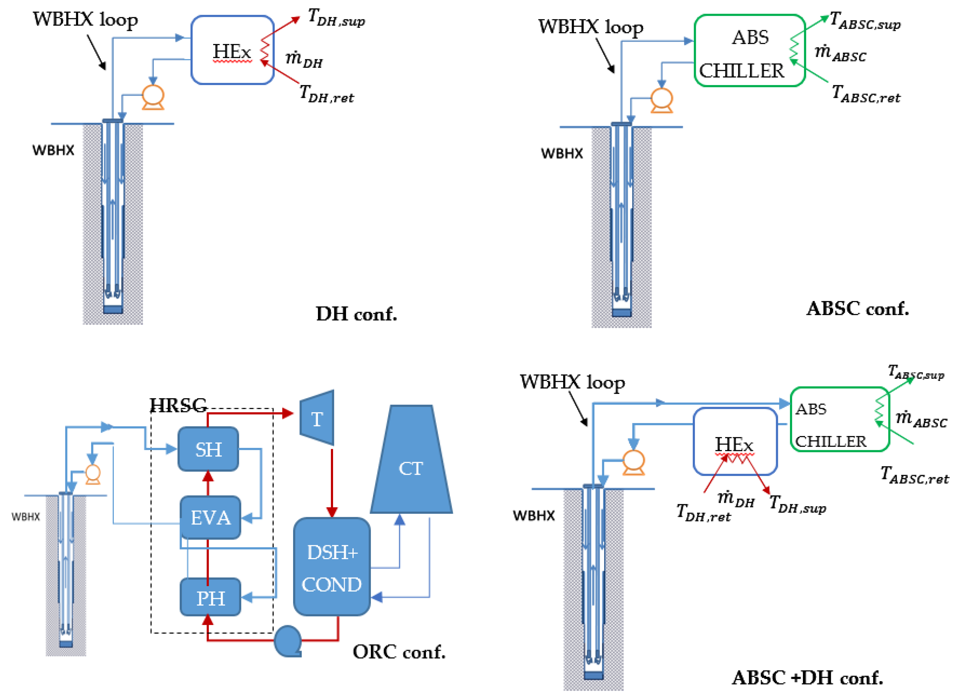
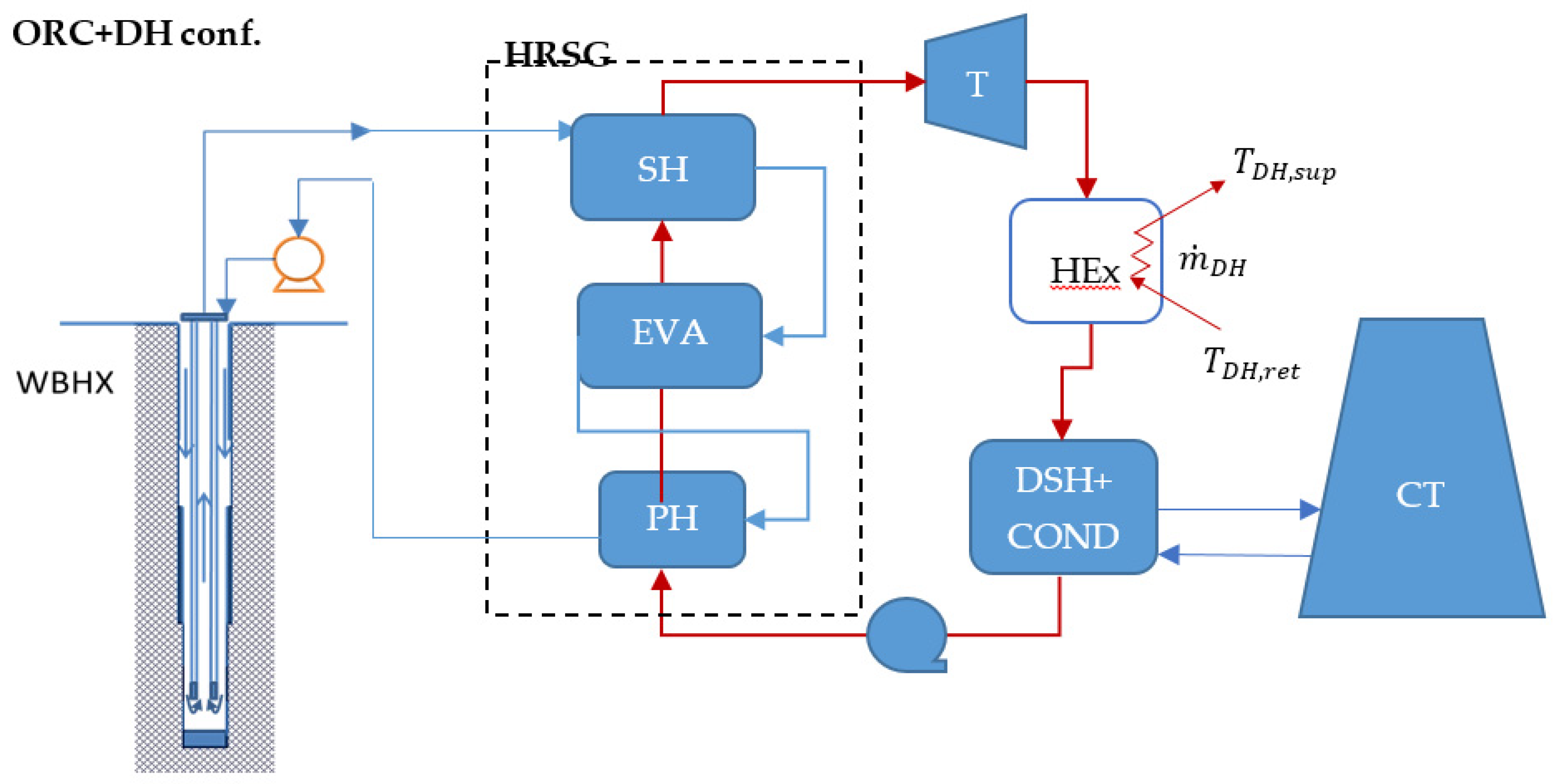
  • District heating: the district heating network is modelled as a water flow to be heated from 60 to 90 °C. The useful flow rate, mDH, and the corresponding thermal power are calculated considering a heat transfer effectiveness of the main DH heat exchanger equal to 0.8. The DH application is only considered if the production temperature of the WBHX must be higher than 100 °C.
  • Absorption chiller: the end-user chiller loop works with supply and return temperatures of 7 and 12 °C, respectively. The chiller is assumed to act as an indirect-fired unit, namely the generator is equipped with a heat exchanger that allows the energy transfer between the hot water from the WBHX loop and the refrigerant mixture (e.g., LiBr-H2O). The temperature required at the generator, Tgen, is assumed equal to 100 °C. The heat exchanger within the ABSC generator is assumed to be sufficiently long to ensure a unitary heat transfer effectiveness: in other words, the WBHX fluid leaves the absorption unit with a temperature equal to the one required in the ABSC generator. The performance of the chiller is evaluated through the second law of thermal efficiency method, according to source temperatures and exergy efficiency, ηIIABSC, assumed as constant and equal to 0.3.
    E E R = η A B S C I I [ 1 T a 1 T g e n 1 T A B S C , s u p 1 T a ]
  • ORC power plant and cooling tower: following the results presented in [36], the considered working fluid is 2-methylpropane (isobutane). Depending on the temperature at the WBHX outlet section, the power of the Hirn cycle is calculated using the following assumption: a condenser temperature equal to 41 °C; a pinch point of the HRSG equal to 5 K; an approach point for all the heat exchangers equal to 10 K; an isentropic and electrical-mechanical efficiency of the turbine equal to 0.85 and 0.95, respectively; and an electrical-mechanical efficiency of the feeding pump equal to 0.6. The power required by the fans in the cooling tower is evaluated according to the model presented in the Appendix of [36]. For each tested configuration, the geometry of the finned surface (i.e., number of rows and number of ducts per row) and the frontal air velocity are optimized to minimize the electricity input, ensuring the required heat exchange at the condenser.
The considered expressions of the exergy efficiency for each configuration is the following:
η D H I I = m ˙ D H ( e x D H , s u p e x D H , r e t ) E x W B H X Q ˙ + W ˙ P , W B H X
η A B S C I I = m ˙ A B S C ( e x A B S C , s u p e x A B S C , r e t ) E x W B H X Q ˙ + W ˙ P , W B H X
η O R C I I = W ˙ O R C , n e t W ˙ P , W B H X E x W B H X Q ˙
η A B S C + D H I I = m ˙ D H ( e x D H , s u p e x D H , r e t ) + m ˙ A B S C ( e x A B S C , s u p e x A B S C , r e t ) E x W B H X Q ˙ + W ˙ P , W B H X
η O R C + D H I I = m ˙ D H ( e x D H , s u p e x D H , r e t ) + W ˙ O R C , n e t E x W B H X Q ˙ + W ˙ P , W B H X
where ex is the physical exergy associated with the fluid stream m and E x W B H X Q ˙ is the exergy associated with the heat flow between the undisturbed ground and the WBHX circulating fluid. The W terms are the input or output electrical power or exergy. The reference environmental state is Ta = 25 °C and pa = 1 bar.
This work presents a sensitivity analysis of the exergy efficiency indexes (see Equations (3)–(7)) depending on the characteristics of the ground source and WBHX geometry. The following parameters and ranges have been considered:
  • Thermal diffusivity of the ground: αg = {10−7; 5 × 10⁻⁷; 10−6} m2/s
  • Thermal conductivity of the ground source: λg = {1; 2; 3} W/(m K)
  • Ground temperature gradient: Kg = {30; 60; 90; 120; 150} K/km
  • WBHX depth: H = {1, 2, 3, 4, 5} km.
Globally, we tested 225 different configurations for each layout in Figure 2. For each tested configuration, the energy and the exergy balance of each component was evaluated through an in-house MATLAB® code.
Obviously, not all of the 225 configurations are suitable for all the application strategies. To be included in the results, the following constraints must be met:
  • The WBHX fluid must be in the liquid state. Proper work pressure and flow rate are thus evaluated for each configuration.
  • The ground temperature at the well bottom must be higher than 100 °C.
  • Configurations resulting in negative exergy efficiency are discarded (e.g., when the auxiliary energy consumption exceeds the power production).

3. Results

The boxplot in Figure 4 summarizes the distribution of the exergy efficiency obtained through the sensitivity analysis discussed in Section 2. The “boxplot” or “box-and-whisker” chart shows the distribution of the plotted quantity: the box goes from the 25th percentile, P25, to the 75th percentile, P75, of the distribution. The difference P75–P25 is called the interquartile range (IQR) and represents a measure of the statistical dispersion. The middle line inside the box corresponds to the median value and the “X” marker corresponds to the mean value. The upper and lower limits of the whisker indicate the maximum and the minimum value, with outliers excluded. The analysis of such a plot allows a better understanding of the general performances of the utilization strategies as it aggregates the results of many simulations, instead of presenting a single case. However, we have selected one configuration to better discuss the main characteristics of WBHX employment according to the final user system (see Table 2).
We note that DH applications have a higher average value of ηII, equal to 0.35, and an IQRDH equal to 0.09. The latter value indicates a constant performance of the DH solution at various WBHX depths and geothermal source conditions. Additionally, DH shows higher thermal power exchanged per well depth, as the lower inlet temperature (70 °C approx.) endorses the WBHX heat exchange. Table 2 also shows that the user equipment (the main HEx) has a limited irreversibility production concerning the well (45 vs. 18 kW).
The ABSC solution has low ηII values (μABSC = 0.1) and a low dispersion (IQRABSC = 0.02). The exegetic performances are mainly affected by the user system technology, namely the absorption chiller. As shown in Table 2, the irreversibility generation in the WBHX is similar to the one occurring in the DH solution, but Iuser almost doubles. Even in favourable operative conditions (Ta = 25 °C), ABSC does not seem to be a proper solution to be used alone because of the exergy efficiency of the absorption equipment (ηIIABSC = 0.3).
Power production through the ORC cycle has an IQRORC value equal to 0.07 and an average equal to μORC = 0.25. These results are coherent with the typical value of binary cycles for geothermal applications. Though electricity has high exergy value, energy production is lower than thermal applications due to the energy efficiency of the ORC plant (~10 %). The heat transfer in the WBHX occurs with an irreversibility production similar to the DH and ABSC solution, but Iuser has the maximum value among all the other utilization strategies.
The combined solution ABSC+DH has a wide range for the ηII value, with the average equal to μABSC+DH = 0.24 and IQRABSC+DH = 0.1. The high variability of performance is due to the relevance of the “low-value” thermal exergy produced by the ABSC for the “high-value” thermal exergy produced by the DH heat exchanger located downstream of the ABSC chiller. This ratio depends on the WBHX flow rate as high mw values increase DH thermal output and reduce the WBHX outlet temperature. The amount of cold energy production depends on a tradeoff between higher flow rate at the ABSC generator and the lower useful temperature drop until reaching TABSC,gen.
In the ORC+DH solution, exergy performances improve versus the ORC solution, thanks to the employment of a recovery heat exchange downstream from the power turbine. The average ηII value is equal to μORC+DH = 0.34 and the IQRORC+DH is equal to 0.11. The performance increase is due to the lower heat to be discharged to the environment and the associated lower exergy destruction and reduced power required to operate fewer fans. Table 2 confirms that power efficiency is practically the same as well as IWBHX in both ORC and ORC+DH case, but Iuser.

4. Discussion and Conclusions

This work has compared and discussed five possible utilization strategies of WBHX technology. Exergy efficiency has been chosen as the main performance index as it allows the comparison of heating, cooling and power production on a homogeneous base. A sensitivity analysis involving 225 well geometry and geothermal source conditions was performed to analyze the exergy efficiency of the considered user systems in different contexts.
The results show a good potential of district heating application as it ensures high values of both useful thermal power and exergy efficiency. Additionally, this application results in one of the most robust user strategies as it ensures good performances at many WBHX depths and source temperatures. The absorption chiller alone does not result in good performance as this technology’s exergy efficiency is too low when producing cooling energy. Power production through ORC technology shows performance similar to the typical values of geothermal binary plants. However, it can only be employed in a limited number of cases, namely when the geothermal source has a sufficient temperature. Moreover, its final performance is affected by a notable uncertainty as the results show a great sensibility to the ground source conditions, which are generally hard to be assessed in practical cases. The employment of the cascade solution as the ORC+DH configuration is confirmed to be attractive in terms of both energy and exergy efficiency, however, the above-mentioned drawbacks on power production remain. Future developments of the present work involve the analysis of other end-user applications and system layouts. Additionally, quantitative criteria to select the most suitable application strategy will be investigated.

Conflicts of Interest

The authors declare no conflict of interest.

Nomenclature

cspecific heat capacity[J/kg K]
ex ˙ specific exergy[kJ/kg]
E ˙ x exergy rate[W]
Kgtemperature gradient[°C/100 m]
I ˙ exergy destruction[W]
IQR interquartile range
kconvective heat transfer[W/m2 K]
Htotal length of the well[m]
m ˙ mass flow rate[kg/s]
ppressure[bar, MPa]
Q ˙ total thermal power[W]
Rthermal resistance[mK/W]
rradius[mm]
Ttemperature[K or °C]
ttime[s]
W ˙ mechanical/electrical power[W]
zdepth[m]

Greek symbols

αthermal diffusivity[m2/s]
ηefficiency
λthermal conductivity[W/m K]
ρdensity[kg/m3]

Subscripts, superscripts, acronyms

aambient state
ABSCabsorption chiller
CPcirculation pump
CTcooling tower
DHdistrict heating
DSH+CONDdesuperheater + condenser
dwdownward
EERenergy efficiency ratio
EVAevaporator
ffluid
gengenerator
HExheat-exchanger
IIsecond-law
iinner
ininlet
oouter
ORCorganic Rankine cycle
outoutlet
Ppump
PHpreheater
retreturn
ssoil property
supsupply
SHsuperheater
Tturbine
upupward
wwater
WBHXWellBore Heat eXchanger
0reference state

References

  1. IRENA. Renewable Capacity Statistics 2019; International Renewable Energy Agency (IRENA): Abu Dhabi, UAE, 2019; ISBN 978-92-9260-123-2. [Google Scholar]
  2. Kujawa, T.; Nowak, W.; Stachel, A.A. Utilization of existing deep geological wells for acquisitions of geothermal energy. Energy 2006, 31, 650–664. [Google Scholar] [CrossRef]
  3. Wang, Z.; McClure, M.W.; Horne, R.N. A single-well EGS configuration using a thermosiphon. In Proceedings of the Thirty-Fourth Workshop on Geothermal Reservoir Engineering Stanford University, Stanford, CA, USA, 9–11 February 2009. [Google Scholar]
  4. Taleghani, A.D. An improved closed-loop heat extraction method for geothermal resources. J. Energy Resour. Technol. ASME 2013, 135. [Google Scholar] [CrossRef]
  5. Akhmadullin, I.; Tyagi, M. Design and analysis of electric power production unit for low enthalpy geothermal reservoir applications. Int. J. Environ. Chem. Ecol. Geol. Geophys. Eng. 2014, 1, 6. [Google Scholar]
  6. Mokhtari, H.; Hadiannasab, H.; Mostafavi, M.; Ahmadibeni, A. Determination of optimum geothermal Rankine cycle parameters utilizing coaxial heat exchanger. Energy 2016, 102, 260–275. [Google Scholar] [CrossRef]
  7. Renaud, T.; Verdin, P.; Falcone, G. Numerical simulation of a Deep Borehole Heat Exchanger in the Krafla geothermal system. Int. J. Heat Mass Transf. 2019, 143, 118496. [Google Scholar] [CrossRef]
  8. Nalla, G.; Shook, G.M.; Mines, G.L.; Bloomfield, K.K. Parametric sensitivity study of operating and design variables in wellbore heat exchangers. Geothermics 2005, 34, 330–346. [Google Scholar] [CrossRef]
  9. Morita, K.; Bollmeier, W.S.; Mizogami, H. An experiment to prove the concept of the downhole coaxial heat exchanger (DCHE) in Hawaii. Trans. Geotherm. Res. Council 1992, 16, 9–16. [Google Scholar]
  10. Kohl, T.; Brenni, R.; Eugster, W. System performance of a deep borehole heat exchanger. Geothermics 2002, 31, 687–708. [Google Scholar] [CrossRef]
  11. Wang, Z.; Wang, F.; Liu, J.; Ma, Z.; Han, E.; Song, M. Field test and numerical investigation on the heat transfer characteristics and optimal design of the heat exchangers of a deep borehole ground source heat pump system. Energy Convers. Manag. 2017, 153, 603–615. [Google Scholar] [CrossRef]
  12. Dai, C.; Shi, Y.; Zeng, L.; Li, J.; Lei, H. Heat Extraction Performance of a Deep Downhole Heat Exchanger. Energy Procedia 2019, 158, 5602–5607. [Google Scholar] [CrossRef]
  13. Galoppi, G.; Biliotti, D.; Ferrara, G.; Carnevale, E.A.; Ferrari, L. Feasibility study of a geothermal power plant with a double-pipe heat exchanger. Energy Procedia 2015, 81, 193–204. [Google Scholar] [CrossRef]
  14. Alimonti, C.; Soldo, E.; Berardi, D.; Bocchetti, D. A comparison between energy conversion systems for a power plant in Campi Flegrei geothermal district based on a WellBore Heat eXchanger. In Proceedings of the European Geothermal Congress 2016, Strasbourg, France, 19–23 September 2016. [Google Scholar]
  15. Alimonti, C.; Soldo, E. Study of geothermal power generation from a very deep oil well with a wellbore heat exchanger. Renew. Energy 2016, 86, 292–301. [Google Scholar] [CrossRef]
  16. Davis, A.P.; Michaelides, E.E. Geothermal power production from abandoned oil wells. Energy 2009, 34, 866–872. [Google Scholar] [CrossRef]
  17. Templeton, J.D.; Ghoreishi-Madiseh, S.A.; Hassani, F.; Al-Khawaja, M.J. Abandoned petroleum wells as sustainable sources of geothermal. Energy 2014, 70, 366–373. [Google Scholar] [CrossRef]
  18. Feng, Y.; Tyagi, M.; White, C.D. A downhole heat exchanger for horizontal wells in low-enthalpy geopressured geothermal brine reservoirs. Geothermics 2015, 53, 368–378. [Google Scholar] [CrossRef]
  19. Noorollahi, Y.; Pourarshad, M.; Jalilinasrabady, S.; Yousefi, H. Numerical simulation of power production from abandoned oil wells in Ahwaz oil field in southern Iran. Geothermics 2015, 55, 16–23. [Google Scholar] [CrossRef]
  20. Wight, N.M.; Bennett, N.S. Geothermal energy from abandoned oil and gas wells using water in combination with a closed wellbore. Appl. Therm. Energy 2015, 89, 908–915. [Google Scholar] [CrossRef]
  21. Mottaghy, D.; Dijkshoorn, L. Implementing an effective finite difference formulation for borehole heat exchangers into a heat and mass transport code. Renew. Energy 2012, 45, 59–71. [Google Scholar] [CrossRef]
  22. Macenić, M.; Kurevija, T. Revitalization of abandoned oil and gas wells for a geothermal heat exploitation by means of closed circulation: Case study of the deep dry well Pčelić-1. Interpretation 2018, 6, 1–9. [Google Scholar] [CrossRef]
  23. DiPippo, R. Second law assessment of binary generating power from low-temperature geothermal fluids. Geothermics 2004, 33, 565–586. [Google Scholar] [CrossRef]
  24. Kotas, T.J. The Exergy Method of Thermal Plant Analysis; Krieger Publishing Company: Malabar, FL, USA, 1995. [Google Scholar]
  25. Lee, K.C. Classification of geothermal resources by exergy. Geothermics 2001, 30, 431–442. [Google Scholar] [CrossRef]
  26. Barbacki, A. Classification of geothermal resources in Poland by exergy analysis—Comparative study. Renewable and Sustainable. Energy Rev. 2012, 16, 123–128. [Google Scholar]
  27. Ramajo, H.; Tritlla, J.; Levresse, G.; Tello-Hinojosa, E.; Ramírez, G.; Pérez, H. New SExI tools to evaluate the evolution and anthropic disturbance ingeothermal fields: The case of Los Azufres geothermal field, México. Rev. Mex. Cienc. Geol. 2010, 27, 520–529. [Google Scholar]
  28. Yari, M. Exergetic analysis of various types of geothermal power plants. Renew. Energy 2010, 35, 112–121. [Google Scholar] [CrossRef]
  29. Ganjehsarabi, H.; Gungor, A.; Dincer, I. Exergetic performance analysis of Dora II geothermal power plant in Turkey. Energy 2012, 46, 101–108. [Google Scholar] [CrossRef]
  30. Fallah, M.; Akbarpour Ghiasi, R.; Hasani Mokarram, N. A comprehensive comparison among different types of geothermal plants from exergy and thermoeconomic points of view. Therm. Sci. Eng. Prog. 2018, 5, 15–24. [Google Scholar] [CrossRef]
  31. Ozgener, L.; Hepbasli, A.; Dincer, I. Thermo-mechanical exergy analysis of Balcova geothermal district heating system in Izmir, Turkey. ASME J. Energy Resour. Technol. 2004, 126, 293–301. [Google Scholar] [CrossRef]
  32. Ozgener, L.; Hepbasli, A.; Dincer, I. Energy and exergy analysis of Salihli geothermal district heating system in Manisa, Turkey. Int. J. Energy Res. 2005, 29, 393–408. [Google Scholar] [CrossRef]
  33. Ozgener, L.; Hepbasli, A.; Dincer, I. Energy and exergy analysis of the Gonen geothermal district heating system, Turkey. Geothermics 2005, 34, 632–645. [Google Scholar] [CrossRef]
  34. Hepbasli, A. Thermodynamic analysis of a ground-source heat pump system for district heating. Int. J. Energy Res. 2005, 29, 671–687. [Google Scholar] [CrossRef]
  35. Kang, S.; Li, H.; Liu, L.; Lei, J.; Zhang, G. Exergy analysis of a novel CHP–GSHP coupling system. Appl. Therm. Eng. 2016, 93, 308–314. [Google Scholar] [CrossRef]
  36. Alimonti, C.; Conti, P.; Soldo, E. A comprehensive exergy evaluation of a deep borehole heat exchanger coupled with a ORC plant: The case study of Campi Flegrei. Energy 2019, 189, 116100. [Google Scholar]
  37. Casarosa, C.; Conti, P.; Franco, A.; Grassi, W.; Testi, D. Analysis of thermodynamic losses in ground source heat pumps and their influence on overall system performance. J. Phys. Conf. Ser. 2014, 547, 012006. [Google Scholar] [CrossRef]
  38. NIST. Standard Reference Database 23: Reference Fluid Thermodynamic and Transport Properties-REFPROP, version 9.1; National Institute of Standards and Technology, Standard Reference Data Program: Gaithersburg, MD, USA, 2013. [Google Scholar]
  39. Conti, P.; Testi, D.; Grassi, W. Revised heat transfer modeling of double-U vertical ground-coupled heat exchangers. Appl. Therm. Eng. 2016, 106, 1257–1267. [Google Scholar] [CrossRef]
  40. Conti, P. Dimensionless maps for the validity of analytical ground heat transfer models for GSHP applications. Energies 2016, 9, 890. [Google Scholar] [CrossRef]
Figure 1. The deep borehole heat exchanger.
Proceedings 58 00020 g001
Figure 2. Reference utilization strategies and systems layout.
Proceedings 58 00020 g002aProceedings 58 00020 g002b
Figure 3. WellBore Heat eXchanger (WBHX) thermal resistance model.
Proceedings 58 00020 g003
Figure 4. Boxplot of exergy efficiency in the 225 tested cases, depending on final utilization strategy.
Proceedings 58 00020 g004
Table 1. WBHX geometry and thermal properties.
ParameterValue
Do/Di Layer 1244.40/226.60 mm
Do/Di Layer 2226.60/177.8 mm
Do/Di Layer 3177.8/150.36 mm
Do/Di Layer 4150.36/88.90 mm
Do/Di Layer 588.90/77.92 mm
Thermal conductivity steel (λ1, λ3, λ5)50 W/(mK)
Thermal conductivity insulation (λ4)0.04 W/(mK)
Table 2. Details on the performance of the five utilization strategies in the case of H = 3 km, Kg = 60 K/km, λg = 2 W/(mK) and αg = 10−7 m2/s.
DHABSCORCDH + ABSCORC + DH
η I I 0.430.100.210.330.24
Q ˙ D H , u s e r 329 kW--2078 kW
Q ˙ A B S C , u s e r -184 kW-140 kW-
W ˙ o u t , n e t --22 kW-22 kW
E x ˙ o u t 47 kW10 kW22 kW37 kW24 kW
E x ˙ o u t /   Q ˙ o u t   o r   E x ˙ o u t / W ˙ o u t , n e t 0.140.0510.1060.8
m ˙ W B H X 5.4 m3/h 5.4 m3/h 5.4 m3/h5.4 m3/h 5.4 m3/h
Q ˙ W B H X 329 kW196 kW298 kW356247 kW
T f , W B H X , i n 73 °C100 °C80 °C68 °C90 °C
T f , W B H X , o u t 125 °C130 °C126 °C123 °C130 °C
E x W B H X Q ˙ 109 kW92 kW105 kW113 kW99 kW
I ˙ W B H X 45 kW48 kW44 kW45 kW45 kW
I ˙ u s e r 18 kW35 kW39 kW31 kW29 kW
Publisher’s Note: MDPI stays neutral with regard to jurisdictional claims in published maps and institutional affiliations.

