Abstract
In this work we make use of the frequency diverse array (FDA) concept, whose design is based upon a frequency increment across the antenna elements to generate a beam steering that is a function of angle, time and range. For a possible use of this technique in 5G detection systems, a 28-GHz FDA numerical model, designed with help of a software tool, is analyzed. Some practical conclusions are drawn from the presented results.
1. Introduction
The next-generation of cellular network (5G) is approaching evolution beyond the mobile Internet to the IoT (Internet of Things) in the near future, with the expectation of communications being available everywhere. 5G is transforming the wireless telecommunication arena, paving the way for the next generation of cellular networks that will include more devices and will enable faster communications through higher speeds. Presumably, the devices technologies will have to adapt to this new approach through the adopted frequency bands. Among many frequency spectra, the millimeter band has been considered as a good candidate for 5G cellular communications, since it provides higher data rate services because of increased channel bandwidth compared to lower frequency bands [1]. A promising antenna technology for utilizing millimeter band communications was introduced [2,3], namely, frequency diverse array (FDA).
FDA is a technology that employs frequency increment across the array elements. With such a technology, beam steering is achieved by applying a linear phase progression across the aperture, creating both a deformation of the antenna pattern in the steering process and a limited scanning.
2. System Description of the Numerical 28-GHz FDA Model
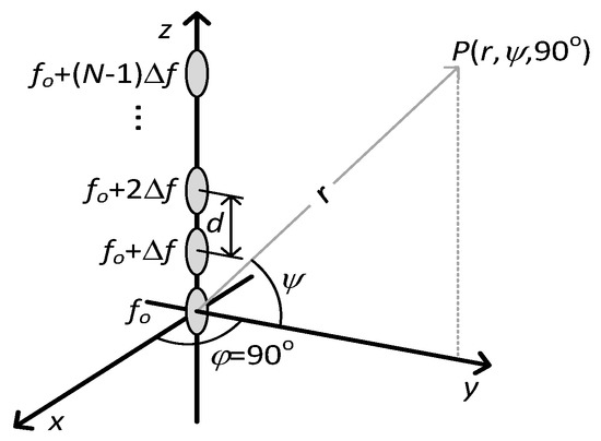
Let us consider an N-element FDA [1,2] whose main axis is aligned along the z axis and whose inter-element distance between contiguous elements is a constant value d (see Figure 1). For a case study, we will set the array by using circular patches whose normals are pointing towards the y axis and that, for the sake of simplicity, will be considered to radiate a cos2ψ-type power pattern [4]. To further simplify the analysis, the static excitations of the elements will be uniform (i.e., In = 1, for n = 0, 1, …, N − 1). Besides, the yz plane (φ = 90°, see Figure 1) will be taken for representing the main radiation pattern with ψ varying from −90° to 90°. Under those assumptions, the beam power pattern at point P(r, ψ, 90°) will be proportional to [1,2]:
where c is the speed of light in vacuum, λc = c/fc is the wavelength at the carrier (working) frequency fc, r is the range (distance) measured from the center of the array coordinate system (see Figure 1) and Δf is the frequency shift that produces the range-dependent behavior of the FDA pattern [1,2].

Figure 1.
Linear FDA composed of circular patches.
3. Results and Future work
Let the nominal scan angle (ψ) be zero, indicating that the beam is not intentionally scanned by means of a linear phase progression across the array. As a specific case, we consider a 10-element cos2-FDA whose inter-element distance is d = λc/2, radiating at fc = 28 GHz, and with Δf = 15 kHz.
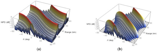
We can see the comparison between the Normalized Power Density (NPD in dB) (The NPD is obtained by taking the logarithm with base 10 of the power pattern normalized with respect to the overall maximum radiation value within the considered angle ψ and distance r coverages) obtained with an FDA composed of 10 isotropic elements (with all the parameters set to the above mentioned values) (Figure 2a); and the corresponding NPD of a cos2-FDA presented in this work (Figure 2b), both with −90° ≤ ψ ≤ 90° and r ranging from 20 to 60 km. Those plots were obtained with the help of Mathematica® software tool [5].

Figure 2.
(a) Normalized Power Density (NPD) of a 10-element 28-GHz FDA with isotropic elements. (b) NPD of a 10-element 28-GHz cos2-FDA.
The beamforming effect for both the isotropic FDA (Figure 3a) and cos2-FDA (Figure 3b) at a given range is obtained by changing the shift frequency. For those plots, a constant range r = 20 km was taken for three values of Δf (10, 15 and 20 kHz).

Figure 3.
Impact of frequency offset on the main beams. (a) Isotropic elements FDA NPD. (b) Cos2-FDA NPD. In both cases, r = 20 km, and Δf = 10 kHz: dotted line; Δf = 15 kHz: continuous line; Δf = 20 kHz: dashed line.
It can be seen from the above figures that the element power pattern (cos2ψ in our case) not only affects, as is well known, the pattern sidelobes (lowering them towards angles deviating from the broadside) but also the steering capabilities of the FDA, thus reducing the main lobe level for both range r (see Figure 2) and frequency shift Δf (see Figure 3) changes. Those effects are not in any way negligible therefore, for practical cases, alternative studies must be performed to correct them.
The presented numerical simulations show that the use of FDAs at a 5G working frequency (28 GHz) is possible. But from the above considerations, some corrections are needed, even for the general case (i.e., at frequencies not necessarily equal to the one chosen in this work) and this could be taken as a future work. Another research line could be focused on a full-wave simulation of the presented model with a proper electromagnetic simulation software tool.
Author Contributions
Conceptualization, and methodology, M.B.A.A. and J.B.; software, J.B.; Investigation, R.M., J.A.G.-N.; resources, L.C.; writing, M.B.A.A.; Funding acquisition, L.C.
Funding
This research received This work has been funded by the Xunta de Galicia (ED431G2019/01), the Agencia Estatal de Investigación of Spain (TEC2016-75067-C4-1-R, RED2018-102668-T, PID2019-104958RB-C42) and ERDF funds of the EU (FEDER Galicia & AEI/FEDER, UE).
Conflicts of Interest
The authors declare no conflict of interest.
References
- Kim, T.; Park, J.; Seol, J.; Jeong, S.; Cho, J.; Roh, W. Tens of Gbps Support with Mmwave Beamforming Systems for Next Generation Communications. In Proceedings of the 2013 IEEE Global Communications Conference, Atlanta, GA, USA, 9–13 December 2013; pp. 3679–3685. [Google Scholar] [CrossRef]
- Nusenu, S.Y.; Basit, A. Frequency Diverse Array Antennas: From Their Origin to Their Application in Wireless Communication Systems. J. Comput. Netw. Commun. 2018, 2018, 5815678. [Google Scholar] [CrossRef]
- Secmen, M.; Demir, S.; Hizal, A.; Eker, T. Frequency Diverse Array Antenna with Periodic Time Modulated Pattern in Range and Angle. In Proceedings of the 2007 IEEE Radar Conference, Boston, MA, USA, 17–20 April 2007; pp. 427–430. [Google Scholar] [CrossRef]
- Antonik, P.; Wicks, M.C.; Griffiths, H.D.; Baker, C.J. Frequency Diverse Array Radars. In Proceedings of the IEEE Radar Conference, Verona, WI, USA, 2006; pp. 215–217. [Google Scholar] [CrossRef]
- Hastings, C.; Mischo, K.; Morrison, M. Hands on Start to Wolfram Mathematica, 2nd ed.; Wolfram Media, Inc.: Champaign, IL, USA, 2016. [Google Scholar]
Publisher’s Note: MDPI stays neutral with regard to jurisdictional claims in published maps and institutional affiliations. |
© 2020 by the authors. Licensee MDPI, Basel, Switzerland. This article is an open access article distributed under the terms and conditions of the Creative Commons Attribution (CC BY) license (https://creativecommons.org/licenses/by/4.0/).