Abstract
Computational fluid dynamics is recently being considered as an interesting tool to predict and analyze surfboards’ hydrodynamic characteristics for the purpose of optimizing the design. In this paper we define a systematic methodology that could be used to measure forces and moments exerted by the fluid on the surfboard. We define a “surfboard attitude” matrix, for instance varying the angle of attack and the tip surfacing height, and we fill it with values of drag, lift and moment. With these data, we can calculate the position of the center of pressure and analyze static equilibrium conditions in the presence of external forces that represent the weight of a surfer.
1. Introduction
Surfboard hydrodynamics is a complex subject due to the extremely large number of degrees of freedom that characterize the problem. For example, the same surfboard can be ridden by different surfers (different weight, inertia, feet distance) with different styles (time varying force and application points) on different waves (variable speed, steepness, etc.). A few papers have recently appeared that show preliminary simulations of maneuvers but only with imposed maneuvering trajectories [1]. Other publications considered different surfboards and compared their hydrodynamic characteristics [2]. However, most numerical simulations involving surfboards focus on surfboard fins [3,4,5,6], whose behavior is simpler to simulate than the complete surfboard. Despite these clear difficulties, that still require time to be overcome, computational fluid dynamics (CFD) can be considered a useful tool to evaluate the basic hydrodynamic characteristics of surfboards for optimal design purposes.
Here we propose a methodology aimed at computing drag, lift and pitch moment on a generic surfboard, and we use the results to identify surfboard equilibrium attitudes under the effect of an external weight force that simulates the presence of a surfer.
2. Method
2.1. Physical and Numerical Modelling
We carried out a numerical analysis using the CFD simulation software STAR-CCM+ (Build 14.02.010). Liquid water and gaseous air phases were treated using the Eulerian multiphase model and coupled with the volume of fluid (VOF) approach. The latter is an interface-capturing method that predicts the distribution and the movement of the interface of immiscible phases. The flow was assumed to be turbulent. The Menter’s version of the Shear-Stress Transport (SST) k-ω model was used to provide closure to the Reynolds-averaged Navier–Stokes (RANS) equations. Preliminary tests have been carried out using the k-ε closure model also, but no significant differences have been found between the results, at least in terms of forces acting on the surfboard. The governing equations were integrated in time with second order accuracy using the implicit unsteady solver embedded in STAR-CCM+.
2.2. Surfboard Geometry and Attitude Parameters Definition
The aim of this paper is defining a methodology to numerically evaluate surfboard hydrodynamic characteristics. For this reason, we were not particularly interested in a specific surfboard geometry and we simply used a surfboard CAD (computer-aided design) geometry freely available online [7]. We just changed the fins because the CAD geometry was not adequate to CFD meshing. The CAD geometry of the three new fins was also downloaded from the web [8].
To perform a parametric study about forces and moments acting on the surfboard at different attitudes, we univocally defined some geometrical parameters, some concerning the surfboard geometry, such as, for example, its length, its maximum width and its maximum thickness, and others related to the attitude, such as the angle of attack, the depth of submersion and/or the height of surfacing of the nose tip. Surfboards are symmetric with respect to the centerline plane, so we used the “profile” of the surfboard, that is the butt line given by the intersection of the surfboard with the centerline plane, to define the “chord” of the surfboard. This is illustrated in Figure 1, where we show that the chord of the surfboard is the segment that joins the leading edge and the trailing edge of the profile, that is the fore and aft points of maximum curvature, respectively. Using such a definition, the chord length, c, normally coincides with the maximum longitudinal extension of the surfboard. For the purpose of this paper, we could define the angle of attack (also AOA, or α) simply as the angle formed by the chord and the flat-water surface. In realistic situations, when the surfboard planes on a curved and inclined wave, such a definition will have to be generalized in a different way. Finally, we could use the distance of the surfboard’s nose from the water plane, h, as the independent parameter that also dictates the length of the submerged portion of the chord and the depth of submersion of the tail, d, that is the distance between the tail and the flat-water surface. The chord of the surfboard that we used in this work was equal to 1.904 m.
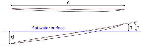
Figure 1.
Geometrical definitions of chord, angle of attack, tip height of surfacing and tail depth of submersion.
2.3. Numerical Mesh and Boundary Conditions
Since the VOF approach assumes that the mesh is sufficiently resolved to capture the position and the shape of the interface between the phases, attention had been directed to refining the mesh. Different grid resolutions have been considered until a final grid providing mesh-converged results was defined. A visual example of the adopted grid is shown is Figure 2. The computational domain is 21 m long in the x-direction, that is in the flow direction, 10 m in the y-direction, which is normal to the surfboard symmetry plane, and 7.5 m in the z-direction, which is normal to the flat-water surface. The latter lays at 5.0 m from the bottom of the computational domain. The tip of the surfboard was always placed at 6.0 m from the right side of the computational domain. The mesh had been refined at the water/air interface: a layer of thin cells with a 3.5 mm length in the direction normal to the flat-water surface extends from a depth of 5 cm to a height of 7 cm above the flat-water level. Other layers with decreasing mesh size had also been superimposed to ensure a smooth mesh transition. The region around the surfboard required further attention. Hexahedral and cylindrical boxes that rotate and translate according to the surfboard’s attitude were placed around the surfboard to locally refine the grid. The box nearest to the surfboard’s surface contained cubic cells with sides the size of 3.5 mm. The surfboard surface mesh had a target cell dimension of 7 mm, with the possibility of reaching a minimum size of 0.88 mm depending on the surface curvature. The target surface mesh size had been reduced to 3.5 mm on the fins. The result was a grid containing about 5.8 million cells.
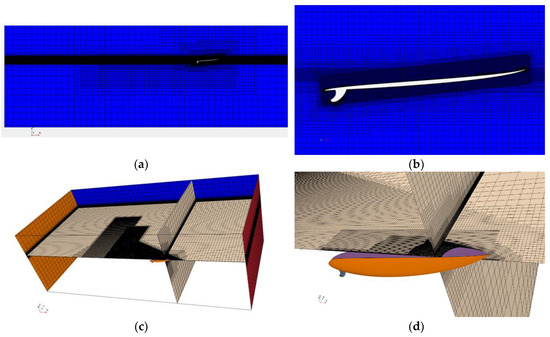
Figure 2.
The computational mesh; (a) complete view at the symmetry plane; (b) zoomed view at the symmetry plane near the surfboard; (c) complete view of the computational domain; (d) mesh details near the surfboard.
Boundary conditions enforced uniform velocity in the x-direction for both water and air at the y-z plane upstream from the surfboard and pressure outflow conditions downstream. This was equivalent to towing the surfboard at the inflow velocity. A symmetry plane was placed in correspondence with the surfboard centerline plane (x-z plane), so that only half of the physical domain was simulated. At the bottom and top planes, we imposed the same velocity boundary condition of the inlet (in this case the velocity vector was parallel to the surface) and finally a symmetry boundary condition was set at the external x-z plane.
3. Results and Discussion
We carried out a systematic analysis about forces and moments on the considered surfboard at different attitudes and speeds. The initial conditions were uniform velocity and pressure (with values identical to the inflow condition) for both water and air, and a flat water/air interface. Then, the simulation evolved in time for at least 10 s, but in some cases the final time was extended up to 20 s to obtain constant mean values of the hydrodynamic forces. The angle of attack, α, varied from 0° to 12° with a 2° step, and the surfacing height of the tip, h, changed from 0 to 8 cm with a 2 cm step, and from 8 to 24 cm with a 4 cm step. Some (h,α) couples, in particular those with a large h in combination with a small α, have not been simulated because they would result in unphysical configurations (flying surfboard). The final solutions were weakly unsteady, with oscillations of about 1% in the magnitude of forces and moments. We defined as lift, L, and drag, D, the forces normal to the flat-water surface and parallel to the velocity vector, respectively. Since these forces lay on the x-z plane, we only calculated the moment about the y-axis, My with respect to the surfboard tip. For conciseness, only data concerning a speed of 6 m/s are shown here in Figure 3, Figure 4 and Figure 5. Note that the values refer to half the surfboard, so they must be multiplied by two to obtain the correct magnitude. As expected, forces and moments tend to increase as the angle of attack increases and as the tip surfacing height .
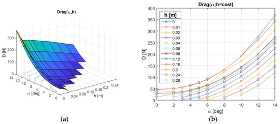
Figure 3.
Drag force on half surfboard.
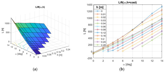
Figure 4.
Lift force on half surfboard.
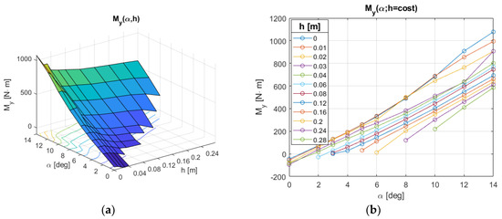
Figure 5.
Moment about the y-axis with respect to the tip on half surfboard.
Given drag, lift and y-moment with respect to the tip, it is possible to calculate the position of the center of pressure on the chord. This is shown in Figure 6, where it is possible to see that, for moderate surfacing lengths, the center of pressure lays at about 40% of the chord for most angles of attack.
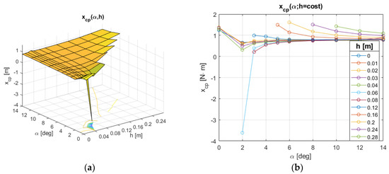
Figure 6.
Center of pressure position along the chord.
A static equilibrium analysis can also be carried out considering external forces that should simulate the presence of a surfer on the surfboard. Here, for the sake of simplicity, we considered the external force as applied in a single point, but nothing prevents the split of the surfer weight in two contributions that might be placed at different positions along the chord. Considering the surfboard weight also, that we estimate to be 2.874 kgf (and that we divide by two as we are considering just half the surfboard for symmetry reasons), the static equilibrium equations read like:
where and represent the position of the center of gravity along and above the chord, respectively, and T is the traction force in the x-direction that must equilibrate the drag. For simplicity, we assumed that traction was applied at the center of gravity, as it could be done in a towing experiment. In our case, we have 1.018 m and 0.02938 m. Given a certain external force , for each couple (h,α) a position may exist that ensures static equilibrium. Clearly, not all combinations are valid since some may not fulfill Equation (1a), or may fall outside the surfboard. In Figure 7a we show different static equilibrium positions for two different external forces corresponding to surfer weights of 50 kgf and 70 kgf, respectively. The plots have been obtained interpolating the functions D(h,α), L(h,α) and My(h,α) to increase the data resolution. The available equilibrium positions cover a belt in the (h,α) plane and range from about 0.74 m to 1.25 m from the surfboard tip. These are stable static equilibrium conditions, as we verified calculating the eigenvalues of the Jacobian matrix of Equations (1a) and (1b). One example of the wave system around the surfboard for a given equilibrium condition is shown in Figure 7b. It corresponds to an external weight of 70 kgf placed at x = 0.85 cm from the surfboard tip. The iso-surface corresponds to a water fraction equal to 0.5 that roughly corresponds to the air/water interface. Superimposed colors indicate the height with respect to the flat-water level.
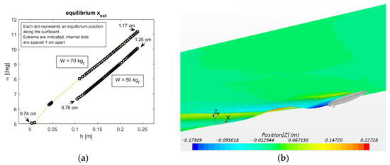
Figure 7.
(a) Equilibrium positions for external forces of 50 and 70 kgf (dots indicate force position with spacing of 1 cm between indicated extrema; (b) surfboard and air/water interface for one equilibrium state (colors indicate the height with respect to the flat water level, only the computed half-domain is shown).
4. Conclusions
Extensive CFD simulations on surfboards at different attitudes can be carried out with the aim of obtaining a map of the hydrodynamic characteristics. These data can be used to compare the performance of surfboards of a similar class, or to verify the effect of geometry changes. Surfboard stability and equilibrium conditions in the presence of external forces can also be evaluated and might be used as a further tool to define surfboard performance quality.
References
- Oggiano, L.; Pierella, F. CFD for Surfboards: Comparison between Three Different Designs in Static and Maneuvering Conditions. Proceedings 2018, 2, 309. [Google Scholar]
- Oggiano, L. Numerical Comparison between a Modern Surfboard and an Alaia Board using Computational Fluid Dynamics (CFD). In Proceedings of the 5th International Congress on Sport Sciences Research and Technology Support, Funchal, Madeira, Portugal, 30–31 October 2017; pp. 75–82. [Google Scholar]
- Gudimetla, P.; Kelson, N.; El-Atm, B. Analysis of the hydrodynamic performance of three- and four-fin surfboards using computational fluid dynamics. Aust. J. Mech. Eng. 2009, 7, 61–67. [Google Scholar] [CrossRef]
- Falk, S.; Kniesburges, S.; Janka, R.; Grosso, R.; Becker, S.; Semmler, M.; Döllinger, M. Computational hydrodynamics of a typical 3-fin surfboard setup. J. Fluids Struct. 2019, 90, 297–314. [Google Scholar] [CrossRef]
- Lavery, N.; Foster, G.; Carswell, D.; Brown, S. CFD Modelling of the Effects of Fillets on Fin Drag. Reef J. 2009, 1, 93–111. [Google Scholar]
- Sakellariou, K.; Rana, Z.A.; Jenkins, K.W. Optimization of the Surfboard Fin Shape using Computational Fluid Dynamics and Genetic Algorithms. Proc. Inst. Mech. Eng. Part P J. Sports Eng. Technol. 2017, 231, 344–354. [Google Scholar]
- Quilha Central FCS. Available online: https://grabcad.com/library/quilhas-1 (accessed on 13 November 2019).
- Surfboard Thruster. Available online: https://grabcad.com/library/surfboard-thruster-1 (accessed on 13 November 2019).
Publisher’s Note: MDPI stays neutral with regard to jurisdictional claims in published maps and institutional affiliations. |
© 2020 by the author. Licensee MDPI, Basel, Switzerland. This article is an open access article distributed under the terms and conditions of the Creative Commons Attribution (CC BY) license (https://creativecommons.org/licenses/by/4.0/).