1. Introduction
A force plate system is used for the measurement of a ground reaction force. The force plate of this system outputs 3-axis force and 3-axis moment components. The force plate consists of four load cells, and the force and moment are calculated by the load cell signals [
1]. The force components are calculated by the sum of load cell signals, and the moment components are calculated by the sum and difference of load cells signals. This calculation is conducted based on the Newton–Euler method [
2], and the calculations do not consider the moment generated on load cells. The force plate system consists of a base plate, load cells, an amplifier circuit, and a top plate. Previous force plate systems have been installed with four 3-axis load cells. Therefore, an effect of torsion in the top plate generated by an external force caused the measurement error in the previous force plate system. The top plate in the force plate system is thick and heavy to ensure stiffness. The force plate system consists of a calculation function for compensating for errors in the load cells signal and the effect between the plates and load cells. However, the force and moment error are generated by the torsion of the top plate. Furthermore, previous compensation methods cannot compensate force and moment generated on the outside of load cells.
The effect of torsion of the top plate involves a moment generated on the load cells. Hence, we can develop a high-performance force plate system by developing load cells that can measure the moment about the torsion of a top plate, and the load cells are installed to the force plate system. In this study, we developed a new force plate system consisting of 5-axis load cells. The load cells can measure a 3-axis force and a 2-axis moment. The moment indicates the component about the torsion of a top plate. Furthermore, we indicate the performance and effectiveness of the developed force plate through measurement and analysis using a wearable sensor system.
2. Force Plate System
The developed force plate system is shown in
Figure 1. This system installs with 5-axis load cells, a load cell output, a 3-axis force (
fx,
fy,
fz), and a 2-axis moment (
mx,
my). The force plate signals are calculated by the load cells signals. The size of the force plate is 400 mm × 600 mm × 60 mm. The weight is 22 kg. The rated output is
Fx: ±2000 N,
Fy: ±2000 N,
Fz: 6000 N,
Mx: ±1200 N·m,
My: ±900 N·m,
Mz: ±400 N·m.
Calculation of force and moment is conducted based on the Newton–Euler method [
1]. The calculation of force is shown in Equation (1), and the calculation of moment is shown in Equation (2), where
M is the moment vector,
fi is the force signal outputted from the load cell, and
0pi is the position vector from the original point to the load cell [
3].
The force plate signals include the error of the load cells signal and the error caused by the attachment of the plate and loadcells. These errors are compensated by the cross-talk compensation matrix. The matrix is generated by the optimal calculation and the calibration device, and these calculations can be combined in the calculation of force and moment. The calculation matrix is shown in Equation (3), where
Fx,comp~
Mz,comp are the compensation values of force and moment.
N11~
N66 are the cross-talk compensation elements. The elements are obtained by using the optimal calculation, force plate signal, and the calibration device signal.
In previous force plates, the number of load cell signals (strain values) is twelve or eight. The load cell signals are translated by using full bridge circuit (
εfz) or half bridge circuit by two load cell signals (
εfx,
εfy,
εmx,
εmy) in Wheatstone Bridge circuits, where
εfx1~
εmy2 are the load cell signals (strain values). In the force plate system installed with the 5-axis load cells, the signals number is twelve by including a half bridge circuit in shearing force (
εfx,
εfy) and moment (
εmx,
εmy). The load cell outputs are translated to the force plate outputs by using the translational matrix extended Equation (3). The matrix is shown in Equation (4),
Cj,k are the elements that combine both a matrix for cross-talk compensation (Equation (3)) and a calculation matrix of force and moment (Equations (1) and (2)).
The matrix can be estimated by using the optimal value estimation method and the calibration device. The Extended Kalman filter was used for estimating the transformation matrix, and the special calibration device for force plates was used for calibrating the previously developed force plate (TF-4060, TF-6090, TF-90100, Tec Gihan Co. Ltd., Kyoto, Japan). The compensation matrix was calculated by using the calibration device, and the matrix was installed to a special amplifier circuit.
3. Verification Experiment
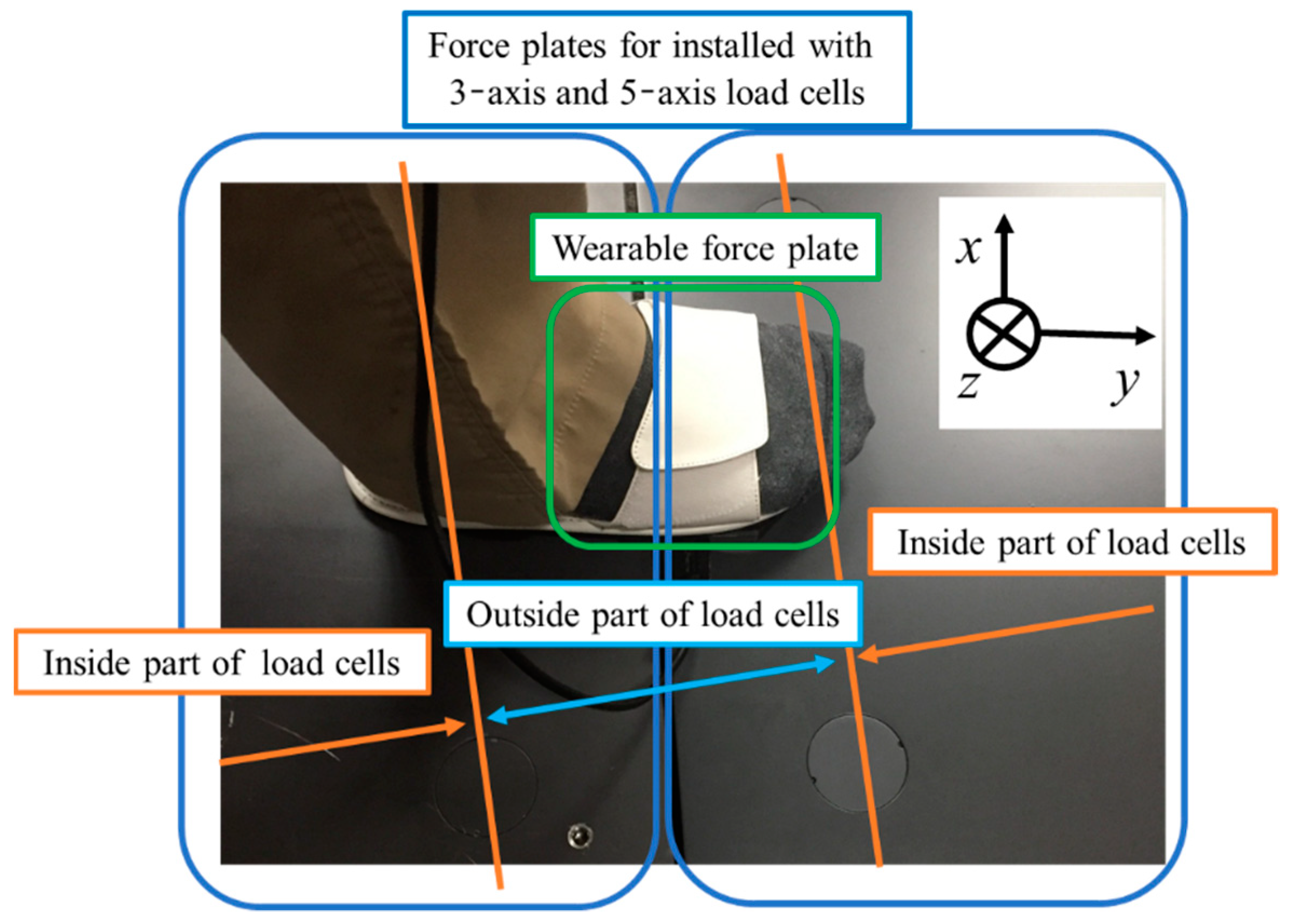
We conducted a verification experiment to confirm the accuracy of the force plate system. The two standard types of force plates (TF-4060, Tec Gihan Co. Ltd.) and two developed force plates were installed in a straight line. The experimental view is shown in
Figure 2.
In the experiment, forces were generated between the force plates by stepping between the force plates. The force was measured from a gait motion by using a wearable sensor system (wearable force plate) (M3D force plate, Tec Gihan Co. Ltd.) for the verification [
3]. The wearable force plate installs an inertial sensor. The 3D posture (Roll and Pitch angles) in global coordinates is estimated by the inertial sensor signals and the Kalman filter [
4], and the force and moment signals in the wearable force plate (sensor coordinate system) were translated to a global coordinate system. The wearable force plate is shown in
Figure 3. The total force in force plates and the wearable force plate signals were compared. The experimental view is shown in
Figure 4. The sampling frequency is 1000 Hz, and the measurement time is 10 s.
4. Experimental Results
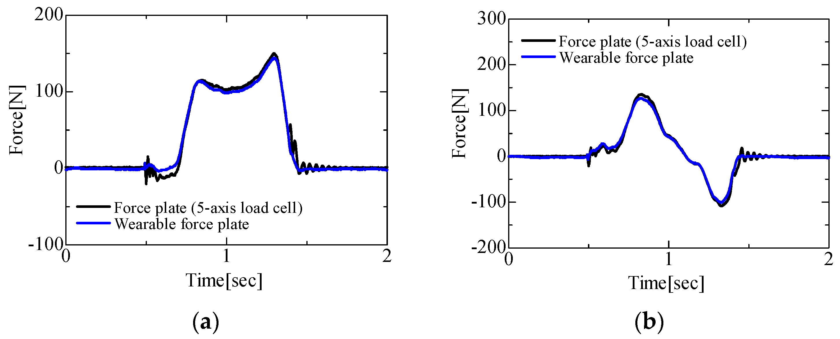
Results for the 3-axis force components obtained by the force plates installed with 3-axis and 5-axis load cells and the wearable force plate are shown in
Figure 5 and
Figure 6. In the results of the force plate installed with 3-axis load cells and the wearable force plate, the
Fz (vertical direction) component results are in agreement. However, errors were generated in the results of
Fx (lateral direction) component.
In the results for the force plate installed with 5-axis load cells and the wearable force plate, all component results were in agreement. The root mean square errors were calculated in between the force plates and the wearable force plate. In the force plate installed with 3-axis load cells and the wearable force plate, the root mean square errors were Fx: 9.64 N, Fy: 9.98 N, Fz: 10.29 N. In the force plate installed with 5-axis load cells and the wearable force plate, the root mean square errors were Fx: 6.43 N, Fy: 6.24 N, Fz: 8.16 N. The error of Fx is bigger than other results, and the max value of error in near peak (0.8–1.2 s) are 14.24 N in the force plate installed with 3-axis load cells and 6.17 N in the force plate installed with 5-axis load cells. Therefore, the results indicated the effectiveness of force plate installed with 5-axis load cells.
5. Conclusions
In this study, we developed a new force plate system installed with five-axis load cells. The load cells measure a 3-axis force and a 2-axis moment. Therefore, this system can consider the effect of the torsion of top plate and compensation in measurement of outside parts of the load cells (
Figure 3) using the moment components. The verification experiment using the force plates installed with the 3-axis load cells and the 5-axis load cells and the wearable force plate can indicate the performance of a developed force plate in the measurement between the force plates. The performance of the force plate is higher than the performance of a force plate installed with the 3-axis load cells. Therefore, the ground reaction force measurement of high performance in sports can be conducted using the developed force plate.


