Proceeding Paper

Modelling Bending Stiffness and Vibration Characteristics to Enable Simulation-Driven Ski Design †

1
Department of Industrial and Materials Science, Chalmers University of Technology, SE-412 96 Gothenburg, Sweden
2
Department of Mechanics and Maritime Sciences, Chalmers University of Technology, SE-412 96 Gothenburg, Sweden
*
Author to whom correspondence should be addressed.
Presented at the 13th conference of the International Sports Engineering Association, Online, 22–26 June 2020.
Proceedings 2020, 49(1), 157; https://doi.org/10.3390/proceedings2020049157
Published: 15 June 2020

Abstract

:
When developing alpine skis, new design is often built upon experience from what has been done in the past. This allows for stable but incremental improvements that limit the possibilities of ground-breaking design changes. To allow such major changes, without risking spending a fortune on trial and error studies, simulation-based design is a must. This paper presents a method for such a simulation-based design approach, focusing on the effect of the internal ski structure and its effect on bending and vibration characteristics. As a prototype ski, we have studied Faction Skis’ Candide 3.0, for which a finite element model was developed and validated. In the next step, the effect of a design ski variation was analysed to demonstrate how simulation-based screening of design options can be easily implemented.

1. Introduction

The skiing industry is in constant development, with new product line releases every season. Still, when developing new skis, model updates are generally incremental and based on experience from older models. This traditional approach makes it hard to predict the effect both from radical design changes and from the introduction of new materials, without an expensive and slow trial and error process. It also slows down the transition to more sustainable materials.
In contrast, product development in other business sectors is strongly driven by predictive simulations of new concepts prior to physical testing. The aim of the current work has therefore been to develop a method for predicting ski properties based on Finite Element analysis, with focus on the bending stiffness along the ski’s main axis and its lowest eigenfrequencies, and to illustrate how such a method can be utilised for screening the effect on stiffness and vibration characteristics from modifications to the internal material structure of the ski.
Early attempts to predict ski properties based on numerical analysis and simulation were performed by Clerc et al. [1] and later by Nordt et al. [2]. Although being able to reasonably well predict the bending stiffness characteristics, these studies were based on 1-D beam analysis, making them difficult to extend to study torsion, local stress distributions, risks for delaminations and snow contact. More recently, Federolf et al. [3] published a study where a combination of shell and solid elements was used to represent the ski. However, despite that “comprehensive parameter studies and validation experiments were conducted” [3], the error in bending predictions were around 15%. In another recent work, Wolfsperger et al. [4] increased the level of detail significantly and modelled the entire ski using solid elements for each internal layer. Although being very accurate in stiffness predictions (~3% maximum error), such a detailed model makes it difficult to study internal changes in the ski structure. In the current work, the aim has been to find a method to represent the ski bending with enough accuracy. At the same time, the ski model should be flexible enough to easily allow for changes in the internal structure such that design changes can be easily realised. Furthermore, in addition to bending stiffness characteristics, the ski model should also be able to predict relevant eigenfrequencies, and it should be representative also for studying internal stress distributions to investigate damage events (not presented here).

2. Materials and Methods

2.1. The Ski Candide 3.0

The prototype ski considered in this study is Candide 3.0 from Faction Skis, see Figure 1a, with a length of 182 cm, widths (shovel/waist/tail): 137.8/108/132.5 mm and a FIS radius of 20 m. A principal sketch of its cross-section is shown in Figure 1b, where specific geometry features have been removed or idealized not to reveal the exact design. From bottom to top it has a base material layer of Ultra-High Molecular Weigh Polyethylene (PE-UHMW), a glass fibre textile-reinforced composite layer, a wood core (composed of strips of different types of wood glued together), a mounting plate in Titanal, another glass fibre textile-reinforced composite layer and finally, a polymer top sheet layer. In addition, the ski has steel edges for good gripping in the snow and polymer sidewalls on opposite sides. As the focus of the current work is on the internal ski structure, the effect of plates and bindings are disregarded. Thereby, a ski without these features is considered both in the physical experiments and in the numerical modelling.

2.2. Experimental Testing

Of interest in the current study was to validate the numerical finite element model, see Section 2.3, both towards bending stiffness and vibration characteristics. Although torsion is critical for ski performance, this was excluded in the current study due to challenges related to finding a clearly defined load case and boundary conditions with good correlation between the physical experiment and the numerical model.

2.2.1. Three-Point Bend Test for Stiffness Characteristics

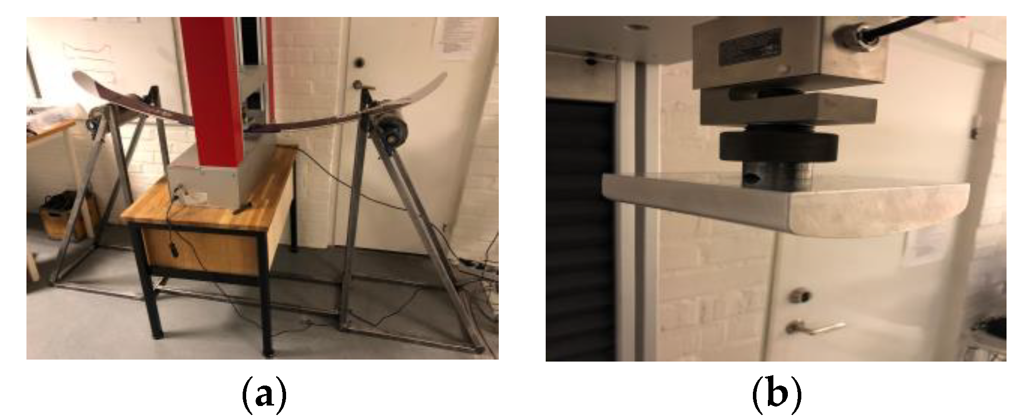
To obtain experimental stiffness data to validate the numerical model, a simple three-point bend test rig was designed and manufactured. The rig was inspired but not entirely designed according to the specifications in ISO 5902:2013 [5]. In detail, it consisted of a stiff supporting structure of steel square tubes, cf. Figure 2a, designed to hold two supporting rollers with a diameter of 128 mm, situated 1300 mm apart (centre-centre distance). To minimise frictional effects, the rollers were connected to the supporting steel frame via four ball bearing plummer block units (UCP 204).
A finite element analysis of the structural deformation of the rig at the anticipated maximum load was performed prior to manufacturing to make sure that rig deformations could be neglected. As the rig displaced less than 1% of the expected ski deflection under maximum load, the rig was stiff enough not to introduce errors in the model validation.
In addition, to avoid local crushing of the ski in bending, a curved pressing tool was designed with the requirements: (i) to have a large radius to obtain at the maximum contact pressure much lower than the compressive through-thickness strength of the ski materials (2.2 MPa at maximum load) and (ii) to be easily incorporated in the FE-model. As a result, a single radius tool with a radius of 146 mm (much higher than the ISO standard) was designed, cf. Figure 2b.
The supporting rig was then centred under a uniaxial tension/compression machine and a total of eight repeated bend tests, up to a maximum machine cross-head displacement of 130 mm, were conducted. In between all tests, the ski was rotated 180 degrees to reduce configuration bias.

2.2.2. Experimental Modal Analysis

Two important dynamic properties that determine the dynamical behaviour of a ski are its eigenfrequencies and its damping. Although the effective ski damping heavily relies on ski-snow interaction [6], we focus here on the inherent vibration characteristics of the ski itself, with the main aim to validate the numerical model for further screening of design modifications.
As the prevailing standard for ski bending vibrations (ISO 6267:1980) mainly provides a measure to characterise only the first bending mode, a modal analysis was instead performed. In this test, the ski was balanced upon three rubber cushions, cf. Figure 3a, to isolate the ski from its surroundings. An accelerometer (PCB, type 352C22) was attached on the bottom surface close to the frontal tip of the ski (location marked by ‘Sensor’ in Figure 3b) and vibrations were induced by impacting the ski with an instrumented hammer at 12 different positions, cf. the red dots in Figure 3b. To average out inconsistent hits, each position was hit five times. Both the hammer and the accelerometer were connected to a data acquisition system, DT9837A, produced by DataTranslation. Using the identification toolbox in MATLAB (Mathworks Inc., 2018), each collection of five tests was averaged into one result for each impact position. System identification was then carried out using the data for the 12 responses (see e.g., red curve in Figure 5a below). From the data, it was estimated that a model order in the range of 18 to 30 was necessary to represent the system and capture all major eigenfrequencies of the ski.

2.3. Mechanical Modelling and Simulation

2.3.1. The Finite Element Model of the Ski

The finite element model of the Candide 3.0 ski was developed in ANSYS Workbench with the corresponding composite pre- and post-processing modules (ANSYS ACP). For this model, the geometry of the ski was generated as an equivalent shell structure based on data supplied by Faction Skis. A shell representation was chosen over a solid representation to allow for a modelling approach that can easily incorporate changes of the internal structure. This is sufficient for the current study but will require additional consideration in an extension to consider ski-snow contact.
A schematic of the ski-lay-up is given in Table 1, where also the primary bending stiffness characteristics (longitudinal stiffness for anisotropic materials) and density of each material is included. Exact layer thicknesses and materials are proprietary and cannot be disclosed. To handle the varying core materials across the width, the ski model was split in segments along its length such that for each segment, a different core property could be assigned (corresponding to the actual type of wood). Furthermore, the varying core thickness along the length of the ski was implemented through interpolation of tabular data of discrete thickness measurements along the ski length, using a built-in function the ACP-toolbox of ANSYS. The ski was discretised into a total of 1352 linear quadrilateral shell elements (approx. 15 mm element size) which gave mesh convergent results.
To include the stiffening effect from the side walls and the steel edges without adding model complexity, these were replaced by an equivalent part with the geometry of the side walls and equivalent material stiffness yielding the same average bending stiffness contribution (found through a separate detailed finite element analysis of the bending of a side wall and steel edge).

2.3.2. Load Cases

Three-Point Bend Test

To model the three-point bend test, a geometrically non-linear analysis was performed. For this analysis, the ski model was supported by two cylindrical fixed supports modelled as rigid and frictionless (as the rollers in the tests were free to rotate). In addition, the bending load on the ski was enforced through (assumed) frictionless contact with a displacement controlled rigid model of the tool. Furthermore, the rigid body translation of the ski was prevented in its longitudinal direction by displacement constraints enforced at the ski centre. The reaction force due to the prescribed motion of the tool was recorded and used for comparison with the recorded force during the experiment.

Simulated Modal Analysis

To replicate the two experimental vibration tests, the modal toolbox of ANSYS was utilised. As enough data on the damping characteristics of the different materials was lacking, only the undamped (natural eigenfrequencies) could be predicted. However, for a system with little expected damping, the natural and damped frequencies are very close. To mimic the experimental modal analysis test, the ski model was constrained in the horizontal plane but made free to deflect in the vertical direction, thus imitating the ski supported by the rubber balls.

3. Results

3.1. Three-Point Bend Test

The force measurements from the eight bend tests were within 0.5% difference from the mean value at each displacement value. Thus, only the mean value of all eight curves is shown below. The comparison between experimentally measured and simulated force-displacement relations is shown in Figure 4a, where it can be observed that the physical tests are within the range of the simulated results using the lower (approx. 7% mean deviation from experimental results) and higher (approx. 11% mean deviation from experimental results) values for the fibre-reinforced layers. As this was the major uncertainty in the modelling, simulation results were also generated with a fibre-reinforced layer stiffness of E = 27 GPa. As can be seen in Figure 4b, this yielded excellent agreement with the physical test results for the entire displacement range.

3.2. Modal Analysis

The vibration response was recorded for all impact points in the experimental modal analysis, although only data for impact point A1 is reported herein. As can be seen from the test data and the identified model response in Figure 5a, several well-defined eigenfrequencies could be identified. The values together with the corresponding damping coefficients and the finite element predictions (for low and high stiffness) are all summarised in Table 2. The first bending mode predicted from the finite element analysis is also shown in Figure 5b,c.

4. Concluding Remarks and Outlook

The results indicate that even though there were large uncertainties in some of the material data, the proposed single-layer shell model is sufficiently detailed to capture the bending behaviour and the lowest eigenfrequencies with acceptable accuracy. It was further shown that by tailoring the stiffness of the glass fibre layers within the uncertainty range of the data, excellent agreement could be obtained. However, for such excellent agreement, nonlinear geometrical effects need to be accounted for. As the next step, it would be interesting to investigate the ability of the model to predict the local bending characteristics along the ski and compare that with experimental data found, e.g., through the method proposed by Truong et al. [7].
To illustrate how the method can be used to design stiffer (or lighter) skis, we finally demonstrate the effect of replacing the current wood core structure with a pure balsa core (protected on the sides with thin strips of poplar of negligible width) and by replacing a fraction of the glass fibre layers with a carbon fibre composite (longitudinal stiffness of 209 GPa, density of 1540 kg/m3). As can be seen in Figure 6 (solid black line), the ski becomes approximately twice as stiff even though the total mass is reduced by approximately 10%. It is emphasized that further efficient screening of material solutions is enabled by having a single-layer shell modelling approach compared to high-fidelity modelling with detailed solid modelling.

Acknowledgments

The authors gratefully acknowledge the financial support of this project from Chalmers Sports and Technology through the Area of Advance Materials Science at Chalmers University of Technology.

Conflicts of Interest

The authors declare no conflict of interest.

References

  1. Clerc, C.; Gaertner, R.; Trompette, P. Computer aided design of skis. Finite Elements Analysis Design 1989, 5, 1–14. [Google Scholar] [CrossRef]
  2. Nordt, A.A.; Springer, G.S.; Kollár, L.P. Computing the mechanical properties of alpine skis. Sports Eng. 1999, 2, 65–84. [Google Scholar] [CrossRef]
  3. Federolf, P.; Roos, M.; Lüthi, A. Finite Element Simulation of the Ski-Snow Interaction in a Carved Turn in Alpine Skiing. Sports Eng. 2010, 12, 123–133. [Google Scholar] [CrossRef]
  4. Wolfsperger, F.; Szabo, D.; Rhyner, H. Development of alpine skis using FE simulations. Procedia Eng. 2016, 147, 366–371. [Google Scholar] [CrossRef]
  5. International Organization for Standardization. (2013). Alpine Skis — Determination of Elastic Properties. ISO Standard No. 5902. Available online: https://www.iso.org/standard/60844.html (accessed on 3 June 2020).
  6. Schwanitz, S.; Griessl, W.; Leilich, C.; Krebs, R.; Winkler, B.; Odenwald, S. The Effect of a Vibration Absorber on the Damping Properties of Alpine Skis. Proceedings 2018, 2, 305. [Google Scholar]
  7. Truong, J.; Brousseau, C.; Lussier Desbiens, A. A Method for Measuring the Bending and Torsional Stiffness Distributions of Alpine Skis. Procedia Eng. 2016, 147, 394–400. [Google Scholar] [CrossRef]
Figure 1. (a) Top view of Faction Candide 3.0; (b) schematic cross-section at the centre of the ski.
Proceedings 49 00157 g001
Figure 2. (a) Three-point bend test set-up; (b) close-up of the single radius tool.
Proceedings 49 00157 g002
Figure 3. Experimental modal analysis: (a) rubber supports and (b) impact points and sensor location (sensor placed on the bottom surface).
Proceedings 49 00157 g003
Figure 4. Comparison between experimental and simulation results from tree point bending test: (a) with simulated results using original stiffness values for the fibre-reinforced layers (low = 20 GPa and high = 35 GPa) and (b) with longitudinal stiffness for the fibre-reinforced layers of 27 GPa.
Proceedings 49 00157 g004
Figure 5. (a): Frequency response of data (black) and matching system model response (red) for position A1; (b): upper endpoint of first eigenmode; (c): lower endpoint of first eigenmode.
Proceedings 49 00157 g005
Figure 6. Illustration how the proposed method can be used to analyze the change in ski stiffness when altering the internal ski structure (replacing glass fibres with carbon fibres).
Proceedings 49 00157 g006
Table 1. Lay-up of Candide 3.0 with corresponding longitudinal stiffness and density for each layer.
Ski Lay-Up (Bottom to Top)Longitudinal 1 Stiffness [GPa]Density [kg/m3]
Top sheetVery low stiffness, i.e., not included 8050
Top fabric layer25/3522000
Mounting plate (Titanal)722820
Core (Poplar/Balsa/Ash/Beech/Paulownia)10.9/3.7/12.3/14.3/4.4455/150/680/720/280
Bottom fabric layer25/3522000
Base material (PE-UHMW)0.9940
1 In case of an anisotropic material. 2 Due to discrepancies between Supplier Data Sheet (low) and Factions experience (high), two values were used.
Table 2. The five lowest eigenfrequencies and corresponding damping coefficients obtained from experimental modal analysis from impacting point A1 together with simulated eigenfrequencies using the finite element model.
Exp. Eigenfreq. (Hz)Exp. Damp. Coeff.Num. Eigenfreq.—
High Stiffness (Hz)
Num. Eigenfreq.—
Low Stiffness (Hz)
9 0.003312 11
62 0.001754 49
67 0.006180 77
97 0.0098110 106
141 0.0044 130 119
Publisher’s Note: MDPI stays neutral with regard to jurisdictional claims in published maps and institutional affiliations.