Abstract
A 470 sailing race requires effective cooperation between athletes to optimize the hull position and the correct heading. To understand the effect of the hull on the maneuverability of the rudder and the influence of the rudder on the stability and rapidity of the hull at different ship speeds, requires numerical 3D simulation and research on the viscous flow field of 470 sailing based on Reynolds-averaged Navier-Stokes equations. The results show that the rudder can reduce the wave making characteristics of the hull, reducing energy loss and thus improving the hull’s rapidity when the speed is greater than 6 m/s, as the effective area of rudder decrease and increases the stall angle, which reduces the manipulatable performance of the rudder to some extent. This study could quantify the performance of the hull and rudder at different speeds. Moreover, this study might provide strategies for the athletes to effectively control the rudder and hull at different speeds.
1. Introduction
The 470 sailing is an Olympic sailing event in which two teammates tacitly cooperate with the sailboat for racing in the complex sea conditions of certain sea areas. Generally, the speed of the yacht ranges from 2 to 10 m per second within the regular races. Each race will go through the process of multiple rounds of headwind, downwind, and crosswind, fully testing the cooperation between the two athletes in adjusting the sail wing system and optimizing the hull position and correct heading by controlling the rudder, to make the sailing boat obtain enough power. In the course of the sailing competition, the athletes often fall behind in the ship’s deceleration ranking caused by the failure of coordination in the process of sailing and circling the standard. Scientific and systematic research on the interaction between the rudder control and the ship’s position can realize the perfect coordination between the athletes, which has practical benefits for the athletes allowing them to improve their competitive ability. Therefore, the basic research on the hydrodynamic performance of sailing equipment will become very important.
Through research on the dynamic performance of sports equipment, former scholars can make athletes familiar with the overall operation performance of sports equipment to complete technical actions more efficiently. Parolini et al. (2005) [1] studied the America Cup yacht by solving the Reynolds-averaged Navier-Stokes equations and towing tank testing, including the optimization of hull performance of fully equipped sailboats under different motion conditions, the effect of hull appendage on hull performance, the influence of crew position on hull position [2], and the improvement of accuracy of numerical simulation method [3], so as to achieve the America Cup championship.
In terms of Olympic sailing, Ma Yong et al. [4,5] used numerical simulation and towing tank methods to study the fluid performance of windsurfing and sail. On the basis of summing up the law of resistance changing with speed under the condition of the longitudinal and transverse inclination of the windsurfing board and analyzing the influence of the wing camber, the angle of attack, the angle of buckle, the mast etc. on the aerodynamic performance of board, he put forward the strategy of adjusting windsurfing for sailing, the cross tail wind section, and the vicinity of the standard, which provides reference for the control of the board and sail wing. His team’s research promotes that China won the windsurfing championship in 2008 and the laser women’s championship in 2012.
Vidmar et al. (2013) [6] studied the simple steering system and a hydrodynamic shaped single rudder, or multiple rudders, depending on upwind sail boat characteristics. Rickard et al. (2014) [7] investigated the hydrodynamic resistance prediction using Computational Fluid Dynamics (CFD) and towing tank testing for the better position of Laser sailing. Huetz et al. (2014) [8] optimized the hull shape based on statistical methodology to treat the database. Through the total station, the shape measurement and drawing model of the 470 sailing yacht and laser yacht have been completed, and the numerical simulation of the no wave laser trim hull position, wave navigation, and interaction between the stable plate and hull of the 470 sailing yacht has been carried out [9,10]. The study of the interaction between the hull and the rudder will help to adjust the equipment reasonably, realize the control of the high speed and stability of the sailboat, and ensure the sailboat will complete the race according to the strategic route of the athletes.
2. Computational Method
2.1. Governing Equations
The Navier-Stokes equations are based on the assumptions that fluid around the hull and the rudder is incompressible. This study adopted Reynolds-averaged Navier-Stokes equations and continuity equations as governing equations to simulate the yacht without trim and heeling; the general speeds in actual races are 2 m/s, 4 m/s,6 m/s,8 m/s, and 10 m/s, and the rudder angle range measured is from 0 to 40 degrees. In Cartesian coordinates, the continuity equation and the momentum equation can be expressed as follows [11]:
Continuity equation:
Momentum conservation equation:
whereis average velocity and is fluctuation velocity(i = 1,2,3), is the fluid density, t is time, is the kinetic viscosity of the fluid, is body force, and is turbulent influence.
2.2. Mesh Generation and Domain Boundary
The hull-rudder parameters are shown in Table 1. The weight of the hull is 118 kg, and the weight of the two athletes ranges from 110 kg to 180 kg. The displacement is assumed to be 280 kg in this study. The grids were meshed in ICEM CFD 15.0. As shown in Figure 1 and Figure 2, the simulations are carried out on a Cartesian grid for the hull and a hybrid grid for the hull-rudder assembly. The computational domain size is chosen as 7 L × 6 L × 2 L (L is the length of hull) with approximately 5 million grids in total. The region around the rudder and hull model with high-resolution unstructured grids is employed to capture the boundary layer and satisfy the distance of the first neighbor grid and y+ = 60~100. At the upstream boundary of the hull, it is a constant inflow velocity boundary condition. The downstream boundary is the pressure-outlet boundary, availing simulation iteration convergence. The bottom boundary is the moving wall, and the wall of the hull and the rudder are no slip walls. The symmetry boundary condition is provided at all other boundaries [11].

Table 1.
Parameters of 470 Sailing yacht [11].
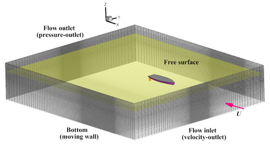
Figure 1.
Schematic of the computational mesh and boundary conditions employed in the present simulations.
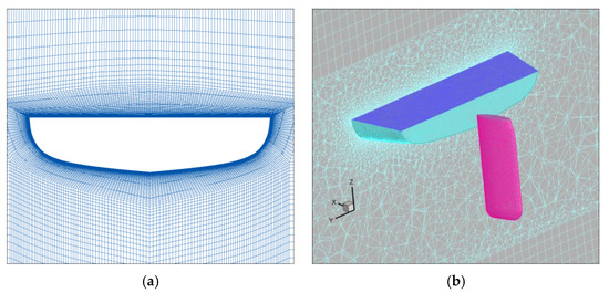
Figure 2.
Schematic of the computational mesh of hull and rudder: (a) is hull and (b) is rudder [11].
3. Numerical Results and Analysis
In order to understand the influence of the hull on the maneuverability of the rudder at different hull speeds and the influence of the rudder on the stability and rapidity of the hull at different ship speeds, this paper used Reynolds-averaged Navier-Stokes equations to simulate the viscous flow field of 470 sailing by ANSYS 15.0. Considering the impact of free liquid, we used the Volume of Fraction (VOF) method and the Shear Stress Transport (SST) turbulence model to simulate the fluid, and the numerical simulation of this model was analyzed through a first-order upwind difference scheme.
The rudder may have a substantial impact on the stability and rapidity of the hull, so this paper analyzes the resistance and lateral forces of the hull and the lift and drag of the rudder. The dimensionless expressions were as follows:
Drag Coefficient of Hull:
Lateral Force Coefficient of Hull:
Drag Coefficient of Rudder:
Lift Coefficient of Rudder:
where is drag force of hull and is lateral force of hull, is wet area of hull when the displacement is 280 Kg. is drag force of rudder, is lift force of rudder, is wet area of rudder, and is inflow velocity.
3.1. Hydrodynamic Analysis of the Influence of Rudder on Hull
In this section, this paper aims to understand the effect of the rudder interaction on the hydrodynamic performance of the hull when the rudder turns from 0 degree to 40 degrees at the velocities 2 m/s, 4 m/s, 6 m/s, 8 m/s, and 10 m/s. We extracted the resistance and lateral force of the hull for analysis, as shown in Figure 3; the drag coefficient is distributed at 0.01 and the lateral force coefficient is around 0. It is hard to find the rudder increase the resistance and lateral force of the hull.
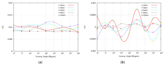
Figure 3.
The result of relation between hull force coefficient and leeway angle: (a) is hull drag and (b) is lateral forces.
Evident in Figure 4 is that the rudder has an impact on the wake profile behind the hull. Figure 4a shows the wake profile of the naked hull is complex and fully flowing, and Figure 4b shows the rudder reduces the waveform of the hull wake effectively and makes the wake profile asymmetrical, weakening the waveform and saving energy. In summary, the rudder plays the role of rectifying the plate and reducing the wave-making ability of the hull, saving energy and thus improving the hull’s rapidity.
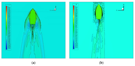
Figure 4.
The wake profile of 470 Sailing: (a) naked hull and (b) hull-rudder assembly.
As shown in Figure 5, when the inflow velocity is less than 6 m/s the resistance of the hull is almost unaffected by the rudder, while when the velocity exceeds 6 m/s the presence of the rudder causes the drag to decrease compared to the naked hull. Therefore, the rudder can reduce the wet area and drag of the hull when the speed is greater than 6 m/s.
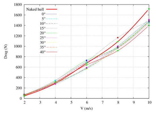
Figure 5.
The result of relation between hull resistance and speed.
3.2. Manipulative Analysis of the Influence of Hull on Rudder
Figure 6 presents the lift coefficient of the rudder with the leeway angle in some speeds, as shown in Figure 6a, the stall angle is about 15 degrees, and the lift coefficient of the rudder assembly is changed with the leeway angle shown in Figure 6b. At 2–6 m/s, the stall angle is about 30 degrees, while the stall angle increases to 35 degrees when speed reaches 8 m/s to 10 m/s. Compared with the free liquid surface wave cloud diagram of the rudder assembly in Figure 4b, the hull wake is caused by the increase of the ship speed. The effective area of the rudder body continues to decrease, and the aspect ratio is reduced to increase the stall angle of the rudder body. The data results of the comprehensive numerical test and the results of the free surface cloud analysis show that as the speed increases, the hull wake increases the stall angle of the rudder when the velocity is greater than 6 m/s.
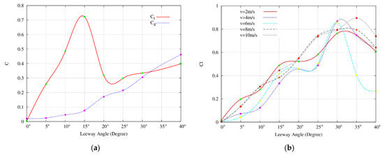
Figure 6.
The relationship between the coefficient of force and leeway angle: (a) is naked rudder and (b) [11] is rudder on the hull.
4. Conclusions
This paper investigates the hydrodynamics of 470 sailing at different hull speeds using the commercial software ANSYS 15.0. The results showed that the rudder can reduce the wave-making characteristics of the hull, reducing energy loss and thus improving the hull’s rapidity when the speed is greater than 6 m/s. The wake wave of the hull reduces the effective area of the rudder, and the stall angle increases which reduces the manipulatable performance of the rudder to some extent. Our findings could enhance the understanding of coaches and athletes on the performance of the hull and rudder at different speeds. Moreover, our study might provide strategies for the athletes to effectively control the rudder and hull at different speeds.
Funding
This research was funded by National Natural Science Foundation of China grant number 51679183, the East Lake Scholars Sponsorship Program of Wuhan Sports University and Double-First-Class Construction Projects.
Conflicts of Interest
The authors declare no conflict of interest.
References
- Parolini, N.; Quarteroni, A. Mathematical models and numerical simulations for the America’s Cup. Comput. Methods Appl. Mech. Eng. 2005, 194, 1001–1026. [Google Scholar] [CrossRef]
- Mylonas, D.; Sayer, P. The hydrodynamic flow around a yacht keel based on LES and DES. Ocean Eng. 2012, 46, 18–32. [Google Scholar] [CrossRef]
- Viola, I.M.; Enlander, J.; Adamson, H. Trim effect on the resistance of sailing planning hulls. Ocean Eng. 2014, 88, 187–193. [Google Scholar] [CrossRef]
- Ma, Y.; Tang, Y.H.; West, N.; Zhang, Z.Y.; Lin, S.J.; Zheng, Q.Z. Numerical Investigation on Trimming of a Single Sail in a Regatta. Sports Eng. 2016, 19, 81–90. [Google Scholar] [CrossRef]
- Lei, X.S.; Ma, Y.; Lin, S.J. Comparative Study of an Aerodynamic Performance of the Neil Pryde RS: X Class at Different Wind Speeds Based on One-way and Two-way Fluid-Structure Interaction Methods. China Sport Sci. Technol. 2019, 55, 51–56. [Google Scholar]
- Vidmarn, P.; Perkovič, M. Optimization of upwind sailing applying a canting rudder device. Ocean Eng. 2013, 73, 55–67. [Google Scholar] [CrossRef]
- Levin, R.L.; Finnsgård, C.; Peter, J. Hydrodynamic Resistance Prediction of an Olympic Class Sailing Dinghy Using CFD and Towing Tank Testing. In International Congress on Sports Science Research and Technology Support; Springer: Cham, Switzerland, 2014; pp. 85–106. [Google Scholar]
- Huetz, L.; Guillerm, P.E. Database building and statistical methods to predict sailing yacht hydrodynamics. Ocean Eng. 2014, 90, 21–33. [Google Scholar] [CrossRef]
- Lin, S.J.; Ma, Y.; Zheng, Z.; Zheng, Q.Z.; Tang, J.T. Investigation on hull Hydrodynamics with different trim angles for Laser Radial Class Yacht. J. Wuhan Inst. Phys. Educ. 2016, 50, 98–93. [Google Scholar]
- Zhang, S. Hydrodynamic Performance of Laser Radial Class in Regular Head Waves. Master’s Thesis, Wuhan Sports University, Wuhan, China, 2019. [Google Scholar]
- Lin, S.J.; Ma, Y.; Zheng, W.T.; He, Y.Y.; Tang, J.T.; Lei, X.S.; Zhang, S.; Qiu, B. Investigation on rudder application for 470 Class Yacht based on mechanical analysis. China Sport Sci. 2017, 37, 25–32. [Google Scholar]
Publisher’s Note: MDPI stays neutral with regard to jurisdictional claims in published maps and institutional affiliations. |
© 2020 by the authors. Licensee MDPI, Basel, Switzerland. This article is an open access article distributed under the terms and conditions of the Creative Commons Attribution (CC BY) license (https://creativecommons.org/licenses/by/4.0/).