Proceeding Paper

Difference of Reynolds Crisis Aspects on Soccer Balls and Their Panels †

1
Graduate School of Kogakuin University, Tokyo 163-8677, Japan
2
Kogakuin University, 1-24-2 Nishi-Shinjuku, Shinjuku-ku, Tokyo 163-8677, Japan
*
Author to whom correspondence should be addressed.
Presented at the 13th Conference of the International Sports Engineering Association, Online, 22–26 June 2020.
Proceedings 2020, 49(1), 117; https://doi.org/10.3390/proceedings2020049117
Published: 15 June 2020

Abstract

:
The soccer ball panel pattern, which changes every World Cup, greatly affects the ball’s aerodynamics and flight characteristics. In this study, the fluid force of 11 soccer balls with different panel patterns was measured by wind tunnel tests. The drag crises with different Reynolds numbers were confirmed depending on the panel shape. To understand this, the shapes of panel grooves were measured and the relationship between them was investigated. The flow separation point was also visualized by the oil film method and the particle image velocimetry (PIV) analysis. The separation points were confirmed to be different depending on the panel groove by the oil film method in a supercritical Reynolds region. The flow separation points were found to be almost the same position in the subcritical and supercritical state and to be partly different around the Reynolds number of drag crisis.

1. Introduction

The patterns of recent soccer balls are greatly different from that of the conventional soccer ball, with several changes being made to the shape and design of the surface of the ball. Various aerodynamic studies on soccer balls have been reported. Passmore et al. [1] described the FIFA-approved balls and argued that that, although the drag characteristics were different for the different balls, the simulation suggested that this had only a limited effect on the flight of the ball. Goff et al. [2,3] reported the aerodynamic difference of non-spinning several soccer balls by the different panel shapes. Hong et al. [4] showed that the separation point changed depending on the number of seams by a 2D-particle image velocimetry (PIV) method. The authors of [5] reported that the aerodynamic forces acting on the ball differed corresponding to its orientation and rotation. Murakami et al. [6] measured the aerodynamic forces of soccer balls and made a tuft grid visualization to investigate the wake structure behind a ball. However, the relationship between the groove shape and the aerodynamic characteristics on the Reynolds number region around the drag crisis has not yet been clarified.
In this study, the different aerodynamic characteristics of the different panels of soccer balls was investigated, and the relationship between the groove shape and drag crisis phenomenon was confirmed. The 2D-PIV analysis was also conducted on the different orientations of balls, and the reason for the different aspects of the drag crisis by the different panels was investigated.

2. Method

The following four kinds of experiment were performed on the following soccer balls: the fluid force experiment to measure the aerodynamic performance, the groove shape measurement to determine the surface properties, the oil film experiment to confirm the separation lines of each panel, and PIV analysis to confirm the separation points on the Reynolds number around drag crisis phenomena. Table 1 summarizes the 11 balls used for the experiments. It is recognized that the number of ball panels and their shape differ greatly. All the balls examined had a diameter of 0.22 [m]; the air pressure was set all 90 [kPa].

2.1. Fluid Force Experiment 1

Drag measurements were performed on 11 kinds of different soccer balls with a wind tunnel and a three-components load cell whose maximum load was 50.0 N on each component. The samplings were conducted at 1000 Hz for 9.0 seconds from a wind speed of 3 to 29 m/s in every 1 m/s under computer control, and the experimental values were averaged. The balls bonded with a double-sided tape attached with a support cup were attached with a cobra type support. The coefficient of drag, the CD, was defined through the following equation, where D, ρ, U and A denote the ball drag in N, the density of air, uniform wind velocity, and projected cross-sectional area of the ball, respectively:
C D = D 1 2 ρ U 2 · A

2.2. Groove Shape Measurement

The groove length in the panel joint of each ball was measured by putting strings in all grooves. The cross-sectional area and the dimensions of the groove were taken with a one-shot 3D-shape instrument by VR-3000, KEYENCE. The depth length and sectional area were obtained with an accuracy of 1.00 × 10⁻³ [m] and 1.00 × 10⁻⁶ [m2]. The total groove volume was calculated by multiplying and summing the groove length and the same cross-sectional area.

2.3. Oil Film Experiment/2D-PIV Measurement

A mixture of oleic acid, liquid paraffin, and powder of tetra-tri-iron oxide as oil film was coated on the surface of the balls to confirm the flow separation on the panels of each ball, with the same system at a supercritical region of Reynolds number whose wind speed of 29.6 m/s.
The 2D-PIV measurement in the section of flow circumferential direction was performed in order to visualize the separation point on a subcritical, critical, and supercritical Reynolds number on the four types of balls shown in Table 1. The phenomena were captured by a high-speed video camera, MEMRECAM HX-3 by NAC image technology, 5Mega pixel resolution at 2000 FPS, the Double Pulse Nd:Yag Laser light source, peak pulse power 2.0 kW, Lee Laser MODEL LDP-100MQG, and the analysis software Koncerto II manufactured by Seika Digital Image.

3. Result and Discussion

3.1. Fluid Force Experiment

Figure 1 shows the CD diagram for each ball. Drag crisis is a phenomenon in which the drag coefficient drops off suddenly as the Reynolds number increases. The drag coefficients of balls changed rapidly from about 0.5 to 0.2 at a Reynolds number in the range of 1.0 × 10⁵ and 2.4 × 10⁵, as shown here. This corresponds to the flow aspect change around the ball from the laminar separation to the turbulent separation. In order to explain these phenomena, the drag crisis was defined as the Starting and the Ending Reynolds number. The Starting Reynolds number and the Ending one was lowest at 1.0 × 10⁵ and 1.2 × 10⁵, respectively, on the Evopower, and they were highest at 1.8 × 10⁵ and 2.4 × 10⁵, respectively, on the Jabulani. It was found that the flow around the Evopower turned into a turbulent flow on about 5 m/s; however, the flow around the Jabulani turned into a turbulent flow on about 12 m/s. For the other balls, the Starting and the Ending Reynolds numbers also differed. Ball grooves can trigger the transition from the laminar boundary layer to the turbulent boundary layer. We considered that the cause of these phenomena was the difference in the panel shape of the ball.

3.2. Groove Shape Measurement

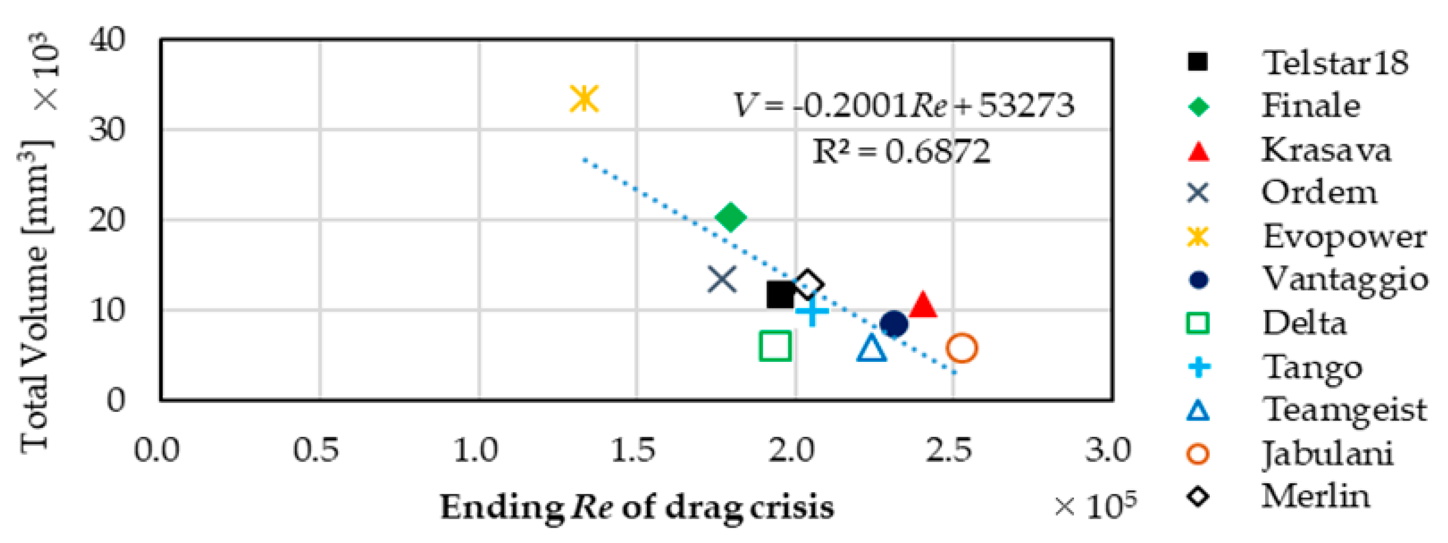
Figure 2a–c show the measurement results of ball groove specification, such as the total groove length, the cross-section of each groove, and total groove volume. Compared to the drag coefficient results, the total groove length was not relevant. However, there was a strong negative correlation between the Starting and the Ending Reynolds number. As shown by the drag crisis tendency of the Jabulani and the Evopower, it was found that the Starting Reynolds number and the Ending Reynolds number decreased as the maximum groove area and total groove volume increased. The correlation coefficient between the total volume and Ending Reynolds number was −0.83, as shown in Figure 3, which shows that the tendency was very strong.

3.3. Oil Film Experiment/2D-PIV Measurement

Figure 4 shows the side view of balls on the oil film results of (a) the Smooth sphere, (b) the Telstar, (c) the Krasava, (d) the Final, and (e) the Vantaggio. The flow flew from left to right and all the balls were conducted in a supercritical region at Re = 4.3 × 10⁵. In the case of a sphere, it had the first and second separation points on the surface. The first separation line showed the line of separation bubble where the laminar boundary layer separated and attached the ball surface. The second one indicated the turbulent separation line, where the flow around the ball separated. There was no such separation pattern in the other balls. All the other balls had only the line of turbulent separation. It was found that each panel groove had such separation bubbles and triggered the transition from laminar to turbulent flow.
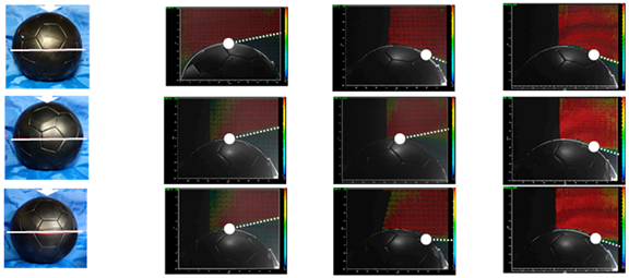
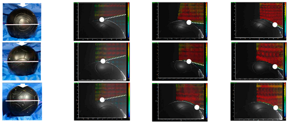
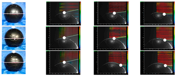
Table 2, Table 3, Table 4 and Table 5 show the 2D-PIV results of the Evopower, the Vantaggio, the Jabulani, and the TeamGeist, respectively. The separation point and the wake direction are indicated in each figure. In all cases of the subcritical and supercritical regions of drag crisis, it could be seen that the position of the separation point and the flow direction of the wake flow were the same despite the change in the panel orientation. In the subcritical state of drag crisis in Table 2, Table 3, Table 4 and Table 5, where Re was less than 1.8 × 10⁵ (as shown in Figure 3), the flow separation occurred around 90° when the center of the left front of the ball was defined as 0°. The CD in this state was about 0.5 in the Reynolds number, less than 1.0 × 10⁵ in Figure 3a. This was because the width of the turbulent ball wake became large on account of the separation occurred at around 90°. However, the separation point occurred in more than 90° in the supercritical state in Table 2, Table 3, Table 4 and Table 5, and the CD became smaller to about 0.2 in the Reynolds number, more than 2.5 × 10⁵ in Figure 4. This was because as the Reynolds number increased the ball grooves stimulated the boundary layer, and the turbulent boundary layer, which was strong against flow separation, was created. Therefore, the flow separation was delayed, resulting in a narrow wake turbulence width. Comparing this with the results of the oil film experiment in Figure 4, the position of the separation point of 2D-PIV coincided with the separation line of the oil film method in the supercritical region.
In the drag crisis state, the position of the separation point and the flow expansion direction of the wake varied depending on the orientation of the panel in any ball. Accordingly, it was found that the laminar separation and the turbulent separation were mixed depending on the panel in the drag crisis state, and the flow around the ball was partially different. This is the reason for the difference in aspects of the drag crisis depending upon the ball panels.
To confirm these facts, compared to the same Re range of 8 m/s for the Evopower shown in Table 2 and 9 m/s for the Vantaggio indicated in Table 3, the CD diagram in Figure 4 demonstrates that the Evopower was in the range of the drag crisis and the Vantaggio was in the subcritical region. The separation points of different ball orientations for the Evopower were partially different in the critical state, as shown in Table 2. But the separation points of different orientations were constant in the subcritical state of the Vantaggio, as shown in Table 3. Accordingly, the cause of the difference in the aspect of the drag crisis against Re was thought to the panel groove in which laminar and turbulent regions were mixed. Concerning the critical states of the Jabulani, as shown in Table 4, and the TeamGeist, as shown in Table 5, the boundary layer was separated earlier around 90° on the smooth surface without grooves. However, the flow separation point moved backward after passing through a groove between smooth panels. The ball groove is thought to be a promotor of turbulence.

4. Conclusions

In order to confirm the relationship between the aerodynamic characteristics of soccer balls and their panels, the fluid force experiment, groove shape measurement, oil film experiment, and 2D-PIV measurement were conducted. The following results were obtained:
  • The CD diagrams and also the aspects of the drag crisis were different from the panel shape.
  • The total volume of the groove affects the Reynolds number at which the drag crisis occurs. The panel groove affects the shape of the drag crisis.
  • The position of the flow separation point did not change in the subcritical and supercritical regions by the ball orientation.
  • The aspect change of the drag crisis in panel difference causes the panel groove mixed with laminar and turbulent regions.

References

  1. Passmore, M.; Rogers, D.; Tuplin, S.; Harland, A.; Lucas, T.; Holmes, C. The aerodynamic performance of a range of FIFA-approved footballs. J. Sports Eng. Technol. 2012, 226, 61–70. [Google Scholar] [CrossRef]
  2. Goff, J.E.; Asai, T.; Hong, S. A comparison of Jabulani and Brazuca non-spin aerodynamics. J. Sports Eng. Technol. 2014, 228, 188–194. [Google Scholar] [CrossRef]
  3. Goff, J.E.; Hong, S.; Asai, T. Aerodynamic and surface comparisons between Telstar 18 and Brazuca. J. Sports Eng. Technol. 2018, 232, 342–348. [Google Scholar] [CrossRef]
  4. Hong, S.; Asai, T.; Seo, K. Flow Visualization around Panel Shapes of Soccer Ball. Procedia Eng. 2015, 112, 391–394. [Google Scholar] [CrossRef]
  5. Hong, S.; Asai, T.; Seo, K. Visualization of air flow around soccer ball using a particle image velocimetry. Sci. Rep. 2015, 5, 15108. [Google Scholar] [CrossRef] [PubMed]
  6. Murakami, M.; Kondoh, M.; Iwai, Y.; Seo, K. Measurement of aerodynamic forces and flow field of a soccer ball in a wind tunnel for knuckle effect. Procedia Eng. 2010, 2, 2467–2472. [Google Scholar] [CrossRef]
Figure 1. The coefficient of drag (CD) diagram of each ball.
Proceedings 49 00117 g001
Figure 2. Specifications of ball groove.
Proceedings 49 00117 g002
Figure 3. The relation between the Ending Re of drag crisis and total groove volume.
Proceedings 49 00117 g003
Figure 4. The results of the oil film experiment to grasp the separation point on the panels.
Proceedings 49 00117 g004
Table 1. Balls used in the experiment and the experiment items.
NameMerlinTelstar18KrasavaOrdemFinaleVantaggio
Design Proceedings 49 00117 i001 Proceedings 49 00117 i002 Proceedings 49 00117 i003 Proceedings 49 00117 i004 Proceedings 49 00117 i005 Proceedings 49 00117 i006
Exp.Fluid forcedonedonedonedonedonedone
Oil film donedone donedone
PIV donedone
NameEvopowerDeltaTang12JabulaniTeamGeist
Design Proceedings 49 00117 i007 Proceedings 49 00117 i008 Proceedings 49 00117 i009 Proceedings 49 00117 i010 Proceedings 49 00117 i011
Exp.Fluid forcedonedonedonedonedone
Oil film
PIVdone donedone
Table 2. The PIV Results of the Evopower with different panel orientations and different flow aspects.
No.Panel Orientation
and Laser Position
Subcritical (5 m/s)
Re = 7.3 × 10⁴
Critical (8 m/s)
Re = 1.2 × 10⁵
Supercritical (15 m/s)
Re = 2.2 × 10⁵
a Proceedings 49 00117 i012
b
c
Table 3. The PIV results of the Vantaggio with different panel orientations and different flow aspects.
No.Panel Orientation
and Laser Position
Subcritical (9 m/s)
Re = 1.3 × 10⁵
Critical (12.5 m/s)
Re = 1.8 × 10⁵
Supercritical (20 m/s)
Re = 2.9 × 10⁵
a Proceedings 49 00117 i013
b
c
Table 4. The PIV results of the Jabulani with different panel orientations and different flow aspects.
No.Panel Orientation
and Laser Position
Subcritical (5 m/s)
Re = 7.3 × 10⁴
Critical (14 m/s)
Re = 2.1 × 10⁵
Supercritical (20 m/s)
Re = 2.9 × 10⁵
a Proceedings 49 00117 i014
b
c
Table 5. The PIV results of the TeamGeist with different panel orientations and different flow aspects.
No.Panel Orientation
and Laser Position
Subcritical (5 m/s)
Re = 7.3 × 10⁴
Critical (12.5 m/s)
Re = 1.8 × 10⁵
Supercritical (20 m/s)
Re = 2.1 × 10⁵
a Proceedings 49 00117 i015
b
c