1. Introduction
Thoracic and pelvic tilt changes step to step during maximal accelerated sprinting [
1]. The pelvic orientation during sprinting influences the power generation applied onto the ground [
2], and thus is important to consider for coaches. Motion capture systems (mocap) are typically considered a gold standard method for accurate human kinematic monitoring and have been previously utilised for sprinting research [
2]. However, mocap is expensive, has high expertise requirements, is usually limited to laboratory environments and typically has only been used to measure sprinting over a short distance [
2,
3,
4,
5]. In sprint events, sprinters run on both straight and curved tracks, except short distance events such as the 100 m. Previous studies showed differences in sprinter’s kinematics between straight and curved sprinting [
6,
7], but it was difficult for mocap to measure continuous changes in kinematics over the entire race.
Wearable sensors including inertial measurement units (IMUs) allow in field monitoring and may overcome the practical limitations of mocap, while remaining comparable in accuracy for monitoring sprint kinematics. IMUs have been used for sprinting studies to estimate temporal parameters [
8], stance duration [
9] and sprint velocity [
10], demonstrating that IMUs can be used to monitor sprinting in the field. Bergamini et al. [
11] measured sprinter’s trunk inclination using a lower back-mounted IMU and reported valid angular displacements and angular velocity in the sagittal plane during the sprint start phase. However, it has not been elucidated whether IMUs are also valid for the measurement of curved sprinting and angular displacements in the coronal or transverse plane.
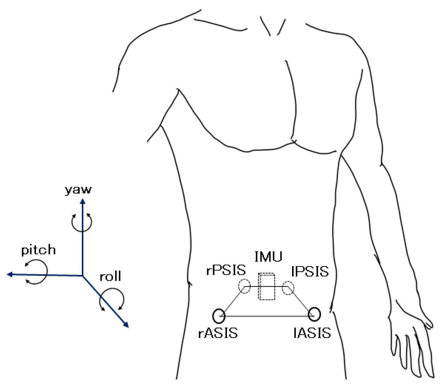
The purpose of this study was to elucidate pelvic orientation angles including pelvic obliquity in the coronal plane (roll), anterior–posterior tilt in the sagittal plane (pitch) and rotation in the transverse plane (yaw) using a single lower back-mounted inertial sensor during sprinting. To this end, sprint runs were performed on an indoor track and an outdoor 400 m track by collegiate male sprinters. The IMU data obtained from the indoor track trials were compared with mocap data to determine the absolute angle errors of using a single IMU for pelvic orientation monitoring.
2. Materials and Methods
A DSP wireless 9 axis motion sensor (Sports Sensing, Fukuoka, Japan) was used as the IMU in this study. This unit has a tri-axial accelerometer, a gyroscope and a magnetometer, with dimensions 53 mm × 38 mm × 11 mm (H × W × D) and a weight of 32 g. One sensor was attached with thin double-sided tape above the participant’s L5 spinous process and overlapped with a plastic surgical tape and covered with form-fitting sprint pants. The sensor range was ±16 G and ±1500 dps and the sampling rate was 200 Hz with 16-bit resolutions. The sensor started recording after it was attached to a participant and continued until all trials were finished. To synchronise with mocap, a DSP wireless analogue signal logger (Sports Sensing, Fukuoka, Japan) was used to record triggers pulled at the start of sprint trials. The orientation angles of the sensor were derived with Madgwick’s previously validated open-sourced AHRS implementation for an IMU [
12]. This algorithm is computationally inexpensive but as accurate as the Kalman-based algorithm. It achieved a static root mean square (RMS) error of <0.8° and a dynamic RMS error of <1.7° [
12]. In this research, only angular velocity and acceleration were used for angle estimation, and its parameter β was set to 0.03.
A mocap setup with twenty-eight infrared cameras (Raptor-E, Motion Analysis, CA, USA) was used as a reference system. The sampling frequency was 250 Hz for the recording, and it was resampled to 200 Hz for further processing. Cameras were arranged around an indoor sprint track and captured participant’s pelvic movement from approximately 30 to 45 m from the start line. To observe the difference between straight sprinting and entering to the bend section, a bend track (radius 38.2 m) was set at a 40 m position for the bend sprint tests. Full body marker sets were used to observe sprint technique. Coordinates of markers including the right and left anterior superior (ASIS) and posterior superior (PSIS) iliac spines were used to calculate pelvic movements (
Figure 1).
Pelvic orientation angles from the mocap were calculated with four markers according to previous studies [
1,
13,
14]. Pelvic obliquity (roll) and rotation (yaw) were calculated as tilts of left and right ASIS markers towards the horizontal line and the runway. Anterior–posterior tilt (pitch) was obtained as an angle formed by a vertical plane and the plane defined by ASIS markers and a middle point between the two PSIS markers. Analogue triggers at the start of trials were recorded by the mocap and used for data synchronisation.
Participants were instructed to stand in an upright anatomical position prior to data capture, used for IMU data calibration for the pitch and roll. In this research, magnetometer data were not employed to calculate angles, and thus absolute heading angle (yaw) could not be obtained for the sensor. Therefore, the sensor yaw angle was offset with the first angle obtained from the mocap for each trial.
Eight collegiate male sprinters (age: 20.9 ± 0.8 year; mass 66.2 ± 4.2 kg; stature: 171.6 ± 3.5 cm) participated in the indoor trials. Each participant performed two 50 m straight sprints and two 44 m sprints that started on the straight track and transitioned into a bend sprint. The participants started from a crouched starting position for each trial and sprinted through a 15 m capture area of mocap. Additionally, outdoor 200 m maximal sprint trials were carried out by three participants to confirm the effectiveness of the method in a practical sprint distance and environment including a curved path.
3. Results
3.1. Comparison with Motion Capture System
Sixteen straight sprint data and sixteen entering the bend sprint data were collected by indoor tests.
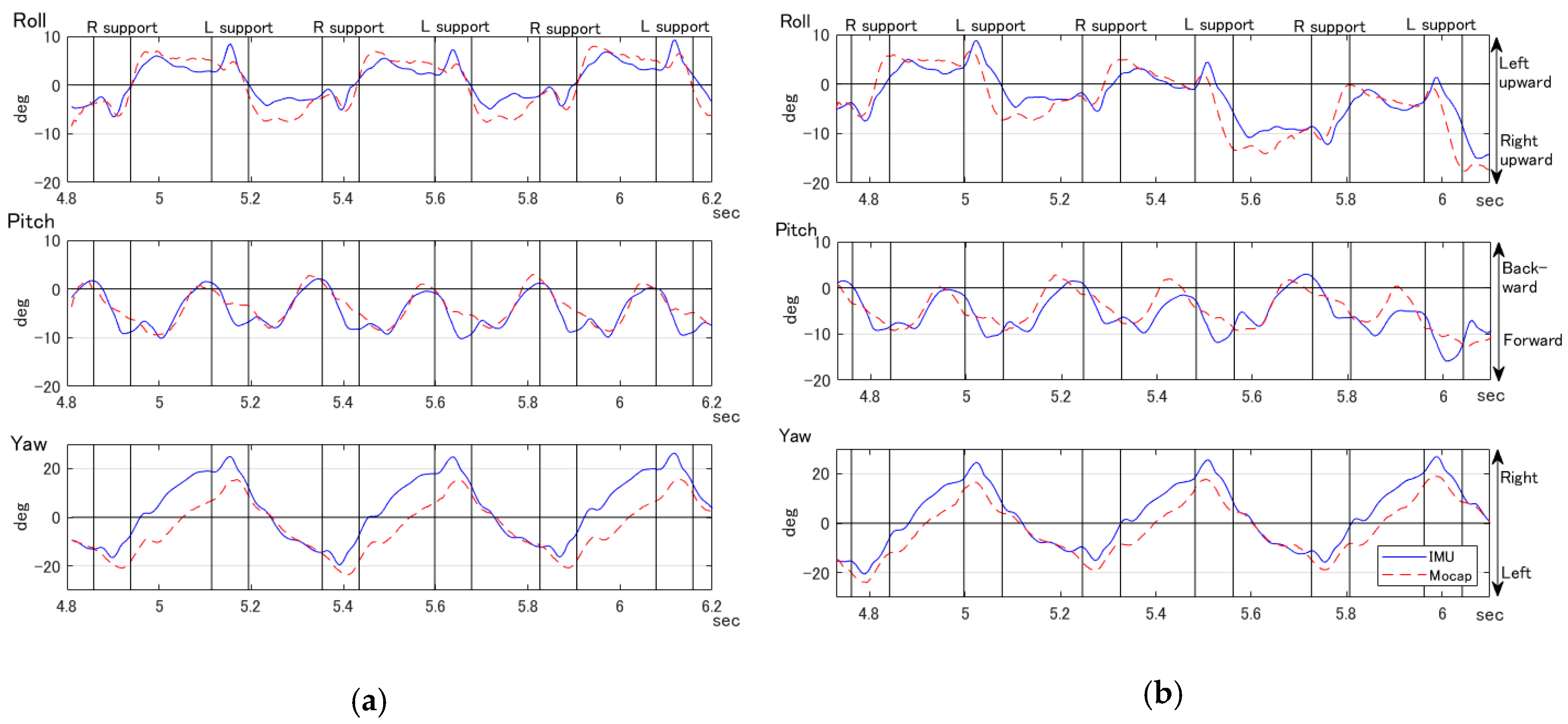
Figure 2 shows a representative sample of pelvic tilts (roll, pitch and yaw) from one participant estimated by the IMU and calculated from mocap data. Support phase durations of each leg are shown with vertical lines for reference. Support phase durations were manually retrieved from the observation of full body markers of the mocap.
To assess the IMU accuracy compared to mocap, the root mean squared error (RMSE) and a Pearson’s correlation coefficient between IMU and mocap were computed for each trial and are shown in
Table 1. The absolute angle RMSE between the IMU and mocap was 4.1° for roll, 2.8° for pitch and 3.6° for yaw for all trials. Pearson’s correlation coefficients were 0.88 for roll, 0.79 for pitch and 0.97 for yaw, demonstrating strong linear relationships for all pelvic tilt angles.
3.2. Two-Hundred Metre Sprint Measurements with a Single IMU
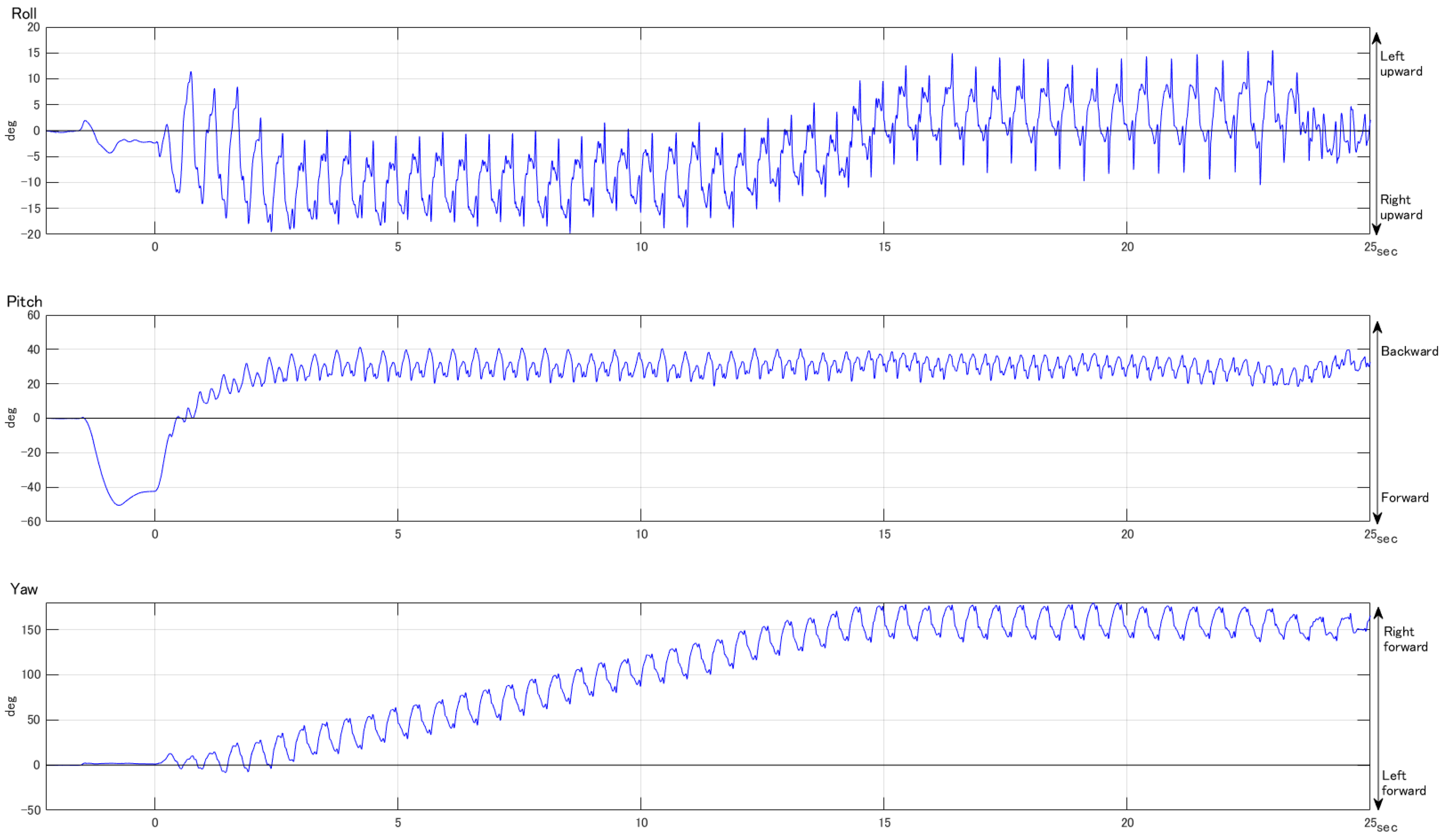
Figure 3 shows a representative sample of pelvic angles for a 200 m sprint in lane four of an outdoor athletic track (radius 41.8 m). In this figure, orientation angles were set to zero at the sprinter’s stable pose after the “on your marks” call. The start time (t = 0) was manually chosen from the data and the data include both before and after sprinting.
4. Discussion
The indoor test results demonstrate accuracy of less than five degrees of RMSE compared to mocap for all pelvic angles. There were small differences between the types of trials (straight and entering into bend). This level of accuracy is sufficient for monitoring pelvic angles for coaches to judge the influence of technique during maximal sprinting.
In the test, mocap tracked four markers attached around the pelvis according to previous studies [
1,
13,
14]. Therefore, the IMU data were compared with quasi-pelvic movement as reported in previous studies, not with the device’s housing angles measured by mocap with device attached markers. The notable finding of the presented method is that a single IMU may be used to estimate detailed pelvic movement which was previously measured with a four maker mocap setup during sprinting.
Some differences between pelvic angles measured using IMU and mocap were also found. For example, on pitch angles, small peaks occurred after toe-off in IMU data but not for mocap. This difference may be derived from the methods of calculating angles and/or the motion artefacts of the skin-mounted sensor. However, on a broader basis, the angles estimated by an IMU had minimal differences for assessing pelvic movements during sprinting. It was observed that the roll and yaw angles periodically change in two steps, and pitch angles periodically change in a step. Roll angles decreased (to right upward) at the beginning of the right leg support phase, and started to increase (to left upward) at end of the right leg support phase. Inverse angle changes were observed at the left leg support phase. Pitch angles decreased (lean forward) during right and left leg stance phases and increased (lean backward) during the flight phases. Yaw angles changed direction during right and left support phases. In the tests, the 19th to 25th steps were captured by mocap at around 30 to 45 m from the start line. The amplitude of these steps for straight sprints almost matched with the amplitude during the comparable section reported by a previous study [
1].
In
Figure 2, the difference between straight sprinting and transitioning into the bend section was observed in roll and pitch angles. In
Figure 2b, the bend section started before the last left leg contact (around 5.9 s). The roll angle started rotating toward the right upward two steps before the bend section (around 5.5 s). Clear understanding for bend sprinting has yet to be established but the use of IMUs may contribute toward future research.
During the field measurements (200 m sprints), all pelvic angle transitions showed consistent results, as demonstrated in
Figure 3. The transition of pelvic angles shows reasonable vibration and it was observed that the amplitude and waveform were similar to the indoor tests. Therefore, it was assumed that the results during the measured 15 m capture length (indoor trials) of mocap data are translatable to practical conditions. However, there were several raw acceleration data in excess of the measurable limits. These happened in a very short time (only one sample at a time) and did not appear to influence the estimation of angles, but it should be considered in detail in the future.
5. Conclusions
It was confirmed that a single inertial sensor is now supported as a valid tool to measure movements of the pelvis during sprinting. The strength of IMU devices is that they are commercially available and affordable, have comparable accuracy to mocap and overcome the practical limitations of mocap systems. More practical mounting includes wearing a single sensor in worn garments during sprinting, opposed to being applied with tape on the skin. This may be more practical for field use and eliminate expertise requirements for anatomical mark up; however, it may present greater errors due to movement of the worn garments and no expertise for mark up. This may be an area for future investigation. In addition, this research supports the use of the presented method for future sprint research designs. Paired with simple user-friendly graphical user interfaces, these devices may have significant practical applications for coaches to provide real time feedback for athletes.


