Proceeding Paper

Shear-Thinning Fluid Flow in Variable-Aperture Channels †

by
Alessandro Lenci
and
Vittorio Di Federico
*
Dipartimento di Ingegneria Civile, Chimica, Ambientale e dei Materiali (DICAM), Università di Bologna Alma Mater Studiorum, 40136 Bologna, Italy
*
Author to whom correspondence should be addressed.
Presented at the 4th International Electronic Conference on Water Sciences, 13–29 November 2019; Available online: https://ecws-4.sciforum.net/.
Proceedings 2020, 48(1), 28; https://doi.org/10.3390/ECWS-4-06426
Published: 12 November 2019
(This article belongs to the Proceedings of The 4th International Electronic Conference on Water Sciences)

Abstract

:
Non-Newtonian fluid flow in a single fracture is a 3D nonlinear phenomenon that is often averaged across the fracture aperture and described as 2D. To capture key interactions between fluid rheology and spatial heterogeneity, we adopted a simplified geometric model to describe aperture variability, consisting of adjacent one-dimensional channels with constant aperture, each drawn from assigned aperture distribution. The flow rate was then derived under the lubrication approximation for the two limiting cases of an external pressure gradient that was parallel/perpendicular to the channels; these two arrangements provided an upper/lower bound to fracture conductance. Fluid rheology was described via the Prandtl–Eyring shear-thinning model. Novel closed-form results for flow rate and hydraulic aperture were derived and are discussed; different combinations of parameters describing the fluid rheology and variability of the aperture field were considered. In general, flow rate depends, in a nonlinear fashion, on the dimensionless pressure gradient and distribution parameters.

Published: 12 November 2019

1. Introduction

Non-Newtonian fluid flow in fractured media is of interest in many environmental applications, such as hydraulic fracturing, drilling operations, enhanced oil recovery, and subsurface contamination and remediation. The basic building block in fractured-medium modeling is a thorough understanding of flow and transport in a single fracture [1]. A key concept in single-fracture flow and transport is the fracture aperture, defined by the space between fracture walls. Due to the heterogeneity of these surfaces, the fracture aperture is spatially variable [2,3]. Flow modeling at the single-fracture scale leads to the determination of flow rate under a given pressure gradient as a function of parameters describing the variability of the aperture field or of the confining walls. A hydraulic aperture can then be derived from the flow rate [4] as the aperture of a smooth-walled conduit that would produce the same flow rate under a given pressure gradient as the real rough-walled fracture.
When fluid behavior is non-Newtonian, the effects of spatial variability are compounded with the influence of rheology, producing striking results such as pronounced channeling effects [5]. Different constitutive equations were used to represent non-Newtonian behavior in fracture flow [5,6]. A comprehensive comparison of results for different constitutive equations is still lacking, but the impact of fluid rheology is likely to be significant.
Detailed 2D or 3D flow modeling of non-Newtonian flow in single fractures needs to be numerically tackled, with considerable computational effort given flow nonlinearity. Not surprisingly, some authors pursued a simpler approach with the aim of providing order-of-magnitude estimates and reference benchmarks for fracture conductivity. Basically, this approach considers a simplified, extremely anisotropic fracture geometry, with an aperture variable along one direction, and constant aperture channels along the other. The arbitrary orientation of the external pressure gradient with respect to the channels gives rise to two limit cases: (i) parallel arrangement, which provides an upper bound to the conductivity; and (ii) serial arrangement, which provides a lower bound. Flow in an isotropic aperture field is then addressed considering the fracture as a random mixture of elements in which the fluid flows either transversal or parallel to the aperture variation. The hydraulic aperture is derived by a suitable averaging procedure [7].
The present paper follows this avenue of research exploring the impact of a classical, two-parameter shear-thinning constitutive equation, the Prandtl–Eyring model [8], which overcomes the unrealistic behavior of the power-law model, having infinite apparent viscosity for zero shear rate. Section 2 derives the flow rate under an assigned external pressure gradient for flow of a Prandtl–Eyring fluid in a parallel-plate fracture. Section 3 presents the adopted simplified geometry, derives general expressions of the flow rate for flow parallel or perpendicular to constant aperture channels, and proposes a method to evaluate the hydraulic aperture for the 2D case. Section 4 introduces a specific probability-distribution function for the aperture, the gamma distribution, and illustrates corresponding results for flow rate and hydraulic aperture.

2. Prandtl–Eyring Fluid Flow in Constant-Aperture Fracture

We considered the flow of a non-Newtonian Prandtl–Eyring fluid between two smooth parallel plates separated by a distance b (fracture aperture); the co-ordinate system is shown in Figure 1. Uniform pressure gradient P x ¯ = d P / d x was applied in the x direction, where P = p + ρ g z includes gravity effects, p is pressure, g gravity, and ρ fluid density. Assuming flow in the x direction, velocity v x is solely a function of z . Momentum balance yields linear shear-stress profile
z x = P x ¯ z .
A Prandtl–Eyring fluid is rheologically described in simple shear flow by [8]
τ z x = A sinh 1 1 B d v x d z ,
where τ z x is shear stress, d v x / d z = γ ˙ shear rate, and parameters A , B describe the fluid. Figure 2 shows apparent viscosity η γ ˙ , defined by relationship τ z x = η γ ˙ γ ˙ , as a function of shear rate γ ˙ for realistic parameter values.
Substituting Equation (2) in Equation (1), and integrating with the no-slip condition at wall v x b / 2 = 0 , gives the velocity profile between z = b / 2 and z = + b / 2 as
v x z = A B P x ¯ cosh P x ¯ b 2 A cosh P x ¯ z 2 A .
Total flow rate Q x through the fracture for width W in the y direction perpendicular to the pressure gradient was derived integrating Equation (2); the result was
Q x = A B W P x ¯ b cosh P x ¯ b 2 A 2 A P x ¯ sinh P x ¯ b 2 A ;   q x = Q x W ;   V x = q x b ,  
where q x is the flow rate per unit width, and V x the average velocity.
If the aperture varies, as in real rock fractures, a flow law of the type of Equation (4) is valid, replacing constant aperture b with hydraulic aperture b H , accounting for the aperture variation [7,9].

3. Flow in Variable-Aperture Channels

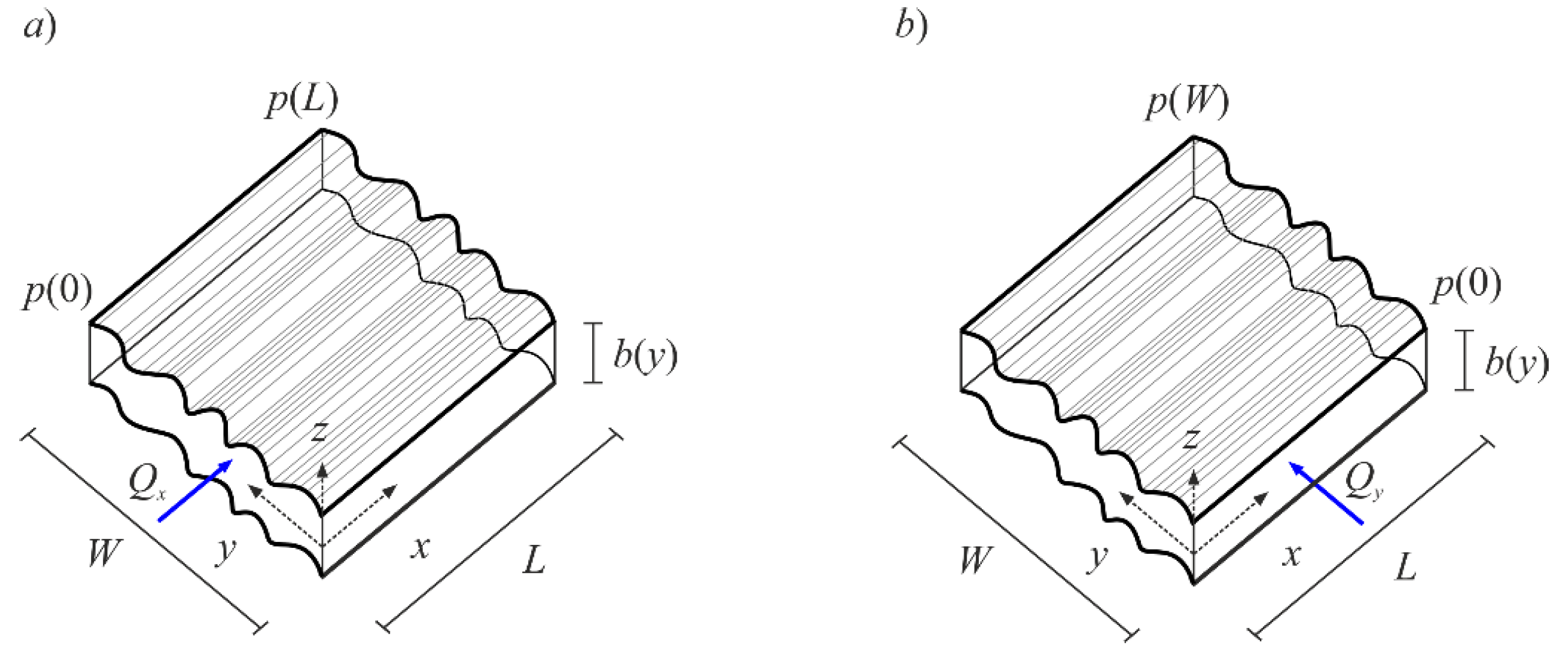
Flow and transport simulations in variable-aperture fractures typically consider aperture b x , y to vary as a two-dimensional, spatially homogeneous, and correlated random field with probability density function f b and assigned statistics. Fracture dimensions were assumed to be much larger than the integral scale of the aperture autocovariance function; then, under ergodicity, spatial and ensemble averages were interchangeable, and a single realization could be examined [4]. This approach was adopted by [10,11] to study the flow of power-law and truncated-power-law fluids in simplified aperture fields, where the aperture varied only along one spatial co-ordinate, and the external pressure gradient, hence the flow, was either transverse or parallel to the aperture variability; such an idealized fracture of dimensions L and W is shown in Figure 3.

3.1. Channels in Parallel

Consider flow along direction x parallel to constant-aperture channels, and driven by external pressure gradient P x ¯ . To obtain the volumetric flux, a procedure similar to that adopted in [12] was used. The fracture was discretized into N neighboring parallel channels, each having equal width W i = W / N , length L , and constant aperture b i . Assuming that the shear between neighboring channels and the drag against the connecting walls could be neglected, the flow rate in each channel of the constant aperture along x is given by Equation (4), with b i in place of b and W i in place of W . Hence, summing over all channels, total flow rate in the fracture was
Q x = i = 1 N Q x i = A B W P x ¯ 1 N i = 1 N b i c o s h P x ¯ b i 2 A 2 A P x ¯ s i n h P x ¯ b i 2 A .
Taking the limit as N , the width of each channel tended to zero and the discrete aperture variation to a continuous one; then, under ergodicity, Equation (5), for the flow rate per unit width, gives expression
q x = Q x W = A B P x ¯ 0 b c o s h P x ¯ b 2 A f b d b 2 A P x ¯ 0 s i n h P x ¯ b 2 A f b d b ,
where f b is the probability-distribution function of aperture field b , defined between 0 and . Finally, hydraulic aperture b H x may be numerically derived upon equating q x from Equation (6) with Equation (4), written with b H x in place of b .

3.2. Channels in Series

Consider flow along direction y parallel to constant-aperture channels, and driven by external pressure gradient P y ¯ . The fracture, having length W and width L , was discretized into N cells in series of equal length W i = W / N , each of width L and constant aperture b i . As volumetric flux Q y through each cell was the same, so was the flow rate per unit width in each cell, i.e., q y i = q y = Q y / L . Total pressure loss along the fracture in the y direction, Δ P , equaled the sum of pressure losses in each cell, Δ P i , i.e., Δ P = i = 1 N Δ P i , neglecting pressure losses due to the succession of constrictions and enlargements. This, in turn, yielded external mean pressure gradient P y ¯ as P y ¯ = 1 N i = 1 N P yi , where the pressure gradient in each cell of constant aperture b i was given by P y i = P y i q y , b i , A , B , obtained by deriving the pressure gradient as a function of flow rate from Equation (4), written replacing subscript x with y and b with b i . Taking the limit as N , the length of each cell tended to zero, and the discrete aperture variation to a continuous one; then, under ergodicity, the previous relationship gives, for the mean pressure gradient in the y direction,
P y ¯ = 0 P y q y , b , A , B f b d b .
The integration of Equation (7) gives the flow rate as q y = q y P y ¯ , A , B ,   f b . Lastly, hydraulic aperture b H y was derived upon equating q y thus derived with Equation (4), written with subscript y in place of x and with b H y in place of b .

3.3. Flow in 2D Isotropic Aperture Field

Non-Newtonian flow in a fracture characterized by an isotropic, two-dimensional aperture variation is highly complex [6], and the hydraulic aperture can only be obtained by means of numerical simulations. However, it can be argued [12] that the scheme with channels in parallel is an upper bound to the hydraulic aperture for the general 2D case, while the scheme with channels in series provides a lower bound, in analogy to hydraulic conductivity [13]. If the fracture is seen as a random mixture of elements where the fluid flows either transversal or parallel to aperture variation, flow can be approximated by a suitable average of these flows; ergodicity ensures that boundary effects are negligible [4]. Hydraulic-aperture values derived for the two schemes significantly differed; hence, following the procedure adopted by, e.g., [4,7,9,10,11,12], an estimate of the hydraulic aperture was derived as the geometric mean of the hydraulic apertures for the parallel and serial arrangement as b H = b H x b H y .

4. Estimate of Hydraulic Aperture

4.1. Aperture-Probability Distribution

Gamma distribution of shape parameter d and scale parameter b g , entailing non-negative apertures, was adopted to quantify the previous general expressions, consistently with earlier work [11]. Its probability-density function, expected value, variance, and skewness are given by
f b = 1 Γ d b d 1 b g d e b / b g ;   b = d b g ; σ b 2 = d b g 2 = b 2 d ,   γ b = 2 d ,
where Γ Δ is the gamma function.
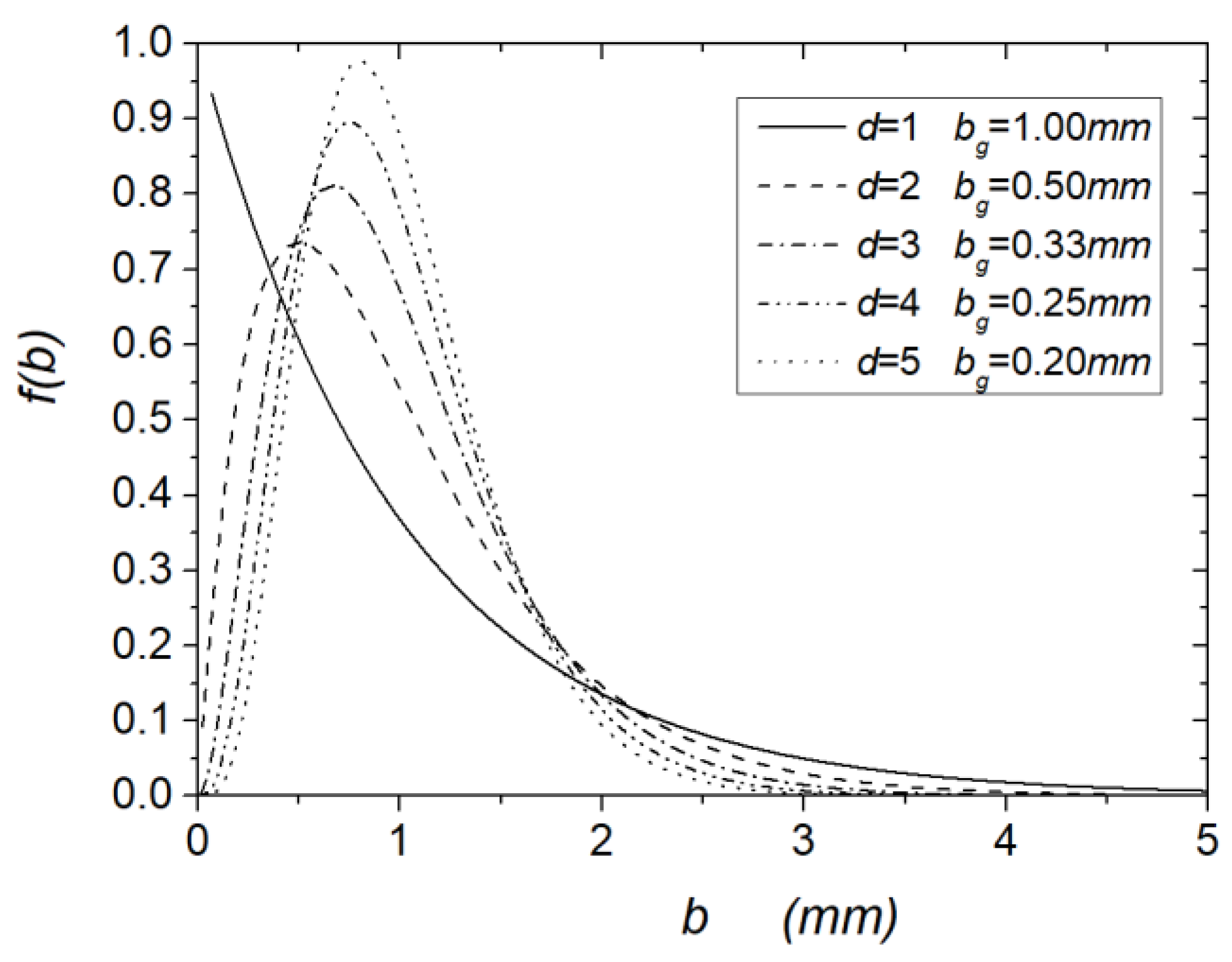
Gamma distribution is illustrated in Figure 4; for d = 1 , it reduced to exponential distribution, with maximal skewness; as d , gamma distribution tended to normal distribution with the same mean and variance, and zero skewness.

4.2. Channels in Parallel

Inserting the Equation (8) in Equation (6) after integration [14] (p. 403), some algebraic manipulations, and exploiting the properties of the gamma function, gives the result
q x = A B b P ¯ x q x D ;   q x D = 1 2 Ω d + 1 u 1 1 u d + 1 + d + 1 u + 1 1 + u d + 1 ,
where
Ω = P x ¯ b 2 A = τ w A ;   u = Ω d ;   u < 1 .
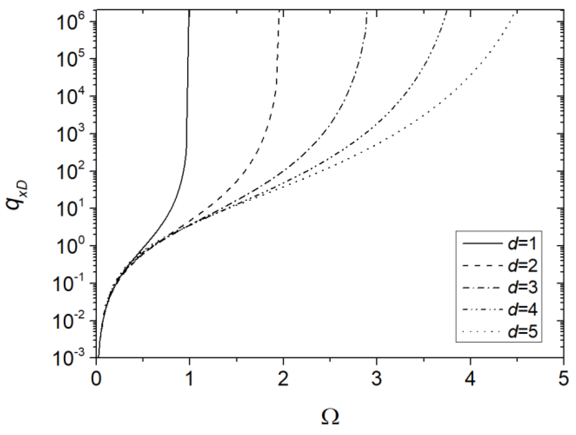
Equation (10) established that the ratio between shear stress τ w at the wall of a parallel plate fracture of aperture b and shear stress A describing the fluid cannot exceed shape parameter d of the distribution. Figure 5 shows the dimensionless flow rate per unit width q x D as a function of Ω for different values of d . As Ω 0 + , the flowrate tended to ; such negative values are not realistic. On the other hand, for Ω d , the flowrate tended to infinity, and curves showed a vertical asymptote of equation Ω = d . For low values of Ω , the curves tended to overlap regardless of the value of d . Flow rate strongly depended on the dimensionless pressure gradient and the distribution parameters.
The hydraulic aperture for parallel arrangement b H x was obtained by solving the following implicit equation in unknown r x :
r x cosh r x Ω 1 Ω sinh r x Ω = 1 2 Ω d + 1 u 1 1 u d + 1 + d + 1 u + 1 1 + u d + 1 ; r x = b H x b .
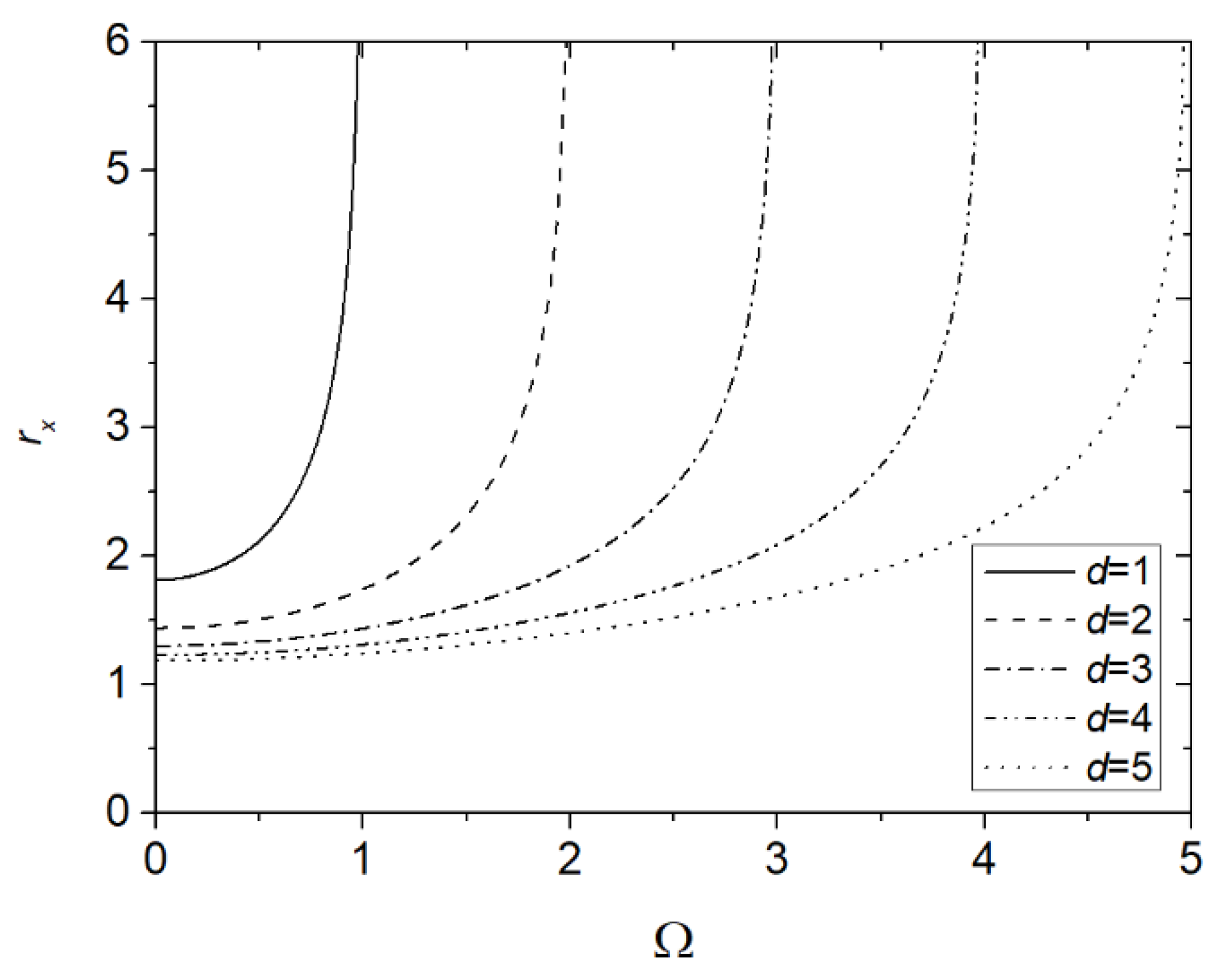
Figure 6 illustrates ratio r x defined by Equation (11) as a function of Ω for different values of d . Ratio r x strongly increased with Ω , more so for lower values of d , i.e., more skewed distribution. The curves showed a vertical asymptote when dimensionless pressure gradient Ω approached d . For low values of Ω , the curves were almost horizontal.

Acknowledgments

Vittorio Di Federico gratefully acknowledges the financial support from Università di Bologna Almaidea 2017 Linea Senior Grant.

Conflicts of Interest

The authors declare no conflict of interest. The founding sponsor had no role in the design of the study; in the collection, analyses, or interpretation of data; in the writing of the manuscript, and in the decision to publish the results.

References

  1. Adler:, P.M.; Thovert, J.F.; Mourzenko, V.M. Fractured Porous Media; Oxford University Press: Oxford, UK, 2002; p. 184. [Google Scholar]
  2. Wang, L.; Cardenas, M.B. Analysis of permeability change in dissolving rough fractures using depth-averaged flow and reactive transport models. Int. J. Greenh. Gas Control 2019, 91, 102824. [Google Scholar] [CrossRef]
  3. Meheust, Y.; Schmittbuhl, J. Geometrical heterogeneities and permeability anisotropy of rock fractures. J. Geophys. Res. 2001, 106, 2089–2102. [Google Scholar] [CrossRef]
  4. Silliman, S. An interpretation of the difference between aperture estimates derived from hydraulic and tracer tests in a single fracture. Water Resour. Res. 1989, 25, 2275–2283. [Google Scholar] [CrossRef]
  5. Lavrov, A. Redirection and channelization of power-law fluid flow in a rough walled fracture. Chem. Eng. Sci. 2013, 99, 81–88. [Google Scholar] [CrossRef]
  6. de Castro, A.R.; Radilla, G. Flow of yield stress and Carreau fluids through rough walled rock fractures: Prediction and experiments. Water Resour. Res. 2017, 53, 6197–6217. [Google Scholar] [CrossRef]
  7. Zimmerman, R.W.; Kumar, S.; Bodvarsson, G.S. Lubrication theory analysis of the permeability of rough-walled fractures. Int. J. Rock Mech. Min. Sci. Geomech. Abstr. 1991, 28, 325–331. [Google Scholar] [CrossRef]
  8. Yoon, H.K.; Ghajar, A.J. A note on the Powell-Eyring fluid model. Int. Commun. Heat Mass 1967, 14, 381–390. [Google Scholar] [CrossRef]
  9. Di Federico, V. Estimates of equivalent aperture for Non-Newtonian flow in a rough-walled fracture. Int. J. Rock Mech. Min. Sci. Geomech. Abstr. 1997, 34, 1133–1137. [Google Scholar] [CrossRef]
  10. Di Federico, V. Non-Newtonian flow in a variable aperture fracture. Transp. Porous Media 1998, 30, 75–86. [Google Scholar] [CrossRef]
  11. Felisa, G.; Lenci, A.; Lauriola, I.; Longo, S.; Di Federico, V. Flow of truncated power-law fluid in fracture channels of variable aperture. Adv. Water Resour. 2018, 122, 317–327. [Google Scholar] [CrossRef]
  12. Zimmerman, R.W.; Bodvarsson, G.S. Hydraulic conductivity of rock fractures. Transp. Porous Media 1996, 23, 1–30. [Google Scholar] [CrossRef]
  13. Dagan, G. Flow and Transport. In Porous Formations; Springer: Berlin/Heidelberg, Germany, 1989; p. 658. [Google Scholar]
  14. Gradshteyn, I.S.; Ryzhik, I.M. Table of Integrals, Series, and Products; Academic Press: New York, NY, USA, 1994; p. 1204. [Google Scholar]
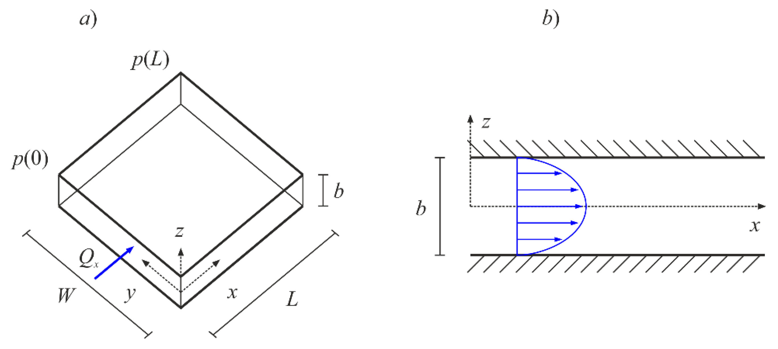
Figure 1. Parallel-plate model. (a) Model representation; (b) cross-sectional velocity profile.
Proceedings 48 00028 g001
Figure 2. Prandlt–Eyring fluid rheology: shear-stress–shear-rate relationship. Rheologic parameters from [7]: A = 0.00452 Pa and B = 0.0301 s−1.
Proceedings 48 00028 g002
Figure 3. Conceptual-model representation. (a) Parallel and (b) serial arrangement.
Proceedings 48 00028 g003
Figure 4. Gamma distribution pdf for different values of rate parameter d , assuming mean fracture aperture b = 1 mm.
Proceedings 48 00028 g004
Figure 5. Dimensionless flowrate per unit width q x D versus dimensionless pressure gradient Ω for different values of distribution parameter d .
Proceedings 48 00028 g005
Figure 6. Ratio r x = b H x / b versus dimensionless pressure gradient Ω for different values of the distribution parameter d.
Proceedings 48 00028 g006
Publisher’s Note: MDPI stays neutral with regard to jurisdictional claims in published maps and institutional affiliations.