Abstract
In most autonomous underwater vehicles (AUVs), the navigation system is based on an inertial navigation system (INS) aided by a Doppler velocity log (DVL). In several INSs, only the velocity vector, provided by the DVL, can be used as input for assistance, thus limiting the integration approach to a loosely coupled one. In situations of partial DVL measurements (such as failure to maintain bottom lock) the DVL cannot provide the AUV velocity vector, and as a result, the navigation solution is based only on the standalone INS solution and will drift in time. To circumvent that problem, the extended loosely coupled (ELC) approach was recently proposed. ELC combines the partial DVL measurements and additional information, such as the pervious navigation solution, to form a calculated velocity measurement to aid the INS. When doing so, the assumption made in the extended Kalman filter (EKF) derivation of zero correlated process and measurement noise covariance does not hold. In this paper, we elaborate the ELC approach by taking into account the cross-covariance matrix of the correlated process (INS) and measurement (Partial DVL) noises. At first, this covariance matrix is evaluated based on the specific assumption used in the ELC approach and then implemented in the EKF algorithm. Using a 6DOF AUV simulation, results show that the proposed methodology improves the performance of the ELC integration approach.
1. Introduction
Most autonomous underwater vehicles (AUVs) are equipped with an inertial navigation system (INS) as their main navigation sensor [1,2]. An INS uses its inertial sensor measurements to provide a complete navigation state that includes the position, velocity and orientation of the platform. Due to measurement noise and biases, the INS navigation solution drifts in time. Therefore, INSs are usually aided by other external sensors or data, such as the Doppler velocity log (DVL) for velocity assistance [3,4].
There are two main approaches for sensor fusion between INS and DVL (also valid for other sensors): (1) loosely coupled (LC); and (2) tightly coupled (TC) [5,6]. In the LC approach, the DVL raw data (relative velocity in each beam direction) is used to calculate the vehicle velocity, which in turn is used to aid the INS via a navigation filter. The advantage of this method is the simplicity of integration and the ability to combine any off-the-shelf INS with any DVL. The main drawback, however, is the requirement for the DVL to operate in bottom lock, which refers to the condition when a sufficient number of beam measurements (at least three) are available. In the TC approach, the DVL raw data is directly used in the navigation filter. Therefore, there is no need for a bottom lock requirement, and aiding may be applied even with a single beam measurement.
In practice, many off-the-self INSs can only receive an external velocity vector measurement from the DVL [7], enabling implementation of the LC approach only. In some situations, such as operation in close proximity to the seafloor, or when experiencing extreme tilt angle beam malfunction, one or more of the DVL beams may not provide the reflection required for determining velocity, thus disabling the DVL’s ability to provide velocity updates to the INS. As a consequence, the INS navigation solution will drift in time.
To circumvent this problem, the extended loosely coupled (ELC) approach for calculating platform velocity with partial DVL measurements was recently proposed [8]. There, the basic idea was to use the partial measured raw data from the DVL combined with additional information to derive the platform velocity vector. This calculated vehicle velocity is used for aiding the INS, as in the regular LC approach. Calculation of the velocity vector in that manner violates one of the assumptions made in the extended Kalman filter (EKF) derivation of the process and measurement noises being uncorrelated.
In this paper, we elaborate the ELC approach by taking into account the cross-covariance matrix of the correlated process (INS) and measurement (Partial DVL) noises. At first, the covariance matrix is evaluated based on the specific assumption used in the ELC approach and then implemented in the EKF algorithm. Using a 6DOF AUV simulation, the results show that the proposed methodology improves the performance of the ELC integration approach.
2. Extended Kalman Filter with Correlated Process and Measurement Noise
Consider the nonlinear system
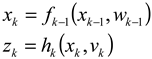 where the system equation f(∙) and measurement equation h(∙) are nonlinear functions, x is the state vector and k is the time-step index. The assumptions on the system and measurement noises are
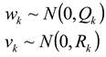 where w is a zero-mean white Gaussian noise with covariance Q and v is a zero mean white Gaussian noise with covariance R. Assuming no correlation between the process and measurement noise, an error-state implementation of a discrete EKF is given by [9]:
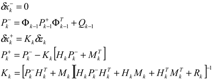
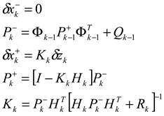 where
where  is the a priori estimate of the error-state vector, δz is the measurement residual vector,
  is the a posteriori estimate of the error state vector,
  is the covariance matrix of the prior estimation error, Kk is the Kalman gain, Hk is the measurement matrix and Φk is the state transition matrix.
is the a priori estimate of the error-state vector, δz is the measurement residual vector, is the a posteriori estimate of the error state vector, is the covariance matrix of the prior estimation error, Kk is the Kalman gain, Hk is the measurement matrix and Φk is the state transition matrix.When the process and measurement noises are correlated, their cross-covariance matrix Mk [10],
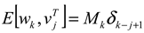 must be taken into account in the EKF algorithm (3). Notice in (4), the process noise at time k is correlated with the measurement noise at time k + 1. The reason is that wk affects the state at time k + 1 just as vk−1 affects the measurement at time k + 1 (see (1) for the definition of the nonlinear system).
When considering the process and measurement noise cross-covariance matrix, the EKF algorithm (3) is modified to [10]
3. Extended Loosely Coupled Approach
The ELC approach is considered herein for INS/DVL fusion with partial DVL measurements; in particular, situations when only two beam measurements are available. In such situations, the velocity vector of the platform cannot be calculated by the DVL, and hence no velocity assistance can be provided to the INS. The ELC approach utilizes the available partial beam measurements with external information to calculate the velocity vector required for aiding the INS. There are four different methods for implementing the ELC approach [8], yet only the virtual beam (VB) method is considered here.
VB utilizes the available partial beam measurements from the DVL and the last filter prediction of the velocity vector in order to solve for the platform velocity. Following [8], without loss of generality, we assume that beams #3 and #4 are not available. Let the matrix relate the velocity vector in platform frame to the velocity components in each beam direction
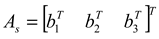 where b is the beam direction vector. Assuming a small value of the lever arm, the velocities in beams (#1, #2 and #3) directions are:
 where
where  is the velocity vector between the platform and tangent frames expressed in the platform frame. From (7), the velocity in the third beam direction is

is the velocity vector between the platform and tangent frames expressed in the platform frame. From (7), the velocity in the third beam direction is
Since  cannot be calculated by the DVL at time k, the estimated velocity
  at time k + 1
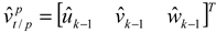 is substituted into (8) to calculate the third beam velocity
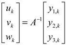
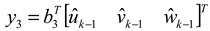 where u is the surge velocity component, v is the sway velocity component and w is the heave velocity component. Plugging the calculated beam #3 velocity (10) together with the measured beam velocities #1 and #2 into (7) yields the DVL platform velocity measurement
cannot be calculated by the DVL at time k, the estimated velocity at time k + 1
Notice that the platform velocity vector, as calculated in (11), is influenced by the DVL measurement noise (in beams #1 and #2) and the process noise (in beam #3); thus, a correlation between the two exists. Therefore, the process and measurement noise cross-covariance matrix should be taken into account in the EKF algorithm. The ELC with the VB approach as described in this section is illustrated in Figure 1.
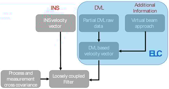
Figure 1.
The extended loosely coupled approach with virtual beam implementation and with the process-measurement noise cross-covariance matrix.
4. Analysis and Results
The EKF with correlated measurements (5) is used for the analysis. All relevant filter parameters can be found in [8]. The simulated AUV trajectory is a straight-line trajectory with constant speed and depth. This trajectory was chosen since in steady-state conditions most AUVs will follow a straight-line trajectory. The simulated AUV speed was 2 m/s for a 100 s trajectory. The inertial sensors were measured at 150 Hz and modeled with a constant bias and zero-mean Gaussian white noise. The DVL assistance was received at a rate of 1 Hz. Each DVL beam measurement was modeled with constant bias and zero-mean Gaussian white noise.
The root mean square (RMS) error is used to evaluate the performance of the proposed approach. Monte-Carlo runs with the 6DOF AUV simulation were conducted and the RMS was calculated for the velocity vector. The IMU residual states and attitude misalignment states are not presented here since no major improvement was obtained comparted to the original ELC approach.
The velocity RMS error with (M = 1) and without (M = 0) the cross-covariance matrix of the correlated process and measurement noises, is presented in Figure 2.
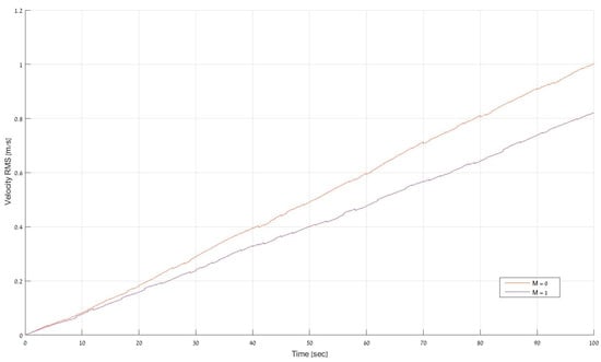
Figure 2.
The velocity RMS error with (M = 1) and without (M = 0) the cross-covariance matrix of the correlated process and measurement noises.
The results when taking into account the cross-covariance matrix are better than without considering it. The rate of improvement increases as the length of the trajectory increases. For example, at the end of the trajectory an improvement of about 18% was achieved. Also, the standalone INS obtained a velocity RMS error of 1.29 m/s at the end of the trajectory which means that that using the original ELC approach an improvement of 22% was obtained while using the ELC approach with the cross-covariance matrix an improvement of 36% was obtained.
5. Conclusions
In this paper, the cross-covariance matrix, representing the correlation between the process and measurement noises, was used in INS/DVL fusion with the ELC approach. Simulation results using a 6DOF simulation show that when considering the correlation covariance matrix, the results improve compared to the original ELC approach. In particular, at the end of the trajectory, an improvement of about 18% was achieved.
Future research will include evaluation of other trajectories and sea experiments to validate the proposed approach.
References
- Paull, L.; Saeedi, S.; Seto, M.; Li, H. AUV navigation and localization: A review. IEEE J. Ocean. Eng. 2014, 39, 131–149. [Google Scholar] [CrossRef]
- Panish, R.; Taylor, M. Achieving high navigation accuracy using inertial navigation systems in autonomous underwater vehicles. In Proceedings of the 2011 IEEE OCEANS, Santander, Spain, 6–9 June 2011. [Google Scholar]
- Klein, I.; Diamant, R. Observability analysis of DVL/PS aided ins for a maneuvering AUV. Sensors 2015, 15, 26818–26837. [Google Scholar] [CrossRef] [PubMed]
- Troni, G.; Whitecomb, L.L. Experimental evaluation of a MEMS inertial measurements unit for Doppler navigation of underwater vehicles. In Proceedings of the Oceans 2012, Hampton Roads, VA, USA, 14–19 October 2012. [Google Scholar]
- Groves, P.D. Principles of GNSS, Inertial, and Multisensor Integrated Navigation Systems; Artech House: Boston, MA, USA, 2008. [Google Scholar]
- Miller, P.A.; Farrell, J.A.; Zhao, Y.; Djapic, V. Autonomous underwater vehicle navigation. IEEE J. Ocean. Eng. 2010, 35, 663–678. [Google Scholar] [CrossRef]
- SBG Systems. Available online: https://www.sbg-systems.com/products/ekinox-ins-high-performance-mems-inertial-system (accessed on 1 October 2018).
- Tal, A.; Klein, I.; Katz, R. Inertial navigation system/Doppler velocity log (INS/DVL) fusion with partial DVL measurements. Sensors 2017, 17, 415. [Google Scholar] [CrossRef] [PubMed]
- Farrell, J.A. Aided Navigation GPS with High Rate Sensors; McGraw-Hill: New York, NY, USA, 2008. [Google Scholar]
- Simon, D. Optimal State Estimation: Kalman, H Infinity, and Nonlinear Approaches; John Wiley & Sons: Hoboken, NJ, USA, 2006. [Google Scholar]
Publisher’s Note: MDPI stays neutral with regard to jurisdictional claims in published maps and institutional affiliations. |
© 2018 by the authors. Licensee MDPI, Basel, Switzerland. This article is an open access article distributed under the terms and conditions of the Creative Commons Attribution (CC BY) license (https://creativecommons.org/licenses/by/4.0/).