Proceeding Paper

Computer Vision Aided Structural Identification: Feature Tracking Using Particle Tracking Velocimetry versus Optical Flow †

1
Institute of Structural Engineering, Department of Civil, Environmental and Geomatic Engineering, ETH Zurich, 8093 Zurich, Switzerland
2
Institute of Environmental Engineering, Department of Civil, Environmental and Geomatic Engineering ETH Zurich, 8093 Zurich, Switzerland
*
Author to whom correspondence should be addressed.
Presented at the 5th International Electronic Conference on Sensors and Applications, 15–30 November 2018; Available online: https://ecsa-5.sciforum.net.
Proceedings 2019, 4(1), 33; https://doi.org/10.3390/ecsa-5-05750
Published: 14 November 2018
(This article belongs to the Proceedings of 5th International Electronic Conference on Sensors and Applications)

Abstract

:
Recent advances in computer vision techniques allow to obtain information on the dynamic behaviour of structures using commercial grade video recording devices. The advantage of such schemes lies in the non-invasive nature of video recording and the ability to extract information at a high spatial density utilizing structural features. This creates an advantage over conventional contact sensors since constraints such as cabling and maximum channel availability are alleviated. In this study, two such schemes are explored, namely Particle Tracking Velocimetry (PTV) and the optical flow algorithm. Both are validated against conventional sensors for a lab-scale shear frame and compared. In cases of imperceptible motion, the recently proposed Phase-based Motion Magnification (PBMM) technique is employed to obtain modal information within frequency bands of interest and further used for modal analysis. The optical flow scheme combined with (PBMM) is further tested on a large-scale post-tensioned concrete beam and validated against conventional measurements, as a transition from lab- to outdoor field applications.

1. Introduction

Advancements in image processing tools and wider availability of high resolution and high frame-rate cameras is opening up new possibilities in measurement techniques for structural identification and structural health monitoring (SHM) frameworks. Many advantages arise via use of such tools over conventional cabled and wireless contact-based sensing technologies, such as higher spatial density of measurement locations, reduction of installation and maintenance costs as well as shorter interruption of operation [1]. This being said, some limitations of computer-vision based techniques still need to be addressed, mainly pertaining to using natural features of the structure, extracting useful information from tiny displacements as well as robustness against changing natural lighting conditions.
Numerous studies exist in the literature involving measurement campaigns both within a laboratory environment, as well as for outdoor deployments. Due to low amplitude displacements experienced by structures in their operational state, many studies exploit a recently suggested enhancement technique, namely the phase-based motion magnification (PBMM) scheme [2], as a pre-processing step of structural identification. PBMM allows to magnify motion within videos in a specified temporal frequency bandwidth. If the selected frequency band lies within a natural frequency of the structure, the resultant magnified motion reveals an approximation of its respective mode shape. Within the SHM domain, this technique was initially used as a qualitative tool for mode-shape visualization [3] but it was later together with its variants adopted for quantitative structural identification problems [4,5,6,7,8].
Albeit limited in number, some outdoor applications exist [9,10,11,12] employing computer vision techniques for dynamic displacement measurements, with and without the use of PBMM. In this work, two feature tracking algorithms, namely particle tracking velocimetry (PTV) and optical flow, were validated and compared against each other and against conventional sensing technologies in order to assess the feasibility of their use in outdoor deployments. A scaled shear frame with uniform background and artificially introduced markers was employed for this comparison. Subsequently, a post-tensioned reinforced concrete beam without any artificially introduced markers or constant fore- and background was utilized to present preliminary research results towards outdoor applications.

2. Methods

2.1. Feature Tracking Methods

2.1.1. Particle Tracking Velocimetry (PTV)

Particle tracking velocimetry is an optical measurement technique originally developed to track Lagrangian trajectories of individual features (tracer particles) in fluid flow. It has been employed in many engineering problems, ranging from tracking bird migration [13] to investigating blood flow [14]. Its use for dynamic displacement measurements was recently explored by the authors [3,4].
Acquired videos are first passed through a high-pass filter in order to reduce pixel noise. Particles are identified based on their grey value intensity and centroid estimation is realized through the arithmetic mean of pixel coordinates weighted by their grey value intensities. The spatial coordinates for each particle are derived via the collinearity condition, which states that image point, camera projective centre and object point lie on a straight line [15]. Subsequent linking of particles in successive images and construction of displacement trajectories is achieved by position prediction based on a constant velocity assumption. This assumption holds true for sufficiently fast sampling.

2.1.2. Lucas-Kanade Method for Optical Flow

Optical flow [16,17] is the pattern of apparent motion between two consecutive images caused by movement of an object or the camera. It assumes consistent brightness between two consecutive frames. To compute the optical flow the Lucas-Kanade method (KLT tracker) [18] assumes that neighbouring pixels comprise similar motion and operate over a patch (N × N window) around the point to estimate the flow as described in Equation (1).
u v = H 1 i I x i I t i i I y i I t i   a n d   H = i I x i 2 i I x i I y i i I x i I y i i I y i 2 ,
where u and v denote horizontal and vertical displacement increments between two consecutive frames and I x , I y , I t correspond to partial derivatives of the frame intensity function over spatial coordinates x, y and time t, with i = 1 , 2 , , N .
Appropriate features for tracking necessitate a well-conditioned (invertible) H, implying that its eigenvalues λ 1 and λ 2 should not be too small, while the ratio λ 1 / λ 2 should not be too large. Edge features typically comprise large λ 1 and small λ 2 and low-texture regions lead to small λ 1 and λ 2 values. In contrast, high textured features like corners and blobs have a well-conditioned H matrix and thus are easier to track. These features are highly distinct and usually selected for tracking, by means of relevant feature detection algorithms [17]. This work employs the pyramidal implementation of the Lucas-Kanade method [19], which can also handle large motions.

2.1.3. Phase-Based Motion Magnification (PBMM)

The recently proposed phase-based motion magnification scheme has gained considerable attention within the SHM domain, since it allows to amplify motion in videos where motion is otherwise imperceptible (subpixel range) and not straightforward to track for dynamic displacements. The method relies on exploiting local phase variations within a video over time in different spatial orientations and scales. This is achieved via use of complex steerable pyramids, which is a transform that can decompose an image according to its spatial scale, orientation and position. Local phase variations are separated, temporally filtered at each independent position, orientation and scale via the pyramid. Resultant phases are then amplified and reconstructed to form the motion magnified video [20]. A MATLAB based script was made available by Wadhwa et al. [2] and interested readers are directed to the cited work.

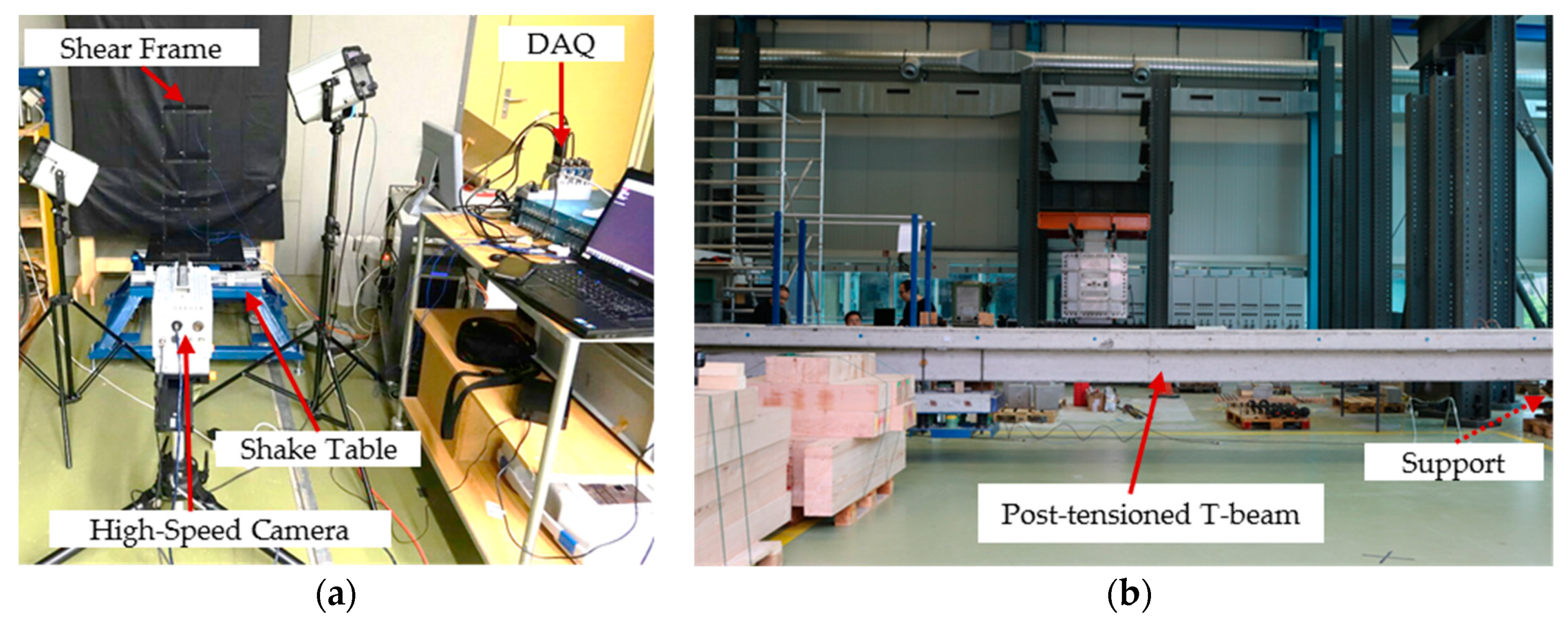
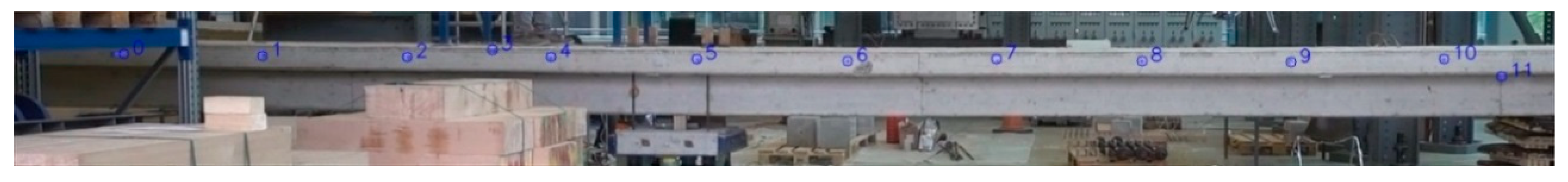
2.2. Experimental Setup Description

In order to validate and compare the previously described methodologies, two distinct experimental campaigns were undertaken. First, a scaled three story shear frame was tested in front of a uniform background and subsequently a 17.4 m post-tensioned reinforced concrete T-beam was tested using the natural background of the laboratory. Both specimens are presented in Figure 1.
The shear frame was fixed onto a uniaxial small-scale shake table and comprises a 200 mm idealized story height and a floor area of 200 × 200 mm. Steel columns with a cross section of 10 × 3 mm were connected to aluminium plates with 15 mm thickness. The entire frame was painted black and 2 mm diameter white markers were introduced on the structure. A black background was positioned behind the frame and illumination was realized via two LED spotlights. A high speed camera equipped with a 28 mm f/2.8D lens was employed at 1024 × 1024 pixel resolution and 500 fps for video recording from a 2 m distance to the frame. In addition, four piezoelectric uniaxial accelerometers were deployed at the centroid of each story, along with a linear variable displacement transducer (LVDT) at the shake table base and a laser transducer at the top floor. The frame was excited via the scaled 1994 Northridge earthquake as well as a hammer impact.
The post-tensioned reinforced concrete T-beam was equipped with 8 piezoelectric uniaxial accelerometers and structural response was recorded via an off-the-shelf camera (SonyRX100V) with 50 fps and 1920 × 1080 pixel resolution, positioned approximately 10 m from the beam. It comprises a 17.4 m span length, 0.48 m beam depth, 0.9 m flange width, 0.18 flange depth and a web width of m, with a total mass of 9740 kg. The beam was kept in natural lighting conditions without any special considerations regarding background and surface preparation. Due to space constraints within the laboratory, the entire beam could not be recorded with the camera. Moreover, it can be clearly observed in Figure 1b that some obstacles exist in front of the beam. An impact excitation was introduced onto the structure by jumping.

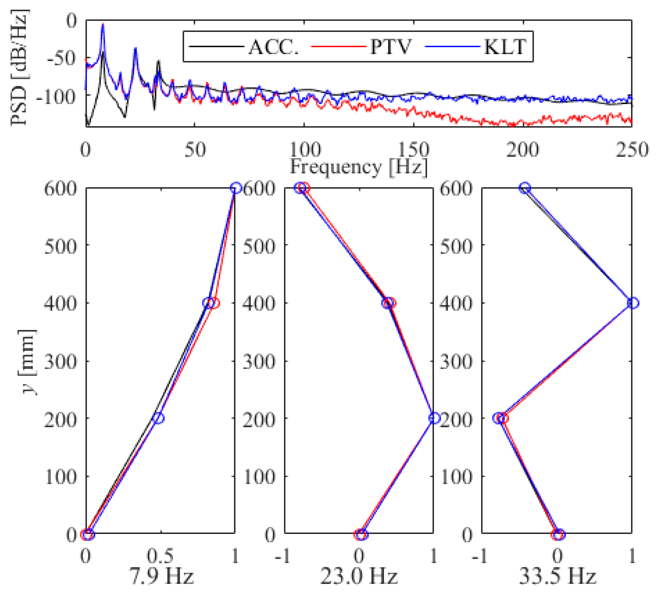
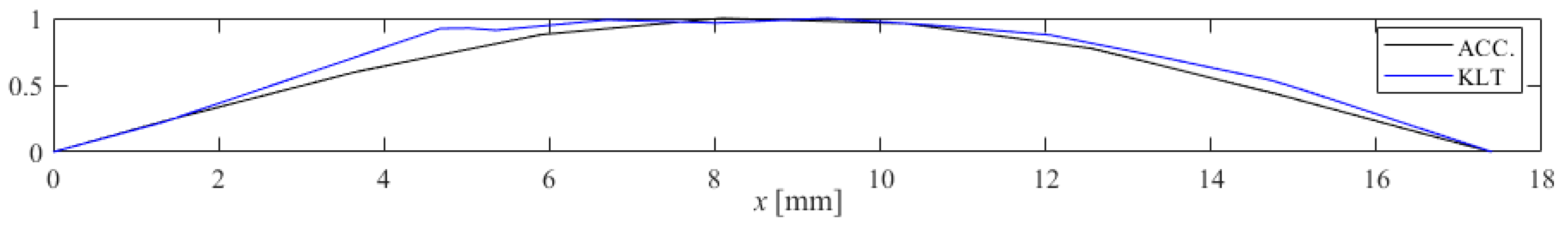
3. Results and Discussion

The results reported herein are presented and discussed in two separate tracks, the first one pertaining to the validation of both feature tracking schemes against the scaled shear frame and a second one assessing the ability of KLT coupled with PBMM to extract mode shapes. Displacement response obtained via PTV and KLT at the top story of the frame correlate very well to those inferred via the laser transducer (reference measurement), presented for the Northridge base excitation (Figure 2a) and hammer impact excitation (Figure 2b). Linear correlation was calculated as 0.963 between the laser and PTV and 0.947 between the laser and KLT.
The power spectral density (PSD) estimates of unfiltered displacement signals from both feature tracking techniques (also provided in Figure 2b) are compared against the PSD obtained from accelerometer measurements in Figure 3. Furthermore, displacement and accelerations extracted from each story are employed within a modal analysis framework using the stochastic subspace identification (SSI) technique [21]. Figure 3 reports on the resulting first three identified modes of the structure. It is evident that both techniques result in mode shapes that are well correlated with the ones obtained via accelerometers. Moreover, natural frequencies resulting from presented stable physical modes accurately match with reference (accelerometer) results, displaying a maximum error deviation of 0.27%.
As previously mentioned, a second experimental campaign was undertaken on a post-tensioned concrete beam. Motion of this beam following impact excitation was registered to be at sub-pixel level due to high stiffness of the structure. To this end, the aforementioned PBMM technique was employed as a pre-processing step in order to amplify motion within a defined frequency band. The frequency band (1.7–1.9 Hz) was selected based on the first identified peak in accelerometer measurements corresponding to the first bending mode shape and a magnification factor of α = 5 was selected. As no external markers were applied on the structure, formwork plugs that are still attached to the beam were used as features to be tracked by KLT, as demonstrated in Figure 4. Theoretically, these features can also be utilized for PTV yet a preliminary background subtraction process would be needed, which was not undertaken in this work.
Analogue to the shear frame, amplified motion extracted via KLT was fed into the SSI algorithm and the resultant normalized mode shape was compared against the one obtained from measured accelerations. As seen in Figure 5, a relatively good correspondence was achieved, despite the extremely sub-optimal front- and background and a slightly skewed camera angle.

4. Conclusions and Outlook

In this work, two feature-based tracking techniques have been employed on video recordings and compared against conventional sensor technologies. Both methods perform well in capturing the structural response of a scaled shear frame comprising a regular background and high contrast features. In order to tackle problems pertaining to future large-scale outdoor deployments, a full-scale beam was tested without artificially introduced features and within an irregular fore- and background environment. Impact response was magnified via the PBMM tool around the first natural frequency and structural features were tracked via KLT, revealing that mode shapes correlate well to accelerometer data. PTV was not utilized for the beam due to the need of background subtraction, yet future outdoor use is still foreseen in night applications or if sufficient contrast is ensured. Envisioned future work pertains to testing the feasibility of applying the presented techniques within natural lighting environments and utilizing structural various features instead of artificial markers.

Author Contributions

Conceptualization, Y.E.H., Z.L. and E.C.; methodology, Y.E.H., U.G. and Z.L.; investigation, Y.E.H. and U.G.; writing—original draft preparation, Y.E.H. and Z.L.; writing—review and editing, M.H. and E.C.; supervision, M.H. and E.C.

Funding

Prof. Chatzi would like to acknowledge the ERC Starting Grant (ERC-2015-StG #679843) on the topic of “Smart Monitoring, Inspection and Life-Cycle Assessment of Wind Turbines”, as well as the supplemental equipment grant SNSF R’Equip # 2-77242-17 and the Proof of Concept Grant ERC-2018-PoC WINDMIL RT-DT, in the context of which such non-contact technologies are explored.

Acknowledgments

Technical staff of the Structural Engineering Research Laboratory at ETH Zürich and Nan Zhu, Yaowen Ou and Lucas Teixeira are kindly acknowledged for their support in experiments.

Conflicts of Interest

The authors declare no conflict of interest.

References

  1. Xu, Y.; Brownjohn, J.M.W. Review of machine-vision based methodologies for displacement measurement in civil structures. J. Civ. Struct. Heal. Monit. 2017, 8, 1–20. [Google Scholar] [CrossRef]
  2. Wadhwa, N.; Rubinstein, M.; Durand, F.; Freeman, W.T. Phase-based video motion processing. ACM Trans. Graph. 2013, 32, 80. [Google Scholar] [CrossRef]
  3. Chen, J.G.; Wadhwa, N.; Cha, Y.-J.; Durand, F.; Freeman, W.T.; Buyukozturk, O. Modal identification of simple structures with high-speed video using motion magnification. J. Sound Vib. 2015, 345, 58–71. [Google Scholar] [CrossRef]
  4. Cha, Y.-J.; Chen, J.G.; Büyüköztürk, O. Output-only computer vision based damage detection using phase-based optical flow and unscented Kalman filters. Eng. Struct. 2017, 132, 300–313. [Google Scholar] [CrossRef]
  5. Yang, Y.; Dorn, C.; Mancini, T.; Talken, Z.; Kenyon, G.; Farrar, C.; Mascareñas, D. Blind identification of full-field vibration modes from video measurements with phase-based video motion magnification. Mech. Syst. Signal Process. 2017, 85, 567–590. [Google Scholar] [CrossRef]
  6. Sarrafi, A.; Mao, Z.; Niezrecki, C.; Poozesh, P. Vibration-based damage detection in wind turbine blades using Phase-based Motion Estimation and motion magnification. J. Sound Vib. 2018, 421, 300–318. [Google Scholar] [CrossRef]
  7. Zimmermann, M.; Gülan, U.; Harmanci, Y.E.; Chatzi, E.N.; Holzner, M. Structural Health Monitoring through Video Recording. In Proceedings of the 8th European Workshop on Structural Health Monitoring (EWSHM 2016), Bilbao, Spain, 5–8 July 2016. [Google Scholar]
  8. Harmanci, Y.E.; Gülan, U.; Zimmermann, M.; Holzner, M.; Chatzi, E. High spatial density vibrational measurements via 3D-particle tracking velocimetry. In Proceedings of the 4th Conference on Smart Monitoring, Assessment and Rehabilitation of Civil Structures (SMAR 2017), Zurich, Switzerland, 13–15 September 2017. [Google Scholar]
  9. Xu, Y.; Brownjohn, J. Non-contact vibration measurement of cables in a cable-stayed bridge by consumer-grade camera. In Proceedings of the 4th Conference on Smart Monitoring, Assessment and Rehabilitation of Civil Structures (SMAR 2017), Zurich, Switzerland, 13–15 September 2017. [Google Scholar]
  10. Ribeiro, D.; Calçada, R.; Ferreira, J.; Martins, T. Non-contact measurement of the dynamic displacement of railway bridges using an advanced video-based system. Eng. Struct. 2014, 75, 164–180. [Google Scholar] [CrossRef]
  11. Khuc, T.; Catbas, F.N. Computer vision-based displacement and vibration monitoring without using physical target on structures. Struct. Infrastruct. Eng. 2017, 13, 505–516. [Google Scholar] [CrossRef]
  12. Chen, O.B.J.G.; Davis, A.; Wadhwa, N.; Durand, F.; Freeman, W.T. Video Camera–Based Vibration Measurement for Civil Infrastructure Applications. J. Infrastruct. Syst. 2016, 23, B4016013. [Google Scholar] [CrossRef]
  13. Cavagna, A.; Giardina, I. Bird Flocks as Condensed Matter. Annu. Rev. Condens. Matter Phys. 2014, 5, 183–207. [Google Scholar] [CrossRef]
  14. Gülan, U.; Lüthi, B.; Holzner, M.; Liberzon, A.; Tsinober, A.; Kinzelbach, W. Experimental study of aortic flow in the ascending aorta via Particle Tracking Velocimetry. Exp. Fluids 2012, 53, 1469–1485. [Google Scholar] [CrossRef]
  15. Maas, H. Contributions of digital photogrammetry to 3D PTV. In Proceedings of the Three-Dimensional Velocity and Vorticity Measuring and Image Analysis Techniques, Zürich, Switzerland, 3–6 September 1996; pp. 191–207. [Google Scholar]
  16. Gibson, J.J. The Perception of the Visual World; Houghton Mifflin: Cambridge, MA, USA, 1950. [Google Scholar]
  17. Radke, R.J. Computer Vision for Visual Effects; Cambridge University Press: Cambridge, UK, 2013. [Google Scholar]
  18. Lucas, B.D.; Kanade, T. An iterative image registration technique with an application to stereo vision. In IJCAI’81 Proceedings of the 7th international joint conference on Artificial intelligence, Vancouver, BC, Canada, 24–28 August 1981. [Google Scholar]
  19. Bouguet, J.-Y. Pyramidal implementation of the affine lucas kanade feature tracker description of the algorithm. Intel Corp. 2001, 5, 4. [Google Scholar]
  20. Rubinstein, M. Analysis and Visualization of Temporal Variations in Video; Massachusetts Institute of Technology: Cambridge, MA, USA, 2014. [Google Scholar]
  21. Van Overschee, P.; De Moor, B.L. Subspace Identification for Linear Systems: Theory—Implementation—Applications; Springer Science & Business Media: Berlin/Heidelberg, Germany, 2012. [Google Scholar]
Figure 1. Overview of the (a) shear frame and (b) post-tensioned reinforced concrete T-beam test setup and their key components. The image in subfigure (b) is taken by the same camera that is utilized for measurements.
Proceedings 04 00033 g001
Figure 2. Horizontal displacements measured during (a) Northridge base excitation and (b) Hammer impact via laser transducer, PTV and KLT.
Proceedings 04 00033 g002
Figure 3. Unfiltered power spectral densities and normalized mode shapes extracted from accelerometers (ACC.), PTV and KLT.
Proceedings 04 00033 g003
Figure 4. Tracked features of the post-tensioned reinforced concrete beam via KLT.
Proceedings 04 00033 g004
Figure 5. Normalized bending mode shape extracted from accelerometers (ACC.) and KLT following motion magnification.
Proceedings 04 00033 g005

