Abstract
A simple transient effect method for the determination of the spin-lattice relaxation time using continuous wave NMR (TEDSpiL) with a marginal oscillator was recently reported (doi:10.1002/mrc.4594). Such a system measures a parameter called Tx that is related to T1 and allows T1 to be determined with the aid of calibration samples. For such a system, the process of making the Tx measurement does not require variable parameters and so is ideal for implementing in microcontroller code. In this article, we demonstrate that TEDSpiL may be automated using two microcontrollers from the Teensy family to make a low power and portable system.
1. Introduction
Nuclear magnetic resonance (NMR) has many applications, from the chemical fingerprints of NMR spectroscopy [1] to the whole body magnetic resonance imaging (MRI) scanners found in many hospitals [2]. Two of the parameters that can be used in the production of MRI images are the spin-lattice (T1) and spin-spin (T2) relaxation times, and measurements of these have been used in a wide variety of sensor applications that may use permanent magnets and less expensive electronics [3,4,5]. Most applications use pulsed NMR for these measurements; however, continuous wave (CW), which was the predecessor to pulsed, is conceptually simpler and has simpler electronics but is often more difficult to implement and so fell out of favor. Recent advances in permanent magnet technology and speed of low-cost electronics have sparked some interest in the topic and the electronics have been recently reviewed [6]. A simplified view of NMR considers the intrinsic nuclear magnetic moments of certain nuclei to be like microscopic bar magnets that tend to orientate in a generally aligned manner with or opposed to the presence of a strong magnetic field (𝐵0). Radio frequency (rf) radiation can be absorbed at a frequency that satisfies the Larmor condition 𝜔 = 𝛾𝐵0 (where 𝜔 is the angular frequency and 𝛾 is the gyromagnetic ratio which is a constant for a given nucleus) corresponding to the energy difference between the two states. In CW-NMR, either the frequency of the rf can be fixed and the magnetic field swept through the resonance condition, or the magnetic field is held constant and the frequency of the rf changes. Where the field is swept, an alternative strategy is to use a marginal oscillator where the oscillation amplitude dips as it passes through resonance [7,8]. Look and Locker [9] demonstrated that there is a transient effect when the sweep of the magnetic field is initiated and that this may be used to determine the value of T1. More recently, a simple variation using a marginal oscillator and calibration samples was presented, which is referred to as the transient effect determination of the spin-lattice relaxation time using continuous wave NMR, or TEDSpiL [10]. In this work we demonstrate that TEDSpiL may be automated using two microcontrollers from the Teensy family.
2. Materials and Methods
A schematic diagram of the continuous wave system is shown in Figure 1. The sample is placed in a coil which forms part of a marginal oscillator tank circuit. For convenience, we use a commercial marginal oscillator operating from around 14 MHz to 21 MHz [11]; however, there have been many different marginal oscillator circuits published, which were reviewed recently [6]. The coil used, also produced by LD Didactic as part of their NMR probe bar (514–606), is placed in the fixed magnetic field with sweep coils that allow the field to be swept about the resonance value. The fixed field can be produced by using Neodymium Iron Boron (NdFeB) magnets, as shown in Figure 1, or by electromagnet coils; however, the latter do draw significant current and cause elevated sample temperatures. A digital to analogue converter on a Teensy 3.5 [12] microcontroller is used to generate 100 cycles of a voltage ramp which are amplified using a power amplifier built from a 2N3055H power transistor and LM 358N buffer amplifier [10] and providing a gain of five, before driving the sweep coils (part of the 514–606). The oscillator frequency is adjusted such that the resonance occurs at the center of the ramp. The ramp is started using a push button attached to a digital input (pin 12) on the Teensy 3.5 microcontroller and a digital output (pin 11) is used to trigger a Teensy 3.6 [13] to make measurements of the marginal oscillator output after it has been amplified by a simple inverting op-amp (MCP6002) with a 1 kΩ input resistor and a 10 kΩ feedback resistor, giving a gain of −10. A liquid crystal display (LCD) is attached to pin 10 of the Teensy 3.5 to display the calculated value of Tx. The code for the Teensy 3.5 is shown in Supplementary S1.
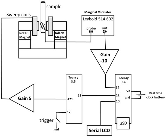
Figure 1.
Schematic diagram of the experimental arrangement. Only the power (4.5V to ‘Vin’ pins) and ground (power ground to pin ‘GND’ and analogue input ground to ‘Analog GND’) connections have been left off the Teensy circuits, and the gain −10 amplifier is an inverting op-amp.
The Teensy 3.6 is a 32-bit 180 MHz ARM Cortex-M4 processor with floating point unit, 256 Kbytes of RAM, and 1024 Kbytes of flash memory, including an on-board microSD card holder. It costs less than US$30. It contains two analogue to digital converters (ADC) with a usable resolution of 13 bits. Much of the material for the Teensy was developed open source by Paul Stoffregen and his team at pjrc.com; however, there is an implementation library for the ADC that was created by Pedro Villanueva [14] which allows the full power of the ADC to be utilized
For maximum speed, data are saved into an array in memory, and the maximum array size for 16-bit sample data is around 64,000 data points. This is not sufficient to capture the whole of the data for 60 sweeps at 40 Hz, and a lower sample rate may not clearly identify the peak value. To allow for this, the Teensy 3.5 provides a trigger pulse to the Teensy 3.6 a quarter of the way up the ramp sweep so that only the 1000 points around the peak are captured to an array in memory. It is then a straightforward loop to find the maximum value within those data to give the peak value which is stored in a separate array of peak values.
The Teensy 3.6 code then carries out a simple least squares fit on the natural log of the peak values, and the gradient gives a value for Tx, which is displayed on the serial LCD display. The time from pressing the trigger to the display of Tx is less than five seconds, and the system then waits for a further ten seconds before the trigger can be pressed again to allow the sample to equilibrate away from the resonant value of magnetic field. All the data from the arrays and the peak values are stored on the onboard microSD card with the real time clock being used to generate a file name which is the last 8 digits of the UNIX time stamp of when the measurement was made. It should be noted that the Teensy 3.6, unlike the 3.5, is not 5 V tolerant, so the amplifier is supplied with only 3 V from two 1.5 V batteries, and both the Teensy 3.5 and 3.6 are supplied with 4.5 V from three 1.5-volt batteries. In our circuit, both amplifier and Teensy share batteries to save weight, and the amplifier supply is ‘tapped’ off.
3. Results
Figure 2 shows the number returned from the Teensy 3.6 ADC from the amplified marginal oscillator signal for a single magnetic field sweep. With a sampling speed of around 160 kSample/second, this demonstrates that the Teensy ADC is capable of accurately capturing the peak amplitude. Note that the positive going “wiggles’” that are common in this type of system [6] are also visible, but as we are only interested in the peak value, no offset is provided to the amplifier to capture the negative going part of the ”wiggles”. By triggering the 3.6 to capture partway through the sweep ramp, it is easily possible to capture up to 60 peaks with the available RAM, but only around 25 peaks are required to get a reasonable linear fit to provide a value for Tx; the first five values are also discarded.
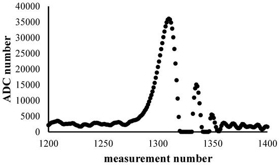
Figure 2.
The number returned from the Teensy 3.6 ADC (analogue to digital converter) from the amplified marginal oscillator signal for a single magnetic field sweep. This demonstrates that the Teensy ADC is capable of accurately capturing the peak amplitude.
Figure 3 shows a typical example for a sample of water of natural log of the peak amplitude from the amplified marginal oscillator signal as a function of time for peaks 5 to 25. Note that the scatter in the data increases as the marginal oscillator peak amplitude tends towards the equilibrium value, so including peaks beyond the 25th does not improve the Tx measurement. In Figure 4, we show a set of Tx values as a function of the concentration of copper sulphate, which is often used as a standard test set of T1 values in pulsed NMR; the change is consistent with data reported for pulsed NMR [15,16].
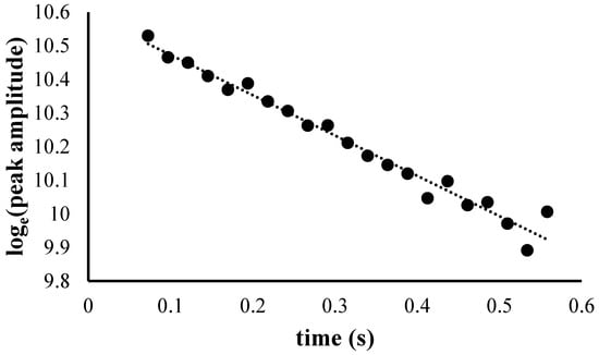
Figure 3.
Typical example for water of the natural log of the peak amplitude from the amplified marginal oscillator signal as a function of time for peaks 5 to 25. The gradient of the linear fit, shown as the dotted line, gives a value for Tx.
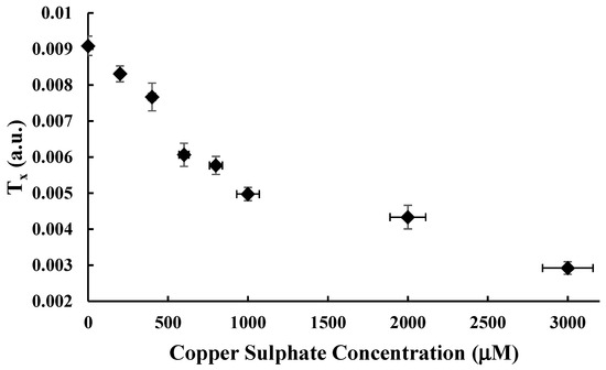
Figure 4.
Tx values as a function of concentration of copper sulphate in water.
4. Discussion
The electronics, commonly referred to as the console, for low field pulsed NMR systems typically cost in excess of $20k as they are designed to be wide band and highly programmable spectrometers. The process of making T1 measurements with such a pulsed system usually uses recovery sequences that will typically take many minutes to give a single T1 value. Whilst the Tx value is not a direct equivalent to T1, there are applications where the use of Tx may provide a cost-effective measurement solution. One such application may be to sample the outlet water from a constructed wetland treatment bed for coal mine drainage water. Such water often contains iron oxide, which is a known T1 contrast agent, and the presence of a significant amount of iron oxide in the water would indicate that a constructed wetland bed is no longer functioning correctly and that remediation work is required. As there are environmental, and possibly financial, consequences for clogged beds discharging untreated water, the measurement system reported in this article could form the basis of an appropriate monitoring system.
Author Contributions
Conceptualization and Methodology, M.I.N. and R.H.M.; Software, M.I.N. and S.T.P.; Investigation, M.I.N. and S.T.P.; Writing—Original Draft Preparation, M.I.N.; Writing—Review & Editing, R.H.M. and S.T.P.
Funding
This research received no external funding.
Conflicts of Interest
The authors declare no conflict of interest.
References
- Weber, U.; Thiele, H. NMR Spectroscopy: Modern Spectral Analysis, 1st ed.; Wiley VCH: Weinheim, Germany, 1998; ISBN-10 3527288287. [Google Scholar]
- Dale, B.M.; Brown, M.A.; Semelka, R.C. MRI: Basic Principles and Applications; Wiley-Blackwell: Hoboken, NJ, USA, 2015; ISBN-10 1119013054. [Google Scholar]
- Blumich, B.; Perlo, J.; Casanova, F. Mobile single-sided NMR. Prog. Nucl. Magn. Reson. Spectrosc. 2008, 52, 197–269. [Google Scholar] [CrossRef]
- Blümich, B. Introduction to compact NMR: A review of methods. Trends Anal. Chem. 2016, 83, 2–11. [Google Scholar] [CrossRef]
- Kirtil, E.; Cikrikci, S.; McCarthy, M.J.; Oztop, M.H. Recent advances in time domain NMR & MRI sensors and their food applications. Curr. Opin. Food Sci. 2017, 17, 9–15. [Google Scholar] [CrossRef]
- Newton, M.I.; Breeds, E.A.; Morris, R.H. Advances in Electronics Prompt a Fresh Look at Continuous Wave (CW) Nuclear Magnetic Resonance (NMR). Electronics 2017, 6, 89. [Google Scholar] [CrossRef]
- Robinson, F.N.H. A high field nuclear magnetic resonance probe using transistors. J. Sci. Instrum. 1965, 42, 653–654. [Google Scholar] [CrossRef]
- Wilson, K.J.; Vallabhan, C.P.G. An improved MOSFET-based Robinson oscillator for NMR detection. Meas. Sci. Technol. 1990, 1, 458–460. [Google Scholar] [CrossRef]
- Look, D.C.; Locker, D.R. Nuclear Spin-Lattice Relaxation Measurements by Tone-Burst Modulation. Phys. Rev. Lett. 1968, 20, 987–989. [Google Scholar] [CrossRef]
- Morris, R.H.; Mostafa, N.; Parslow, S.; Newton, M.I. Transient effect determination of spin–lattice (TEDSpiL) relaxation times using continuous wave NMR. Magn. Reson. Chem. 2017, 55, 853–855. [Google Scholar] [CrossRef] [PubMed]
- LD Didactic GmbH, Hürth, Germany part number 514–602. http://www.ld-didactic.de/ (accessed on 22 January 2019).
- Teensy USB Development Board 3.5. Available online: https://www.pjrc.com/store/teensy35.html (accessed on 19 June 2018).
- Teensy USB Development Board 3.6. Available online: https://www.pjrc.com/store/teensy36.html (accessed on 19 June 2018).
- Teensy 3.x/LC ADC Implementation. Available online: https://github.com/pedvide/ADC (accessed on 19 June 2018).
- Van Geet, A.L.; Hume, D.N. Measurement of Proton Relaxation Times with a High Resolution Nuclear Magnetic Resonance Spectrometer. Progressive Saturation Method. Anal. Chem. 1965, 37, 979–983. [Google Scholar] [CrossRef]
- Thangavel, K.; Saritas, E.U. Aqueous paramagnetic solutions for MRI phantoms at 3 T: A detailed study on Relaxivities. Turk. J. Electr. Eng. Comput. Sci. 2017, 25, 2108–2121. [Google Scholar] [CrossRef]
© 2018 by the authors. Licensee MDPI, Basel, Switzerland. This article is an open access article distributed under the terms and conditions of the Creative Commons Attribution (CC BY) license (https://creativecommons.org/licenses/by/4.0/).