Proceeding Paper

High Sensitivity Optical Sensing Based on Modal Interferences in One-Dimensional Photonic Crystals †

by
Luis Torrijos-Morán
and
Jaime García-Rupérez
*
Nanophotonics Technology Center (NTC), Universitat Politècnica de València, 46022 Valencia, Spain
*
Author to whom correspondence should be addressed.
Presented at the 5th International Electronic Conference on Sensors and Applications, 15–30 November 2018; Available online: https://ecsa-5.sciforum.net.
Proceedings 2019, 4(1), 20; https://doi.org/10.3390/ecsa-5-05714
Published: 6 November 2018
(This article belongs to the Proceedings of 5th International Electronic Conference on Sensors and Applications)

Abstract

:
A one-dimensional photonic crystal supporting two modes is presented as an interferometric integrated optical sensor. The sensing is carried out by obtaining the phase difference between both modes propagated through the same nanometric structure and how it changes when a refractive index (RI) variation over the sensor takes place. Due to the slow-light phenomenon, high sensitivities values are reached near the photonic bandgap edge region. As a result, a high performance, compact, and single-channel optical sensing approach is theoretically calculated and demonstrated with a wide range of applications in the biosensing field.

1. Introduction

During the last decade, new types of optical biosensors have been emerging as a consequence of the advances in different technologies, like biophotonics [1,2]. Within this area, optical integrated sensors based on resonators, plasmonics, or interferometers offer remarkable advantages in terms of sensitivity and compactness for label-free biosensing applications [3,4]. This is the case of Mach–Zehnder Interferometers (MZI), which have been widely used for sensing purposes due to their high sensitivity [5,6]. However, sensors based on this configuration use the phase difference between two waves travelling by different optical paths to perform the sensing. To achieve enough phase shift, long lengths are desired as well as additional photonic structures to separate and recombine the signal, which supposes a disadvantage for its integration in reduced sensing devices with small footprints. On the other hand, modal interferometric configurations have appeared as an alternative to classic interferometers with two arms. This is the case of the bimodal waveguide [7], where the sensing is produced as a result of the phase difference between two modes of light with the same polarization travelling through the same guiding structure. This sensor presents additional advantages with respect to the MZI: higher surface sensitivity for the detection of biological substances and higher compactness since no extra structures are needed. Nevertheless, the requirement of short lengths is not yet accomplished and therefore the need to significantly decrease the size of the whole structure still exists.
In this work, we report a new modal sensing approach using a one-dimensional photonic crystal structure working in the slow-light regime, which allows for overcoming the drawback of bimodal waveguides about the sensor dimensions. Similar structures were firstly described in [8,9] for several photonic functionalities, and used in sensing applications in [10] for the detection of the Bovine Serum Albumin (BSA) protein. Here, we go a step further presenting the possibility of sensing with the phase shift of two different modes supported by this configuration, and thereby, obtaining a short and single-channel interferometric sensor.

2. Methods

2.1. Photonic Crystal Design

A photonic crystal (PhC) can be modeled as a periodic repetition of a certain material permittivity in the space, creating a lattice of refractive indices in one, two, or three dimensions [11]. Similarly to condensed matter theory with electrons, the periodic dielectric distribution of a photonic crystal affects photons creating forbidden bands for which the light cannot propagate throw the structure: the so-called photonic bandgap (PBG). Near the PBG region, the group velocity of the electromagnetic wave is reduced as a consequence of the high dispersion relation in that area, giving rise to the so-called slow-light phenomenon [12]. This effect enhances the interaction of light with the medium on the photonic structure, which is quite interesting for biosensing purposes [13]. The design of our structure is shown in Figure 1, as a one-dimensional periodic repetition of a transversal corrugation element in a single-mode waveguide made of silicon (n = 3.45) over a silica substrate (n = 1.45). The dimension parameters have been chosen to willfully design a PBG in the infrared region, around 1500 nm wavelength in the telecom optical band.
Several simulations have been carried out to characterize the sensor performance. To do this, the open-source software MIT Photonics Bands (MPB) based on the solutions of the definite-frequency eigenstates of Maxwell’s equations in periodic structures has been used in order to obtain the band diagrams of our designs [14]. For an arbitrary range of wavevectors and using three dimensional and fully-vectorial methods, we can obtain the dispersion relation of the Bloch modes propagating through a specific periodic structure. In other words, we can calculate the phase difference existing between two modes in a range of wavelengths and for a given cladding refractive index unit (RIU). Figure 1b depicts the dispersion relation near the PBG for two different cladding refractive indices and for both Bloch modes. As it can be seen, the band is folded as a result of the anti-crossing effect between two modes, creating a stop band for wavelengths below that point and obtaining low slopes, and therefore low group velocities (slow-light) around the region between 1560 nm and 1590 nm.

2.2. Principle of Operation

The input section of the structure is designed in a way that only supports the fundamental mode of the transverse-electric (TE) polarization, single mode condition. Due to the symmetry junction between the single-mode waveguide at the input and the 1D PhC, only the even modes of the TE polarization will be excited in the periodic structure and will contribute to the excitation of the fundamental TE mode at the output waveguide. The phase shift increment between the two modes for different refractive index (RI) over the PhC may be expressed as
φ = L δ k 1 δ k 2 ,
where L is the bimodal length in the z axis and δ k n the wavevector difference in the z axis between both modes for medium 1 and 2, respectively. Accordingly, the sensitivity value of the interferometer as a function of the phase shift [15] is generally described by Δφ/RIU in units of 2π rad/RIU. However, a spectral analysis is also possible by tracking the resonances that are produced as a result of a destructive interference between the modes. This effect takes place when the phase shift is an odd integer number of times π. Consequently, for a given length, there will be some wavelengths for which this condition is fulfilled, producing resonances in the spectrum that will be shifted when the RI changes. We can obtain the power relation as a function of wavelength by simply propagating two waves using their propagation constant or wavevector in the z direction:
P o u t / P i n = 0.5 e j k 1 L + e j k 2 L .
The minimum values of this equation are obtained for those wavelengths where the phase shift generates destructive interferences. According to [16], we can define the spectral sensitivity by dividing the total wavelength shift by the refractive index variation: S ( λ ) = λ / R I U in units of nm/RIU. Two different sensitivity expressions are therefore defined, depending on the phase or wavelength shift, both for a given refractive index variation that determines the sensor sensitivity.

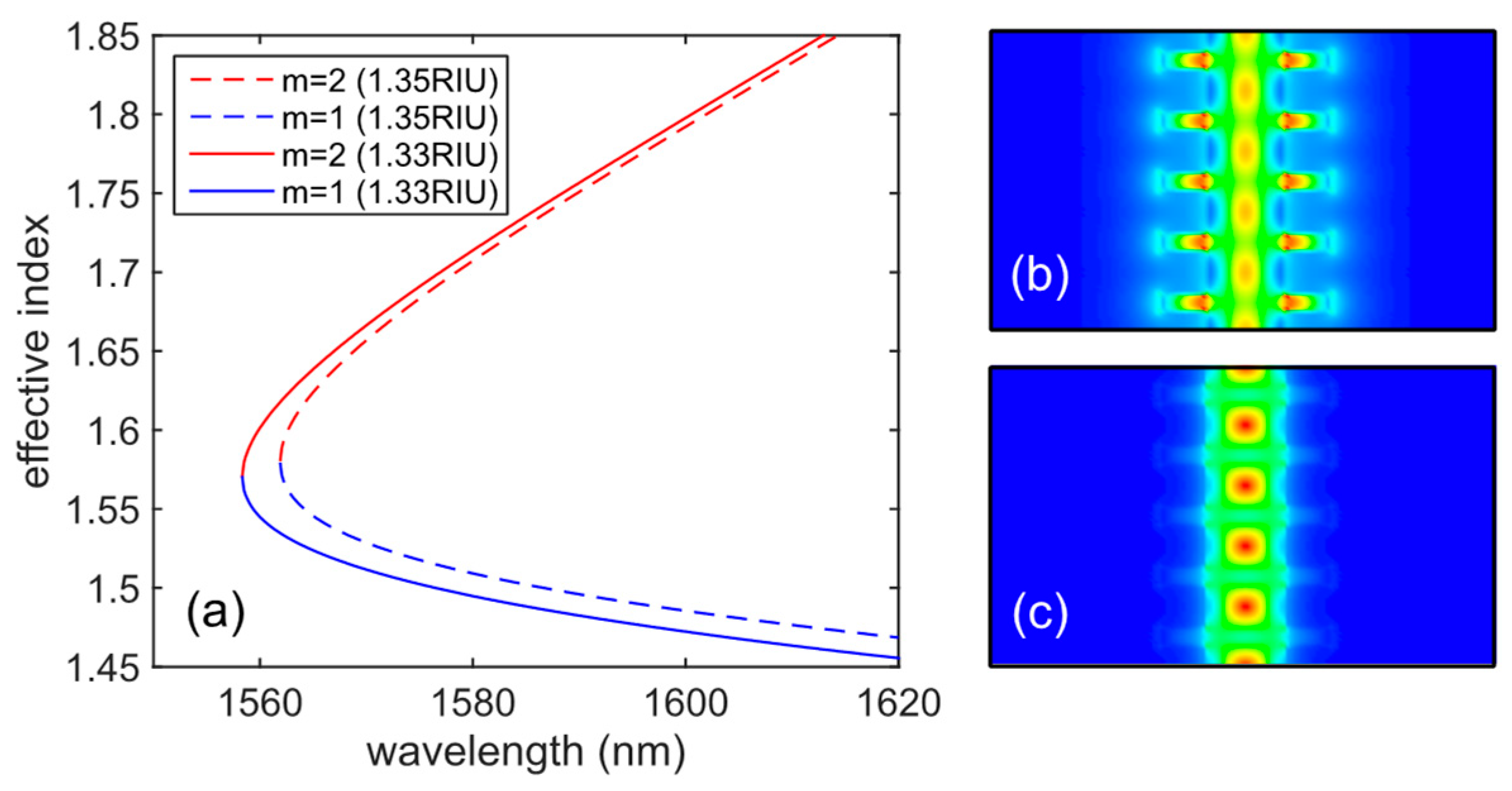
3. Results and Discussion

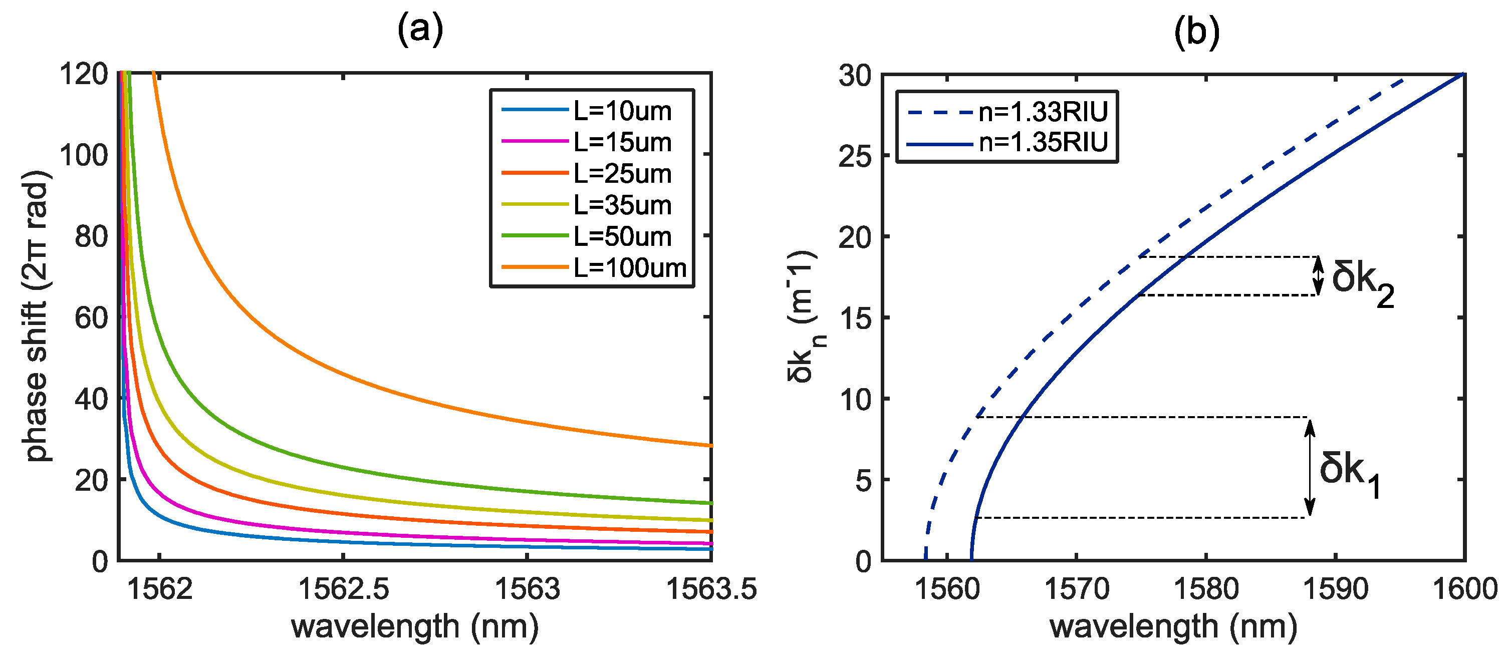
3.1. Interferometric Performance of the Sensor

Using the band diagrams that were obtained in MPB, we can calculate the effective refractive index of each mode under a cladding RI variation, and see how it behaves for different wavelengths. Figure 2a shows this evolution at the bimodal region. In addition, the energy density of each mode is also depicted in Figure 2b,c, in order to estimate the electromagnetic field distribution in our periodic structure. This will help us to determine which mode is more sensitive and how the sensor works for RI changes.
As may be noted, mode 1 has a lower effective index than mode 2, which means that the field is less confined in the structure and, for this reason, a higher interaction with the cladding will be produced for this mode. Accordingly, mode 2 varies less than mode 1 when an increment of 0.02 RIU is carried out, acting as a reference arm in a classic interferometric configuration. The energy density distributions show how the field of mode 1 is much more concentrated at the outer edges than in the case of mode 2, which confines the major part of the field at the center of the waveguide.

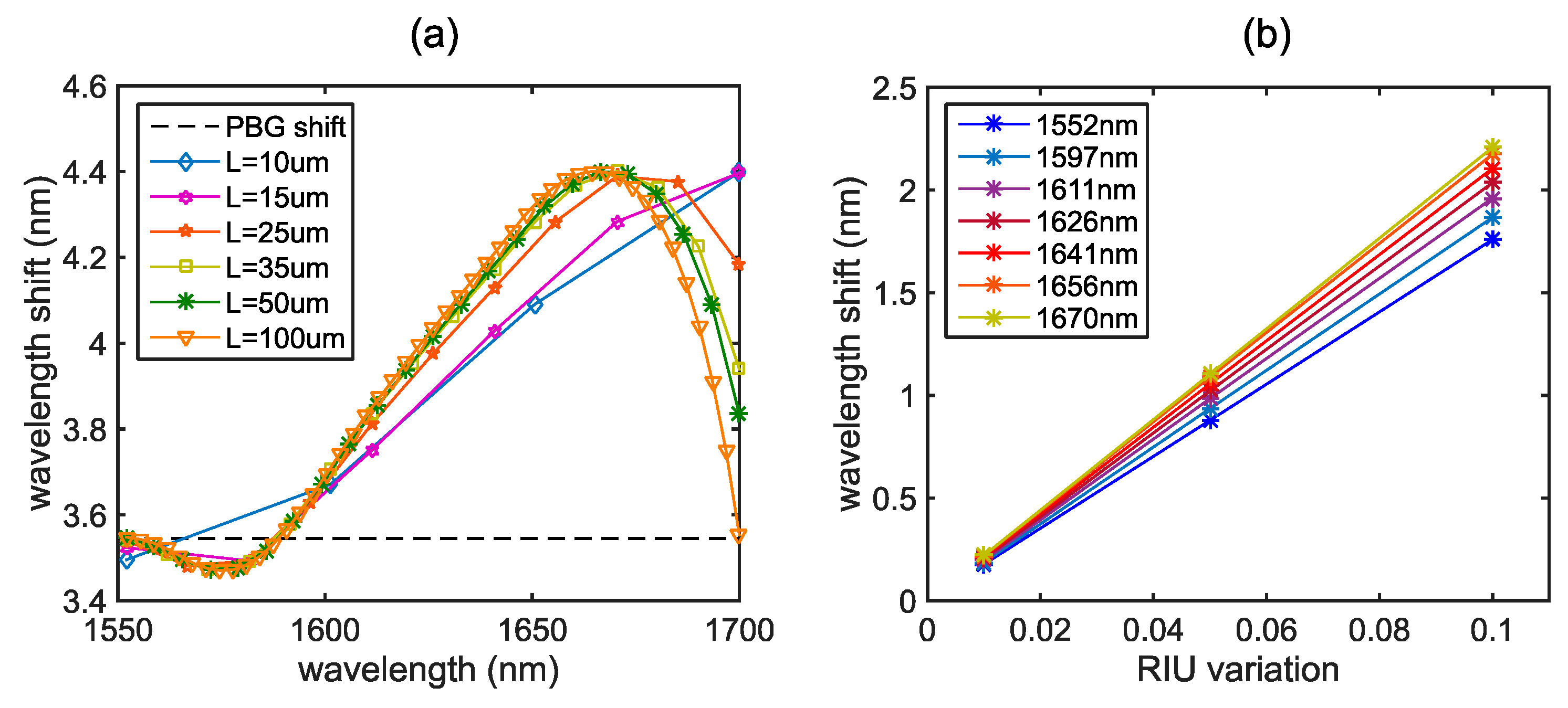
3.2. Phase and Wavelength Shift Based Sensing

The results that were obtained for the phase shift produced between the modes for a given RI variation are depicted in Figure 3. There is a length dependence as a consequence of higher phase shifts accumulated when the L value is increased, as described in Equation (1). However, high phase shift values are obtained for those wavelengths near the PBG edge, including short bimodal lengths. The reason of that is explained in the Figure 3b, where we can see that higher phase shifts are obtained for lower wavelengths due to the slope of the wavevector difference. Consequently, it can be seen that the phase sensitivity is directly proportional to the slope of the phase shift versus the wavelength, reaching maximum values for those regions close to the PBG edge, where the slow-light phenomenon is produced. Nonetheless, that high values of sensitivity are only available for a short range of wavelengths, expanding the bandwidth as the bimodal section length increases. Theoretically, sensitivity values of around 5000 x 2 π r a d / R I U could be obtained for lengths of 50–100 µmm, which represents a step forward the integration of that structures in small devices. These results are comparable to the bimodal waveguide sensitivity but with the advantage of using modal sections that are approximately 300 times shorter.
On the other hand, as we have previously explained, we can also measure the wavelength shift in the spectrum of the destructive interferences produced by the modes interaction. As the length of the bimodal region is increased, we produce more resonances in the spectrum for the same wavelength bandwidth, since higher phase shifts are accumulated. Figure 4a shows the spectral position of the resonances and how much they will be shifted towards higher wavelengths when a RI increment is produced. The dashed line compares the shift of the PBG edge to the rest of the interferometric resonances, reaching a maximum around 1660 nm. It is demonstrated that wavelength shifts higher than that occurring for the PBG edge can be obtained for other resonances placed at higher wavelengths, increasing the sensitivity in almost a 25%, reaching a sensitivity value of 220 nm/RIU as compared to 170 nm/RIU of the PBG edge. Figure 4b shows the linear evolution of the wavelength shift for different RI variations, and the different sensitivities obtained for each resonance.

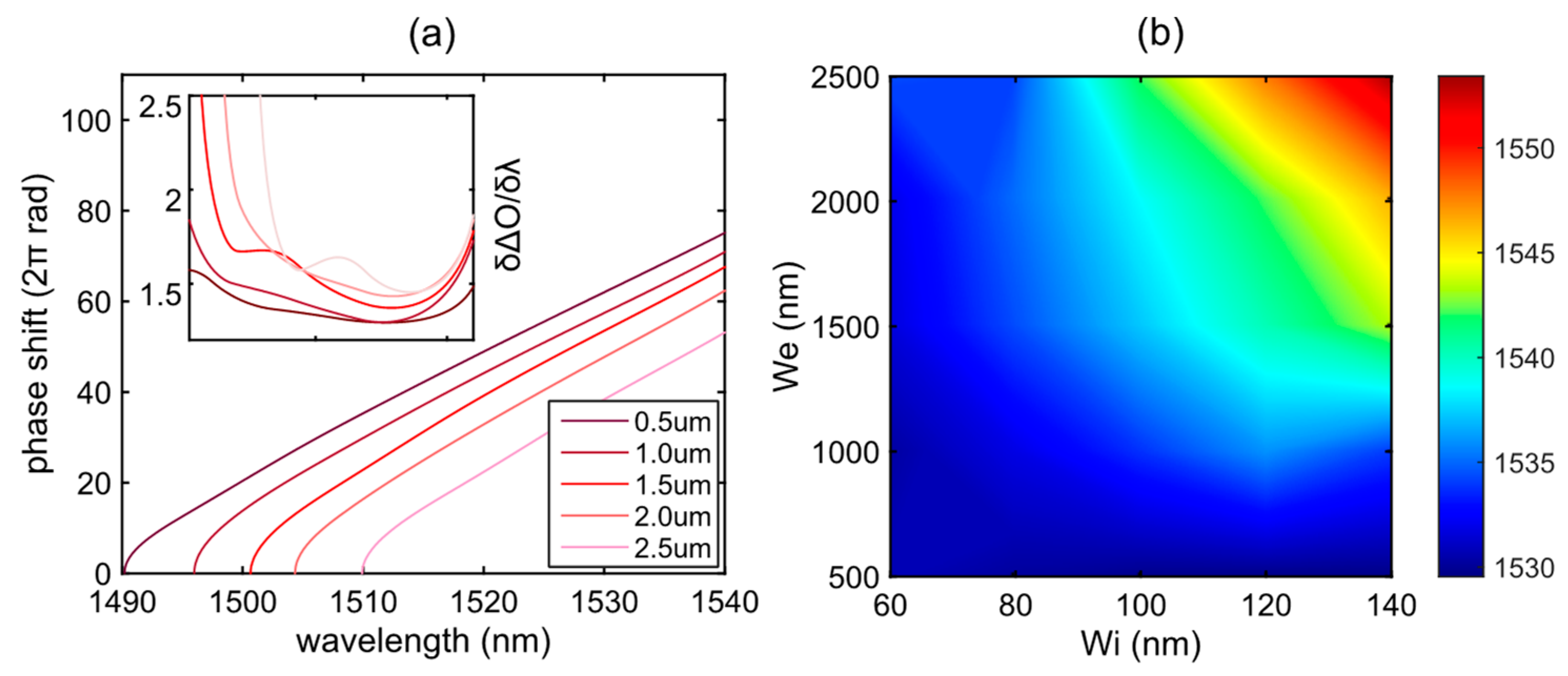
3.3. Optimization of the Sensor Parameters

As it has been demonstrated, two different sensing approaches are possible using periodic structures as modal interferometers, with each of them requiring different design features to optimize the sensor performance.
Firstly, there is a need of high phase shift slopes to reach larger phase variations near the PBG region. A parameter sweep has been carried out to simulate different working scenarios of the sensor; specifically, the transversal element length ‘we’ has been modified to check the response. Figure 5a shows the phase shift between modes for different parameter dimensions and its numerical derivative. It is clearly seen that longer lengths of ‘we’ move the PBG towards higher wavelengths while maintaining a similar slope. Nevertheless, for short lengths, there is a wider bandwidth of the bimodal region, which is desirable to increment the tolerance to fabrication deviations. Conversely, low phase shift slopes make the sensor more sensitive when tracking the resonances in the spectrum, as it was observed in Figure 4a. In this case, the sensor sensitivity is therefore inversely proportional to the phase shift derivative versus wavelength, obtaining maximum wavelength shifts for low derivative values. Figure 5b represents the wavelength where those minimums will be represented in the spectrum, which is helpful in order to tune the resonance at that point by changing the length of the bimodal region.

4. Conclusions

Two different sensing approaches have been theoretically demonstrated through MPB simulations of a one-dimensional photonic crystal. Several phase shifts for the proposed structure have been calculated in different refractive index conditions, obtaining sensitivity values of the sensor as a bimodal interferometer. In addition, the geometric design of the proposed structure represents an improvement in itself, since it only needs one lithography step in the fabrication process. This is due to the same height being used in the entire structure, unlike the bimodal waveguide, which is made of different height levels. Moreover, both sensing methods bring new improvements to the existing ones: ultra-short footprints of 50–100 um with considerable sensitivities for phase shift sensing and enhanced resonances shifts of around 25% for the spectral analysis based sensing. Overall, this new concept of a periodic-structured modal sensor offers new possibilities in using photonic crystals as interferometers, encompassing the advantages of these photonic structures as the slow-light phenomenon and the outstanding sensing benefits of the bimodal interferometers.

Author Contributions

L.T.-M. made the major part of the simulations, obtained the results and wrote the paper; J.G.-R. has supervised the entire work and the document.

Funding

European Commission founding through the Horizon 2020 Program (PHC-634013 PHOCNOSIS project) is acknowledged.

Conflicts of Interest

The authors declare no conflict of interest.

References

  1. Estevez, M.C.; Alvarez, M.; Lechuga, L.M. Integrated optical devices for lab-on-a-chip biosensing applications. Laser Photon. Rev. 2012, 6, 463–487. [Google Scholar] [CrossRef]
  2. Gavela, A.F.; García, D.G.; Ramirez, J.C.; Lechuga, L.M. Last advances in silicon-based optical biosensors. Sensors 2016, 16, 285. [Google Scholar] [CrossRef] [PubMed]
  3. Levy, R.; Ruschin, S. SPR waveguide sensor based on transition of modes at abrupt discontinuity. Sens. Actuators B Chem. 2007, 124, 459–465. [Google Scholar] [CrossRef]
  4. Sarkar, D.; Gunda, N.S.K.; Jamal, I.; Mitra, S.K. Optical biosensors with an integrated Mach-Zehnder Interferometer for detection of Listeria monocytogenes. Biomed. Microdevices 2014, 16, 509–520. [Google Scholar] [CrossRef] [PubMed]
  5. Liu, Q.; Tu, X.; Kim, K.W.; Kee, J.S.; Shin, Y.; Han, K.; Yoon, Y.J.; Lo, G.Q.; Park, M.K. Highly sensitive Mach-Zehnder interferometer biosensor based on silicon nitride slot waveguide. Sens. Actuators B Chem. 2013, 188, 681–688. [Google Scholar] [CrossRef]
  6. Prieto, F.; Sepúlveda, B.; Calle, A.; Llobera, A.; Domínguez, C.; Abad, A.; Montoya, A.; Lechuga, L.M. An integrated optical interferometric nanodevice based on silicon technology for biosensor applications. Nanotechnology 2003, 14, 907–912. [Google Scholar] [CrossRef]
  7. Levy, R.; Ruschin, S. Design of a single-channel modal interferometer waveguide sensor. IEEE Sens. J. 2009, 9, 146–153. [Google Scholar] [CrossRef]
  8. Povinelli, M.L.; Johnson, S.G.; Joannopoulos, J.D. Slow-light, band-edge waveguides for tunable time delays. Opt. Express 2005, 13, 7145–7159. [Google Scholar] [CrossRef] [PubMed]
  9. Soljačić, M.; Johnson, S.G.; Fan, S.; Ibanescu, M.; Ippen, E.; Joannopoulos, J.D. Photonic-crystal slow-light enhancement of nonlinear phase sensitivity. J. Opt. Soc. Am. B 2002, 19, 2052. [Google Scholar] [CrossRef]
  10. Castelló, J.G.; Toccafondo, V.; Pérez-Millán, P.; Losilla, N.S.; Cruz, J.L.; Andrés, M.V.; García-Rupérez, J. Real-time and low-cost sensing technique based on photonic bandgap structures. Opt. Lett. 2011, 36, 2707. [Google Scholar] [CrossRef] [PubMed]
  11. Joannopoulos, J.; Johnson, S.G.; Josua, N.W.; Meade, R.D. Photonic Crystals—Molding the Flow of Light, 2nd edition; Princeton University Press: Princeton, NJ, USA; Oxford, UK, 2008; ISBN 9780444531254. [Google Scholar]
  12. Garcia, J.; Sanchis, P.; Martinez, A.; Cuesta-Soto, F.; Blasco, J.; Griol, A.; Marti, J. Corrugated SOI Waveguide for Optimal Slow-Light Elements. In Proceedings of the 3rd IEEE International Conference on Group IV Photonics, Ottawa, ON, Canada, 13–15 September 2006; pp. 113–115. [Google Scholar] [CrossRef]
  13. García-Rupérez, J.; Toccafondo, V.; Bañuls, M.J.; Castelló, J.G.; Griol, A.; Peransi-Llopis, S.; Maquieira, Á. Label-free antibody detection using band edge fringes in SOI planar photonic crystal waveguides in the slow-light regime. Opt. Express 2010, 18, 24276–24286. [Google Scholar] [CrossRef] [PubMed]
  14. Johnson, S.; Joannopoulos, J. Block-iterative frequency-domain methods for Maxwell’s equations in a planewave basis. Opt. Express 2001, 8, 173. [Google Scholar] [CrossRef] [PubMed]
  15. Kumar, M.; Kumar, A.; Tripathi, S.M. Optical waveguide biosensor based on modal interference between surface plasmon modes. Sens. Actuators B Chem. 2015, 211, 456–461. [Google Scholar] [CrossRef]
  16. Fan, X.; White, I.M.; Shopova, S.I.; Zhu, H.; Suter, J.D.; Sun, Y. Sensitive optical biosensors for unlabeled targets: A review. Anal. Chim. Acta 2008, 620, 8–26. [Google Scholar] [CrossRef] [PubMed]
Figure 1. (a) Three-dimensional (3D) Sketch of the one-dimensional periodic structure for bimodal based sensing. The shaded color represents the bimodal sensing area of the design. (b) Band diagram for transverse-electric (TE) modes of the proposed structure in air (n = 1) and deionized water (n = 1.33) for a lattice period of a = 380 nm, waveguide width of w = 450 nm, transversal element width of wi = 100 nm, length we = 1500 nm, and height of h = 220 nm.
Proceedings 04 00020 g001
Figure 2. (a) Effective indices of both modes as a function of wavelength for a 0.02 refractive index unit (RIU) increment of the cladding refractive index (RI). (b,c) Energy density distribution in the propagation direction for modes 1 and 2, respectively, for a wavelength of 1575 nm.
Proceedings 04 00020 g002
Figure 3. (a) Total accumulated phase shifts as a function of wavelength for a cladding variation of 0.02 RIU for different lengths. (b) Wavevector difference between the two guided modes for different medium RI.
Proceedings 04 00020 g003
Figure 4. (a) Wavelength shifts for different resonances and lengths. The dashed line represents the photonic bandgap (PBG) edge shift, which is actually the same than that for the first resonance. (b) Shifts for different RIU variations. The slope of the line is equal to the sensitivity and differs depending on each resonance.
Proceedings 04 00020 g004
Figure 5. (a) Phase shift for different ‘we’ dimensions in a 1.33 RIU environment and for a given bimodal length of L = 25 µm. The inset shows the numerical derivative of the phase shift for the same range of wavelengths. (b) Colormap of the wavelengths (in nm) where minimum derivative values are obtained.
Proceedings 04 00020 g005

