Abstract
This paper presents the spring drive launcher for Unmanned Aerial Vehicle or UAV. Due to the absence that the UAV required large area for taking-off. However, to achieve the solution for this problem, we design spring drive launcher to bring the UAV up to the sky. The launcher allows the user to exceed the limit of take-off area and gives the highest initial velocity as possible. The research consists of the related theories which are Mechanical design, Engineering drawing, and Aerodynamic principles. Spring Drive launcher will be assembled by basic materials that must be made in order to get the prototype to be tested for achieving the goal. The results of the launcher will generate the constant force exerting on the launched UAV so it will reduce the risks for launching UAV multiple times. Besides the research can be carried on for the one who has the interest on the Spring Drive launcher.
1. Introduction
Nowadays, the UAV are widely used for various missions such as military, agriculture, and surveying the area from aerial photography. This does not require an airplane which has a high cost to take the plane to take off in which the area exploration is possible easily and conveniently to be observe. It is well-known for its Quad-Rotor UAV, with limitations as can fly at a distance that is not far. So, if the author wants to perform missions such as large-area exploration or a target area that is far from the launched point then it is necessary to use fixed-wing UAV. By its features in which it is small and has lightweight, as a result it can be launch by hand but the distance must not far away. For the exploration at further distances, a larger UAV is needed in which the wing size is about 2.5 m and weights are approximately 5 kg or more [1,2] (see Appendix A).
Launching by hand can be failed or not possible at some instance. In the absence of a runway, it is necessary to use a launcher to launch them. By the process of creating the instrument to be completed and can be used in real missions, so the author begins with considering various specifications. A parameter begins with the shortest distance to be launched and choose to use springs as energy storage devices for launching the UAV with acceleration from a standstill state until the velocity is equal to or greater than the stall velocity. The mechanisms must be safe and easy to proceed the procedure. For part of creating workpiece is the part that takes the most time because it needs to be adjusted or modified for better performance. As a result, the improvements or application for larger UAV can be made for further observations [1,2].
2. Related Theories and Calculation
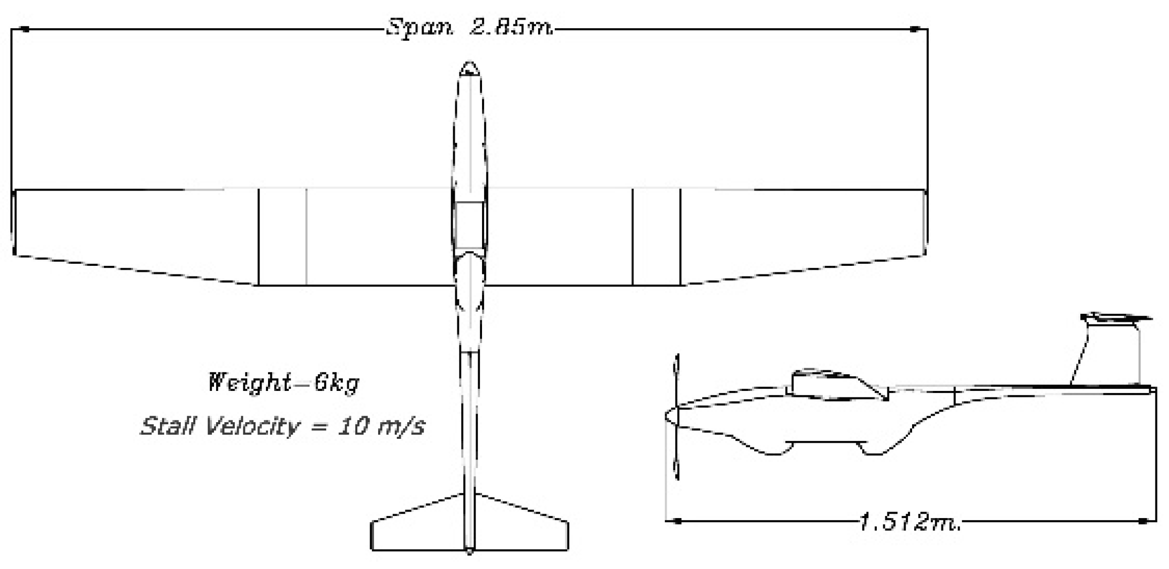
The goal is to use the force to move UAV mass in the distance specified from the standstill until the desired speed is as follows (see Figure 1) [1].
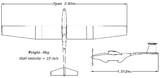
Figure 1.
UAV weight and size.
See Figure 2.
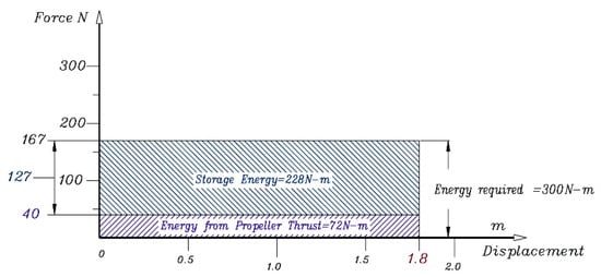
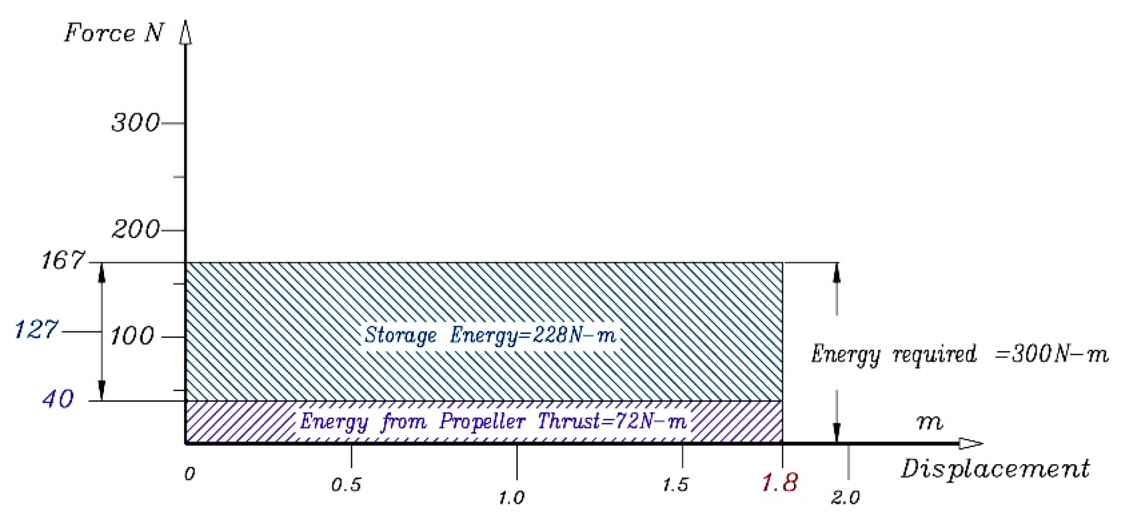
Figure 2.
Force VS. Displacement graph relative with energy required.
Figure 2.
Force VS. Displacement graph relative with energy required.
Storage energy from spring with pulley system (see Figure 3).
Maximum force acting by spring (with pulley) .
From the pulley system (see Figure 4).

Figure 3.
Force VS. Displacement graph relative with energy from spring = storage energy.
Figure 3.
Force VS. Displacement graph relative with energy from spring = storage energy.
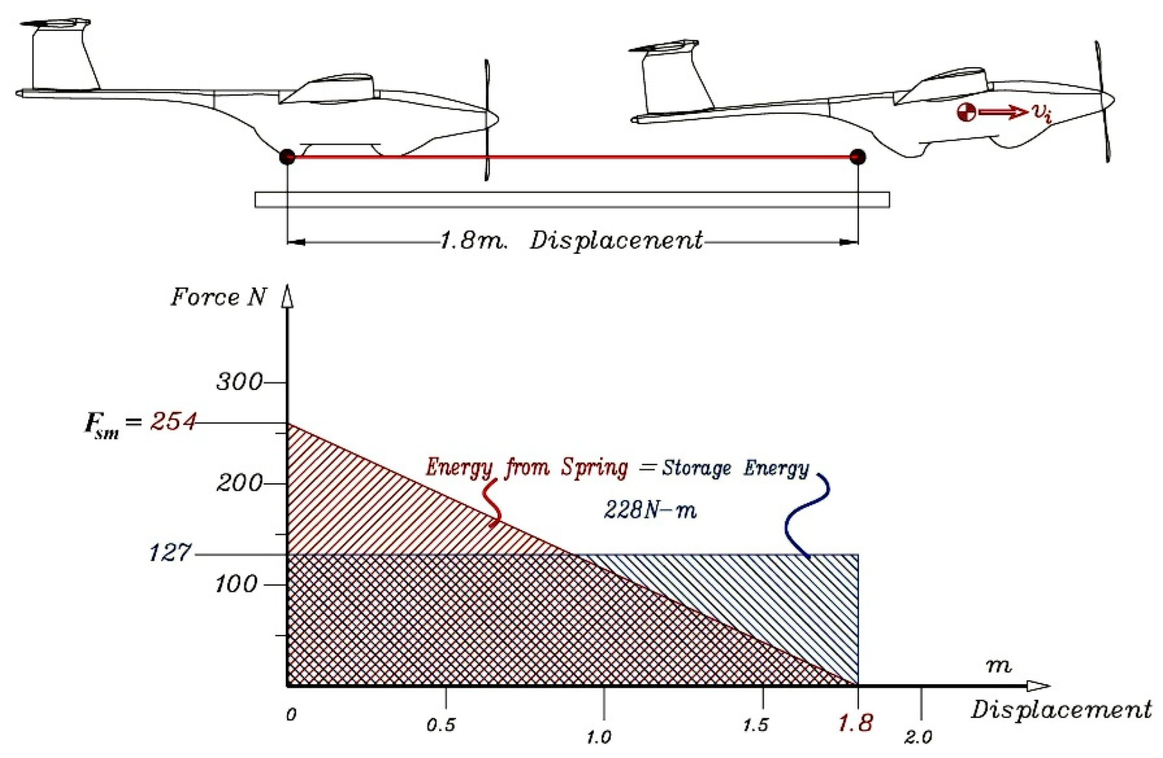

Figure 4.
Pulley system and spring displacement with power screw.
Figure 4.
Pulley system and spring displacement with power screw.
Force acting on spring set (3 springs) with pulley (by hand) =
Maximum force required = Four times of
That mean a knob can be rotate with force by hand is less than . By the spring constant of a parallel spring arrangement (see Figure 4) the effective spring constant of the parallel combination is [1,2]:
Then
Spring was bought from the market
Then
This can be concluded that all the springs from the market are proper for this job.
3. Design and Drawing
The design is based on the following: strong, cheap, durable, easy to process, safe, compact, and easy to transport (see Appendix A).
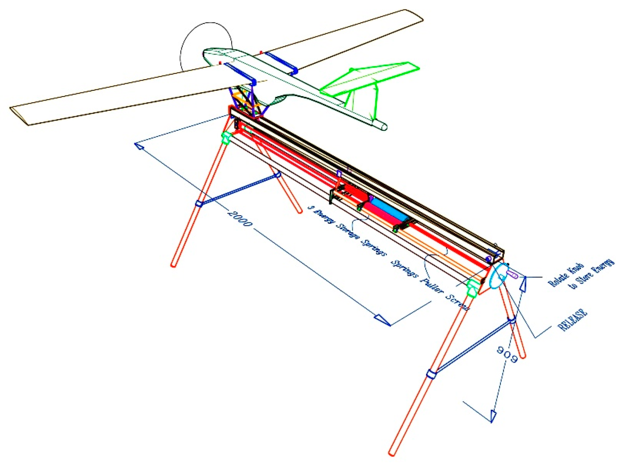
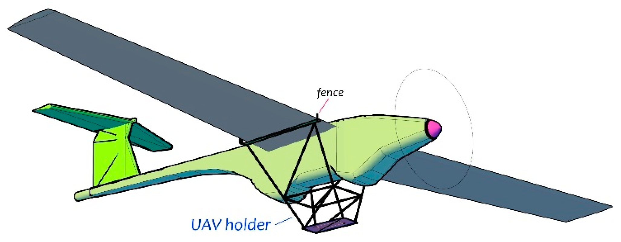
Partial design for UAV mounting and sliding along rails it is necessary to consider which part of the UAV should be held. Figure 5, Figure 6 and Figure 7 shows the mounting position and the fence prevent UAV from moving ahead while the slider has not been released. The rail can be considered very short as it need to use a lot of force for getting speed in the short distance. But the advantage is that the launcher is small and easy to move. Last but not least, the energy accumulation method by using the power screw rotation to pull the spring make its work efficiently [1].

Figure 5.
Showing the structure and components of a Spring-drive UAV launcher.
Figure 6.
(a) Shows fence while blocking and (b) releasing when slider starts moving [1].

Figure 7.
Noticed that the fence prevents movement before releasing when the propeller starts to spin.
4. Conclusions
The Spring Drive UAV Launcher can be called a useful instrument for exceeding the limits of large take-off area. However, there must be some improvement and process for making it have better efficiency. In the future, the utilization of UAV will be increased in which it can see from the various missions that require UAV nowadays.
On the other hands, the author believes that the Spring Drive UAV Launcher will be needed by the organizations that rely on the UAV. Also, the development of launcher for the large UAVs are still required for having a modification of the performance. The benefits that will get from the building launcher are also saving money that must be bought from abroad. The bungee type UAV launcher is now available for sale however most of it is a type of rubber used for lightweight UAV while the larger size comes with the expensive kits. As a result, having the UAV launcher can be used in many fields for making an observation so, the adjustment can still be made for future workspaces.
Appendix A
This section is an example of a test and practical use of the Spring-drive UAV launcher.
Figure A1.
(a) UAV initial velocity record by application in mobile phone. (b) Releasing the UAV from the Spring-drive UAV launcher.
Figure A1.
(a) UAV initial velocity record by application in mobile phone. (b) Releasing the UAV from the Spring-drive UAV launcher.
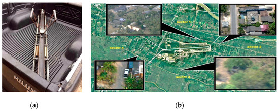
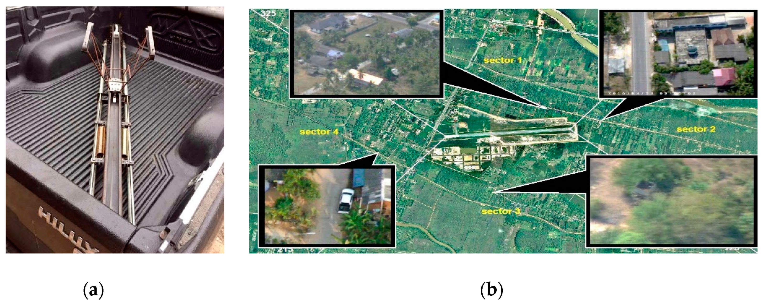
Figure A2.
(a) Spring-drive UAV launcher was designed for compact size, easy to transport. (b) Aerial photography mission in Pattani Province.
Figure A2.
(a) Spring-drive UAV launcher was designed for compact size, easy to transport. (b) Aerial photography mission in Pattani Province.
References
- Anderson, J.D., Jr. Introduction to Flight, 4th ed.; McGraw-Hill International: New York, NY, USA, 2000. [Google Scholar]
- Ruina, A.; Pratap, R. Introduction to Statics and Dynamics; Oxford University Press: Oxford, UK, 2002. [Google Scholar]

© 2019 by the authors. Licensee MDPI, Basel, Switzerland. This article is an open access article distributed under the terms and conditions of the Creative Commons Attribution (CC BY) license (http://creativecommons.org/licenses/by/4.0/).