1. Introduction
Development of new materials for high-performance power sources is one of the most frequent tasks in modern material science. For some applications, such as nanodevices, smart cards, microchips with integrated power supplies, and some medical implants, thin films power sources are the only ones that can be applied. Li-ion batteries (LIBs) are widely used in high energy density applications such as portable electronics, electric vehicles, and drones [
1]. Thanks to their high energy density and cycle life, the LIB electrochemical system is considered for the fabrication of thin film power sources [
2].
To implement thin film LIBs, it is necessary to develop and use a reliable and successful technology for their production. The most significant is the method of obtaining thin-film electrodes. Among the variety of methods, the atomic layer deposition (ALD) actively used in microelectronics [
3] should be noted. ALD deserves specific attention due to its unique features, such as its good conformity and the absence of pinholes and defects, its high precision in thickness and composition controllability, and an ability to deposit high quality coatings both on planar and on complex three-dimensional substrates with a high aspect ratio [
4,
5]. The ALD technology is based on a sequence of chemical reactions of gaseous reagents with the substrate separated in time by inert gas purges, which makes the self-limited growth of films possible [
4,
5].
Tin oxide thin films as an anode is regarded as one of the perspective materials for LIBs due to safety, cycle life and high specific discharge capacity (theoretically—1491 mAh/g) [
6,
7]. The properties of tin oxide can be improved by its lithiation.
Lithium aluminum oxide possesses a relatively high Li-ion conductivity and can be regarded as a possible candidate as an electrolyte of a solid-state power source.
In the present publication, we communicate the results of synthesis via the ALD of lithium oxide, tin oxide, lithium–tin oxides, lithium–aluminum oxide and lithium–tin oxide.
2. Materials and Methods
Monocrystalline silicon (100) substrates (20 × 20 mm) and 316SS stainless steel plates, 16 mm in diameter, were used as substrates. Before deposition, silicon and stainless-steel substrates were washed in an ultrasonic bath in acetone and then in deionized water for 10 min. After the cleaning procedure, the substrates were dried in an inert gas atmosphere.
Atomic layer deposition was carried out with the use of a commercial “Picosun R-150” setup in the laboratory “Functional Materials,” SPbPU. Lithium hexadimethyldisilazide (LiN[(CH
3)
3Si]
2—LiHMDS), Tetraethyltin (Sn(C
2H
5)
4—TET), trimethyl aluminium (TMA), water, ozone, and remote oxygen plasma (2500–3000 W, frequencies 1.9–3.2 MHz) were used to deposit films. The maintained temperatures during the ALD process for reagent vessels were as follows: TET—65 °C; LiHMDS—130–170 °C; TMA—25 °C. The excess of precursor was purged (pulse time 4–6 s) with nitrogen (99.9999%) before the counter-reactant was introduced. The synthesis was conducted at low pressure—8–12 hPa. Reactor temperature varied in the range of 200–300 °C. The denotation of samples and synthesis conditions are presented in
Table 1.
The notations of the samples used in the article can be decrypted by example—H2O(500): the substrate was placed in the chamber heated to the given temperature then 500 cycles of synthesis was conducted. Each cycle consists of four consequently performed stages LiHMDS treatment, a nitrogen purge and evacuation, water vapors treatment, a nitrogen purge and evacuation.
The growth rate was calculated based on the number of cycles and the thickness of the films, which was determined by spectral ellipsometry (SE). The ellipsometry setup “Ellips-1891 SAG” (Novosibirsk, the Russian Federation) ensured the accuracy in determining the thickness of films equal to 0.3 nm in the film thickness range of 1–100 nm. The measurements were carried out at 5–9 points of the support surface. X-ray photoelectron spectra (XPS) were registered with the use of a “Thermo Fisher Scientific Escalab 250Xi” spectrometer. The samples were excited by Al Kα (1486.7 eV) X-rays in a vacuum of 7 × 10⁻⁸ Pa. The sample charging was automatically compensated. The binding energy scale was referenced using the C 1s carbon line (284.8 eV). The depth profiles of elemental concentrations were examined by time-of-flight secondary ion mass spectroscopy (TOF SIMS 5 instrument, ION-TOF GmbH, Münster, Germany). Depth profiles of the elements were recorded in dynamic SIMS mode using the primary ion gun (Bi+ at 30 keV energy and 3.1 pA measured sample current, area 70 × 70 µm) for analysis and Cs (0.5 keV, area 120 × 120 µm) for sputtering. Both positive and negative ion modes were used. The total analysis (sputtering) time for each mode was 4 min.
3. Results and Discussion
3.1. Growth Per Cycle
The Li–O films were deposited with two pairs of precursors: LiHDMS/H2O vapors and LiHDMS/O2 plasma. Despite the method of synthesis, the deposited films had changed their color during contact with the air atmosphere. The change of color may have been caused by the augmentation of film thickness and their composition after reaction with water vapors present in the air. In order to hinder this adverse reaction, the samples were placed in an argon-filled (H2O content less than 10 ppm) Glove box (VGB-6, MTI). The samples were withdrawn immediately before carrying out measurements. To prevent a hydration reaction, an alumina thin layer was deposited via ALD.
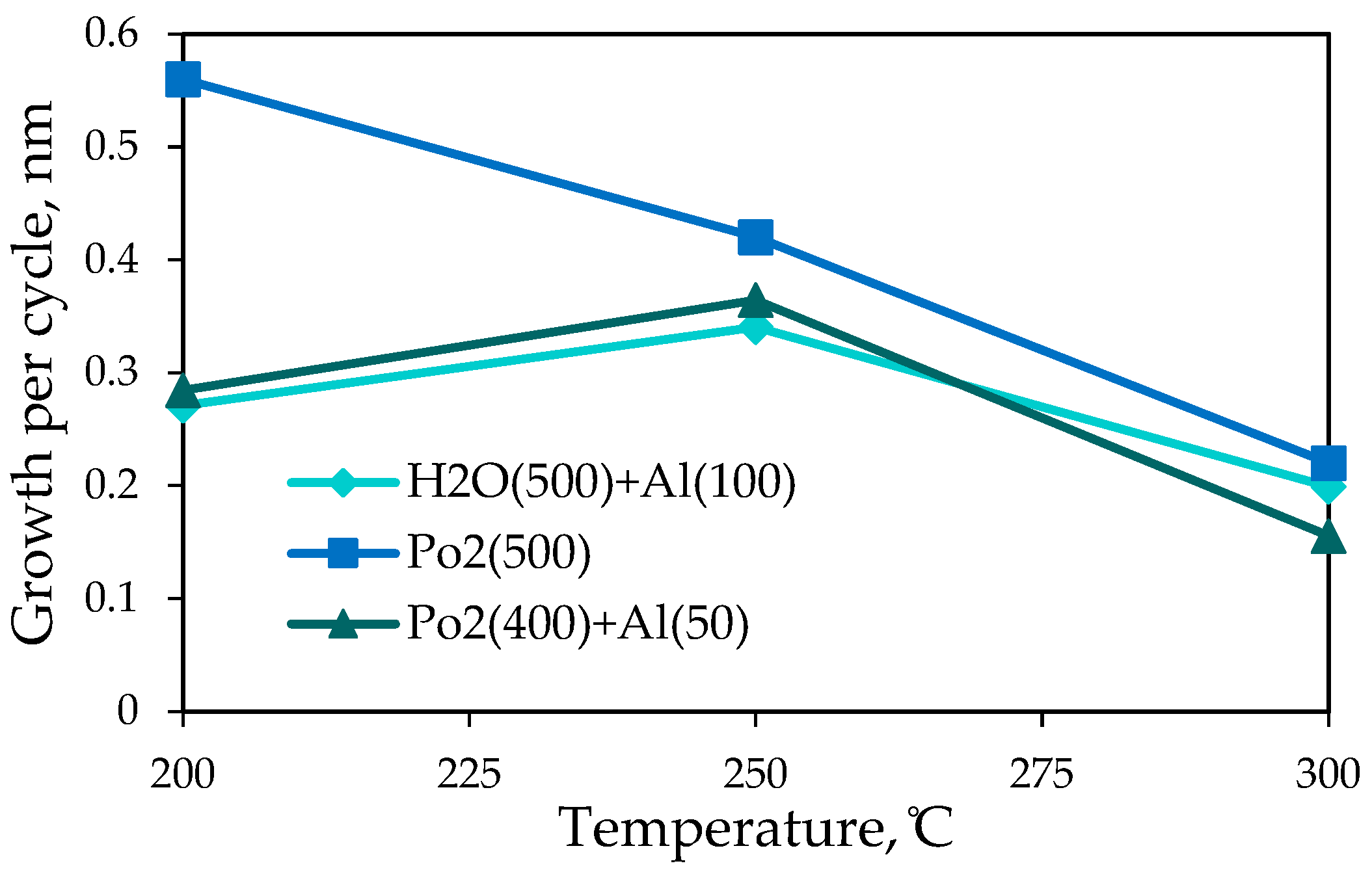
The effect of temperature on the growth rate of Li–O films and Li–O modified by alumina are shown in
Figure 1. For the films Li–O deposited with the use of oxygen plasma, the growth rate diminishes with the increase in temperature. The same influence of temperature was observed earlier in SnO
2 films [
8]. The growth rates of H
2O(500)+Al(100) and Po2(400)+Al(50) films are similar. For both samples, the maximum growth rate was observed at 250 °C and may have been caused by secondary processes [
9,
10] that lead to nanocrystal formation and/or formation lithium aluminate. The minimal values of growth rates (0.16–0.22 nm per cycle) were observed for the synthesis at 300 °C and are consistent with growth rates observed in the ALD process [
4,
5,
8].
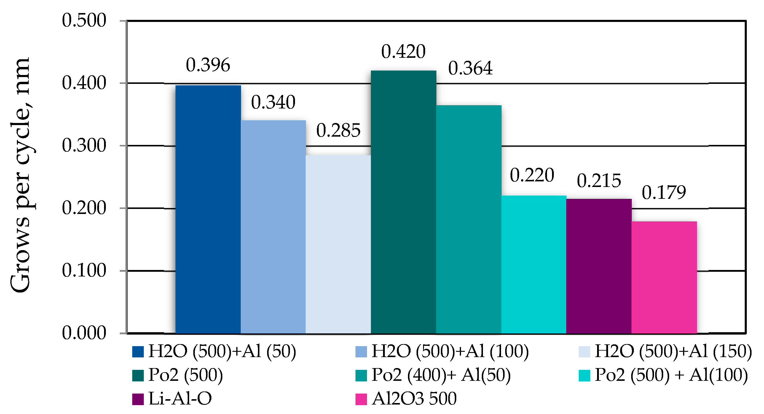
The growth rates for films of different compositions deposited at 250 °C are presented in
Figure 2. The growth rates calculated for Li–Al–O and Al
2O
3 are consistent with values determined for films deposited by the ALD process [
4]. The estimated average growth rate for Li–O films modified by alumina is higher than theoretical values and it diminished with the increase in the number of TMA/H
2O treatment cycles. It is possible that in our case the deposited film of alumina did not fully protect the Li–O film. Assuming that the alumina growth rate is constant, one can conclude that the use of LiHMDS/H
2O provides a higher growth rate than LiHMDS/O
3 precursors. It is likely that 250 °C is not warm enough for a full desorption of water molecules from a Li–O film surface, and part of the film deposits according to a chemical vapor deposition process [
11]. Thus, in order to avoid an uncontrollable growth of films, a Li–O water-free process should be used.
The influence of synthesis conditions on the growth rate of SnO
2 was investigated in our previous paper [
4]. The approximate value of the growth rate of films obtained at 250–300 °C varied from 0.06 to 0.09 nm per cycle. The thickness of the obtained Li–Sn–O films (300 °C, 300 cycles) varied in the range 27.4–30.4 nm, so the growth rate varied in the range 0.09–0.1 nm per cycle.
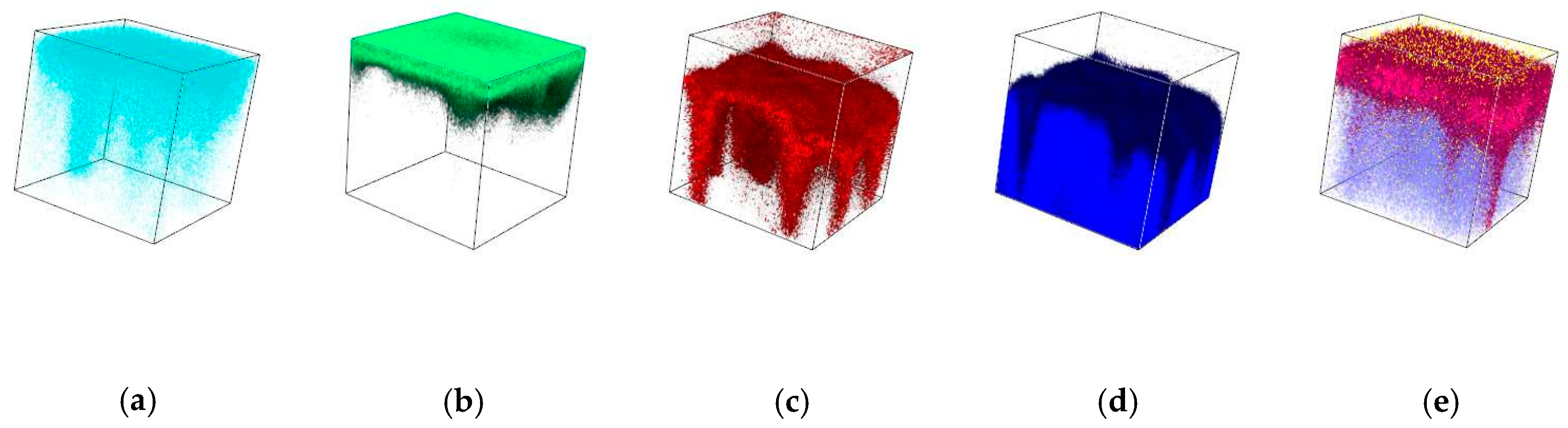
3.2. Depth Distribution of Elements
The depth distribution of elements was studied with the use of TOF SIMS. The analysis of Li–O films modified by alumina (Po2(500)+Al(100)) was carried out in positive (
Figure 3a,b) and negative (
Figure 3c–e) modes. In positive mode, at the beginning of analysis (external surface), the lithium ions were fixed. With the increase in sputtering time, the concentration of lithium diminished, and after 2 min it was close to the value of error. On the contrary, the concentration aluminum ions increased with the sputtering time. In negative mode, at the initial time of sputtering, the LiOH
− was detected, followed by AlO
−, OH
−, and O
−. Despite the attempt to cover and protect the Li–O film, it was still present on the external surface of the sample. Alumina seemed to diffuse through the Li–O film during synthesis, or lithium seemed to diffuse to the external surface. Thus, the deposited alumina film did not protect the Li–O film, and the estimated increased growth per cycle was due to its hydration.
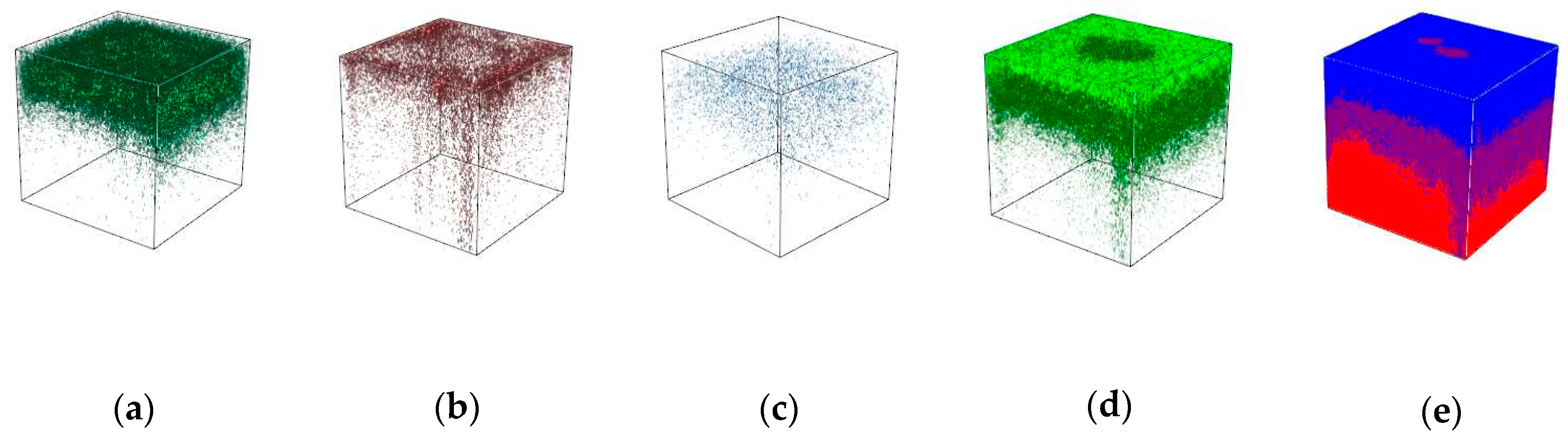
According to the TOF SIMS analysis (negative mode) of the Li–Sn–O film, the anions containing Li, Sn, and O were present in the film. Lithium (
Figure 4a,b) was distributed uniformly over the coating thickness. LiOH
- was mainly present at the external surface of the investigated film. Tin anions were found in the inner layers of the film, but their quantity was much lower than that of anions containing lithium. The Li precursor likely interacts more actively with the surface groups than does the Sn precursor, and this results in a lower quantity of Sn in the film. Thus, in order to increase the quantity of Sn in the film, more long pulses, or a greater number of pulses, are required.
3.3. Chemical State of Surface Atoms
XPS analysis of the deposited films showed the presence of peaks with a binding energy corresponding to O 1s, C 1s Li 1s, and Al 2p for Li–Al–O and O 1s, C 1s Li 1s, and Sn 3d for Li–Sn–O films. Maximums with a binding energy corresponding to Si 2p and N 1s were not found; therefore, in the lithium precursor, these elements were not present in the external layers of the deposited films. The unsymmetrical from of the O 1s peak and the additional maximum in the area of low binding energy (523 eV) may have been caused by the presence of hydroxyl groups or by organic impurities containing oxygen. The registered additional maximum in the region of 280 eV (C 1s) may also signify the presence of organic impurities.
4. Conclusions
Thin films of different compositions (Li–O+Al-O, Al-O, Li–Al–O, and Li–Sn–O) were deposited via ALD. The minimal growth rate per cycle, which is close to the reported values intrinsic of ALD, was observed at 300 °C. Modification of Li–O films by alumina (less than 100 cycles of treatment) may hinder the hydration of the surface but cannot prevent it. When water is applied as a second precursor for Li–O film deposition with the use of LiHMDS, the growth rate is higher than in the case of the use of oxygen plasma. The elemental analysis of Li–O films modified by alumina showed that lithium is present on the external surface, whereas alumina is found in deep layers of the film. This observed phenomena may be caused by the diffusion of lithium or aluminum. The quantity of tin in Li–Sn–O films is smaller than the quantity of lithium. More long pulses are probably required to obtain Li–Sn–O films with an equimolar quantity of Li and Sn.
Author Contributions
M.Y.M., Y.K., and D.N. conceived and designed the experiments; I.M., D.N., and M.Y.M. performed the experiments; I.M., M.Y.M., Y.K., and D.N. analyzed the data; A.P. contributed reagents, materials and analysis tools; M.Y.M. and I.M. wrote the paper; M.Y.M. and Y.K. reviewed the article.
Acknowledgments
This research was supported by the Russian Science Foundation grant (project No. 18-73-10015).
Conflicts of Interest
The authors declare no conflict of interest.
References
- Goodenough: J., B.; Park, K.S. The Li-ion rechargeable battery: A perspective. J. Am. Chem. Soc. 2013, 135, 1167–1176. [Google Scholar] [CrossRef] [PubMed]
- Chen, J. Recent Progress in Advanced Materials for Lithium Ion Batteries. Materials 2013, 6, 156–183. [Google Scholar] [CrossRef] [PubMed]
- Hwang, C.S.; Yoo, C.Y. (Eds.) Atomic Layer Deposition for Semiconductors; Springer: New York, NY, USA, 2014; ISBN 978-1-4614-8054-9. [Google Scholar]
- George, S.M. Atomic Layer Deposition: An Overview. Chem. Rev. 2010, 110, 111–131. [Google Scholar] [CrossRef] [PubMed]
- Knoops, H.C.M.; Donders, M.E.; van de Sanden, M.C.M.; Notten, P.H.L.; Kessels, W.M.M. Atomic layer deposition of nanostructured Li-ion batteries. J. Vac. Sci. Technol. A 2012, 30, 010801. [Google Scholar] [CrossRef]
- Ahmed, B.; Anjum, D.H.; Gogotsi, Y.; Alshareef, H.N. Atomic layer deposition of SnO2 on MXene for Li-ion battery anodes. Nano Energy 2017, 34, 249–256. [Google Scholar] [CrossRef]
- Winter, M.; Besenhard, J.O. Electrochemical lithiation of tin and tin-based intermetallics and composites. Electrochim. Acta 1999, 45, 31–50. [Google Scholar] [CrossRef]
- Nazarov, D.V.; Maximov, M.Y.; Novikov, P.A.; Popovich, A.A.; Silin, A.O.; Smirnov, V.M.; Bobrysheva, N.P.; Osmolovskaya, O.M.; Osmolovsky, M.G.; Rumyantsev, A.M. Atomic layer deposition of tin oxide using tetraethyltin to produce high-capacity Li-ion batteries. J. Vac. Sci. Technol. A Vac., Surf. Films 2017, 35, 01B137. [Google Scholar] [CrossRef]
- Puurunen, R.L. Surface chemistry of atomic layer deposition: A case study for the trimethylaluminum/water process. J. Appl. Phys. 2005, 97, 121301. [Google Scholar] [CrossRef]
- Koshtyal, Y.M.; Malkov, A.A.; Taulemesse, J.M.; Petrov, S.N.; Krasilin, A.A.; Malygin, A.A. Structural and chemical transformations in the products of the interaction of silica gel with vapours of TiCl4 and H2O. Appl. Surf. Sci. 2014, 288, 584–590. [Google Scholar] [CrossRef]
- Comstock, D.J.; Elam, J.W. Mechanistic Study of Lithium Aluminum Oxide Atomic Layer Deposition. J. Phys. Chem. C 2013, 117, 1677–1683. [Google Scholar] [CrossRef]
© 2018 by the authors. Licensee MDPI, Basel, Switzerland. This article is an open access article distributed under the terms and conditions of the Creative Commons Attribution (CC BY) license (https://creativecommons.org/licenses/by/4.0/).


