Proceeding Paper

Infrared Thermography for DIEP Flap Breast Reconstruction Part I: Measurements

1
Op3Mech research group, Electromechanics Department, University of Antwerp, Groenenborgerlaan 171, B-2020 Antwerp, Belgium
2
Multidisciplinary Breast Clinic, Antwerp University Hospital, University of Antwerp, B-2650 Antwerp, Belgium
*
Author to whom correspondence should be addressed.
Presented at the 15th International Workshop on Advanced Infrared Technology and Applications (AITA 2019), Florence, Italy, 17–19 September 2019.
Equality contributed.
Proceedings 2019, 27(1), 48; https://doi.org/10.3390/proceedings2019027048
Published: 3 December 2019

Abstract

:
In order to identify the exact location of a useful perforator for DIEP flap breast reconstruction, CT images are made in the pre-operative phase. The aim of this research is to evaluate if dynamic infrared thermography is a helpful tool to check and visualize the blood flow in the flap during the pre- and peroperative phase. The results will be used in order to pinpoint the usefulness of IR thermography as an alternative method for perforator mapping and flapdesign. By means of infrared thermography the blood vessel distribution and its vascularisation of the abdominal wall will be visualized. The thermal images can help to detect the correct perforator and can help to decide which parts of the flap are best perfused and can be used for the DIEP flap reconstruction.

1. Introduction

Breast cancer treatment still involves the removal of the breast in a number of cases. A reconstruction after breast amputation, preferable with autologous tissue, should always be discussed with the patient as part of the treatment. The reconstruction itself is a delicate operation because of fragile blood supply. In some cases, the surgeon selects tissue for transplantation which does not fulfil the essential requirement concerning sufficient blood supply. This results in flap failure and necrosis of the transplanted tissue. With the use of infrared thermography the blood vessel distribution of the abdominal wall and its vascularization can be visualized. Based on the information of the pre-operative ct scan and the information of the thermography, a possible better selection of the perforators of the free flap can be performed and also the design of the flap can be optimized based on the visualization of the vascularization of the perforators. The aim of this research is to check and visualize the blood flow in the flap by means of infrared thermography.
The thermal images will help to decide which parts of the flap can or cannot be used for the DIEP flap reconstruction. Currently, the assessment of the perfusion of the flap is clinically. The necrosis is only identified visually in the post-operative phase, causing additional surgery to be performed. By making use of passive infrared thermography in the pre-operative phase but also during the reconstructive operation, it is our goal to identify the cause of necrosis and diminishing all negative side-effects [1].

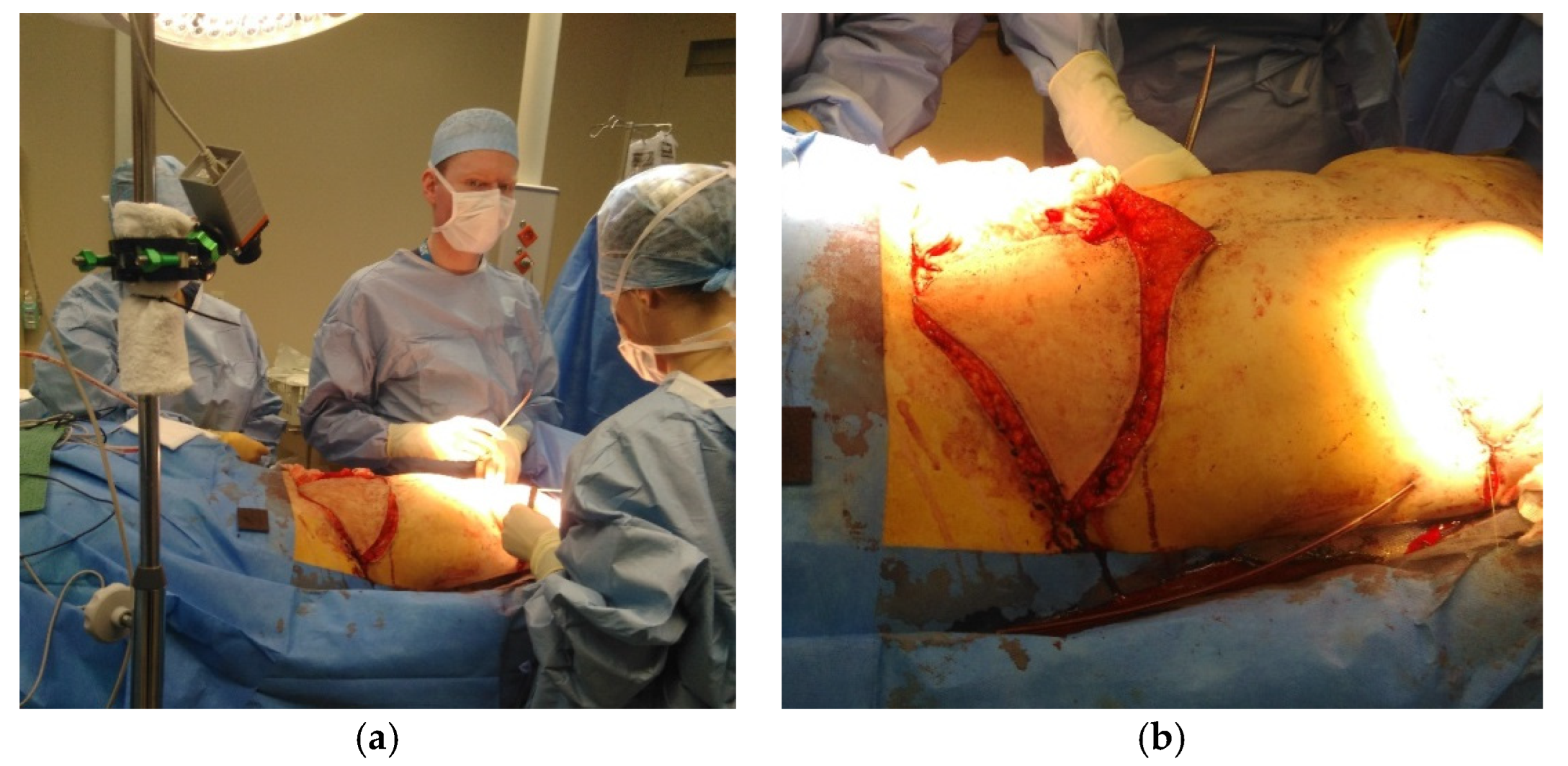
2. Methodology and Measurement Setup

In order to perform feasibility study of the use of infrared thermography during free flap surgery, the researchers were invited to attend a breast reconstruction with a DIEP-flap. They perform thermal measurements that can act as a basis for more dedicated measurements during a follow-up study. The patient underwent a unilateral breast reconstruction using the DIEP-flap technique. In this technique no fascia nor muscle is transplanted, only skin and fat is transplanted. When performing a unilateral DIEP flap both sides of the abdomen can be used for the reconstruction. Is thermography a helpful tool in order to select the perforator? Figure 1 shows an image of the measurement setup during operation. The microbolometer camera is placed on a tripod during operative surgery in order to measure the temperature evolution of the abdomen during operation. Figure 2 shows the free flap during the operation. At this stage, the flap is still connected with the two perforators. The camera used for the thermal images is a Xenics Gobi 640 microbolometer 640 × 480, NETD 30 mK, 50 Hz with 7.5–14 µm spectral range. The performed measurement during DIEP flap operation includes the passive thermography snapshot technique in combination with transient measurements at ca 6.25 Hz. The test sample is a flap, only connected with its 2 perforators. Both perforators will be clamped together but also separately in order to examine their influence on the vascularisation of the flap. The ambient temperature equals 20 °C with a humidity of 35% under stable conditions and LED illumination. The measurements were performed in operating room. The location of the chosen perforators was determined with the golden standard: CT-scan. The location of these perforators will be double-checked during operation with the use of thermography.

3. Results & Discussion

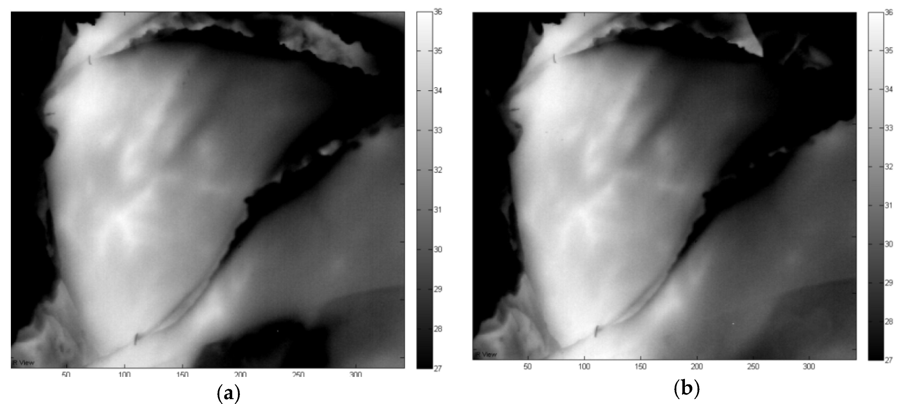
3.1. Left Flap in Rest 2 Perforators (A+B) Open

After disseccting the left flap from the abdominal wall, the blood flow is initiated at time stamp 11:55 and it is noticeable that the temperature increases and the perforators become more visible over time. This is a logic result from the blood running through both the perforators A and B. After 10 minutes, steady state conditions are achieved and the temperature profile remains stable. This is noticeable in Figure 3 where two thermal images are shown with 10 min in between both measurements. It is clear that the temperature is in steady state and that there’s little difference to be noticed between the two measurements. Both perforators togethers vascularize the flap well.

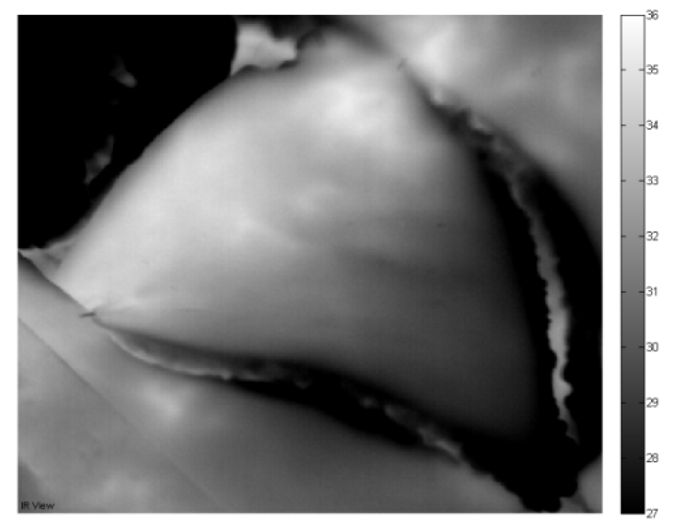
3.2. Left Flap in Rest: Vein A Closed and Vein B Open

When opening perforator B but keeping perforator A closed, one can notice the region that is perfused by perforator B (Figure 3). The bigger this area is, the more important perforator b is with respect to suitable perforator for the DIEP flap breast reconstruction. In Figure 4, perforator B is opened (clamp removed) at time instance 12:35 PM and the evolution is tracked during 15 minutes. The effect of opening perforator B can be visualized by looking at the thermal measurement at different time instances. From Figure 4, one can notice that the bottom region of the flap cools down but the top region remains at a higher temperature. In addition, the perforators are not clearly visible by opening perforator B. The limited predictive quality of these thermal measurements will be compared with the inverse situation when opening perforator A while keeping perforator B closed.

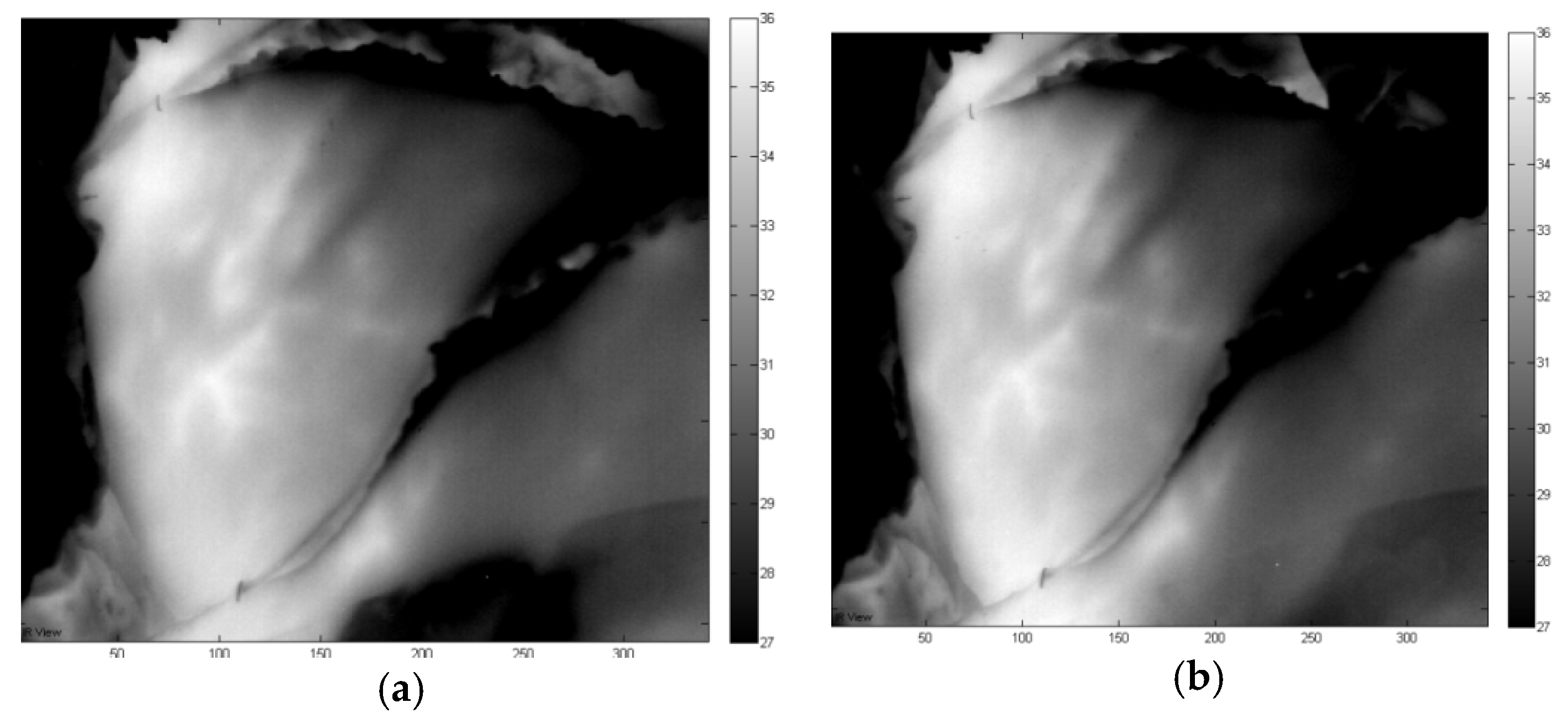
3.3. Left Flap in Rest: Perforator A Open and Perforator B Closed

When opening perforator A but keeping perforator B closed, one can notice the region that is perfused by perforator A. The bigger this area is, the more important perforator A is with respect to suitable perforator for the DIEP flap breast reconstruction. In Figure 5, perforator A is opened (clamp removed) at time instance 12:55 P.M. and the evolution is tracked during 20 min. The effect of opening vein A can be visualized by looking at the thermal measurement at different time instances. From Figure 5, one can notice that the bottom region of the flap cools down but the top region remains at a higher temperature, which was also detected in Figure 4. The temperature in top region slowly decreases, the temperature in largest bottom region of the flap remains more or less stable and the perforator become clearly visible. On the contrary to Figure 4 with perforator B open, the perforators are now clearly visible by opening perforator A. From these thermal measurements, one can expect that perforator A open causes a better perfusion than perforator B open. This might lead to the conclusion that perforator A is a “better” perforator than vein B.

4. Conclusions

From the presented initial results based on a single test sample, we can conclude that infrared thermography offers extra information on the location of the perforators and its vascularization. Dynamic Infrared Thermography can be a promising alternative in future to CTA for preoperative perforator mapping in DIEP breast reconstruction. These results are in accordance with the published results by De Weerd [2]. Further investigation on more patient samples will reveal how far one can go with infrared thermography for identifying perforators in an accurate manner. Also, during operation, IR thermography can identify which zone of the free flap is to be used for the reconstruction, depending on the level of bleed though in the flap.

Funding

This research was funded by the University of Antwerp and the Institute for the Promotion of Innovation by Science and Technology in Flanders (VLAIO) via support for the TETRA project, “SINT: Smart Integration of Numerical modeling and Thermal inspection,” project number HBC.2017.0032. The researchers received funding from the Antwerp University IOF-council through project PSID-34924 entitled “Fast Broadband Lock-In Thermography for Fragile Structures Using System Identification.”

Acknowledgments

The authors would like to thank Ralv Lundahl and the UZA medical staff for the support on the preliminary measurements.

Conflicts of Interest

The authors declare no conflict of interest.

References

  1. Weum, S.; Mercer, J.B.; de Weerd, L. Evaluation of dynamic infrared thermography as an alternative to CT angiography for perforator mapping in breast reconstruction: A clinical study. BMC Med. Imaging 2016, 16, 43. [Google Scholar]
  2. De Weerd, L.; Weum, S.; Mercer, J.B. Dynamic Infrared Thermography (DIRT) in the preoperative, intraoperative and postoperative phase of DIEP flap surgery. J. Plast. Reconstr. Aesthet. Surg. 2012, 65, 694–695. [Google Scholar]
Figure 1. This is a Figure 1: Measurement setup during operation (a) and flap during DIEP flap operation (b).
Proceedings 27 00048 g001
Figure 2. Thermal measurements with left flap in rest and 2 perforators (A+B) open Measurement setup during operation (a) and free flap during DIEP flap operation (b).
Proceedings 27 00048 g002
Figure 3. Thermal measurements with left flap in rest and 2 perforators (A+B) open Measurement setup during operation (a) and free flap during DIEP flap operation (b).
Proceedings 27 00048 g003
Figure 4. Thermal measurements with left flap in rest and vein B open.
Proceedings 27 00048 g004
Figure 5. Thermal measurements with left flap in rest and perforator A open.
Proceedings 27 00048 g005

