Proceeding Paper

Thermographic Monitoring of Laser Cutting Machine †

1
CNR-ITC, C.so Stati Uniti 4, 35127 Padova, Italy
2
University of Trento, Dipartimento di Ingegneria Civile Ambientale e Meccanica, via Mesiano 77, 38123 Trento, Italy
*
Author to whom correspondence should be addressed.
Presented at the 15th International Workshop on Advanced Infrared Technology and Applications (AITA 2019), Florence, Italy, 17–19 September 2019.
Proceedings 2019, 27(1), 28; https://doi.org/10.3390/proceedings2019027028
Published: 23 September 2019

Abstract

:
Computer Numerical Controlled (CNC) laser cutting tools are developing as an alternative to conventional cutting systems thanks to increased accuracy, non-contact processing, higher productivity, less energy demand. An IR camera is utilized to monitor the laser cutting process of a steel plate. Even though the process is very complicated an analytical solution of the temperature field generated on a slab by a point source moving along one direction of the plate surface is provided in order to interpret the temperature field experimentally obtained by the IR camera.

1. Introduction

Computer Numerical Controlled (CNC) laser cutting tools are developing as an alternative to conventional cutting systems thanks to increased accuracy, non-contact processing, higher productivity, less energy demand. They are used both in producing complicated cutting paths in metallic sheets of steel, copper, aluminum etc. and to cut large tubes to be combined in large structural applications. State of the art of such systems are made of a diode generator device that produces the laser beam either in Continuous Wave (CW) or modulated with frequency around some kHz. Typical wavelength is around 1064 nm and average power from 1 to several kW. The beam is launched through an optical fiber to a focusing head mounted on a 2/3-axis movement (sometimes more). Once focused, the beam diameter is around 100 μ m, with an area of 2.5× 10 9 m 2 and a surface power density of the order of 1000 GW m 2 . The head and the metal part to be cutted, are confined within a shield for the safety of the operator. All the system is driven remotely by a computer [1].
Notwithstanding the many interesting characteristics of such systems, some issues had been arosed regarding the effects of the high temperature exposition (that in the cutting region reaches the melting of the metal) and the possible degradation of the mechanical properties of the manufact even though in a limited region around the cutting boundary. Evidently, such a concern is of a modest interest in case of decorative applications like the manufacturing of plaques, logos etc., while it becomes of the highest importance when structural applications are considered.
Sheng [2] proposes an analytical solution of the energy balance at the cutting surface to determine the Heat-Affected Zone (HAZ) on stainless steel 304. Barenyi [3] measured the tensile strength and yield strength of high strength Armox steels after cutting by laser, plasma and water jet and concluding that water jet, due to non heating cutting method, is better than laser, that on its turn is better of plasma technology. Petkovic [4] analyses the influence of laser power, cutting speed and gas pressure on the HAZ by adaptive neuro fuzzy inference system and concluding that the cutting speed is the most influencial parameter on the HAZ. Miraoui [5] considers a CO2 laser cutting on low carbon steel plates and investigates the HAZ and the Melted Zone (MZ) microstructures by scanning electron microscopy, optical microscope and Vickers microhardness.
While the IR camera had been extensively used to monitor the welding process and more recently to monitor the the laser assited addiditive manufacturing processes, to the knowledge of the authors, the possibility of monitoring the temperature field during the laser cutting process is considered only by Canisius [6] that uses an IR camera to look at the surface temperature on a piece of Carbon Fiber Reinforced Polymer.
In this work an IR camera is utilized to monitor the laser cutting process of a piece of metal. Even though the laser cutting process is a very complicated phenomenon that combine phase change of the material, photothermal transformation of energy, heat transfer by conduction and radiation a simplified analytical model is proposed to determine the heat diffusion by conduction of a moving source of heat in CW and in periodic mode.

2. Materials and Methods

The experimental phase has been conducted by monitoring the cutting of a piece of carbon steel of appoximate dimension 50 cm × 50 cm and thickness 1 cm by a LT5 system at ADIGE-SYS S.P.A. manufacturing and show-room [1]. The picture of the system is shown in Figure 1.
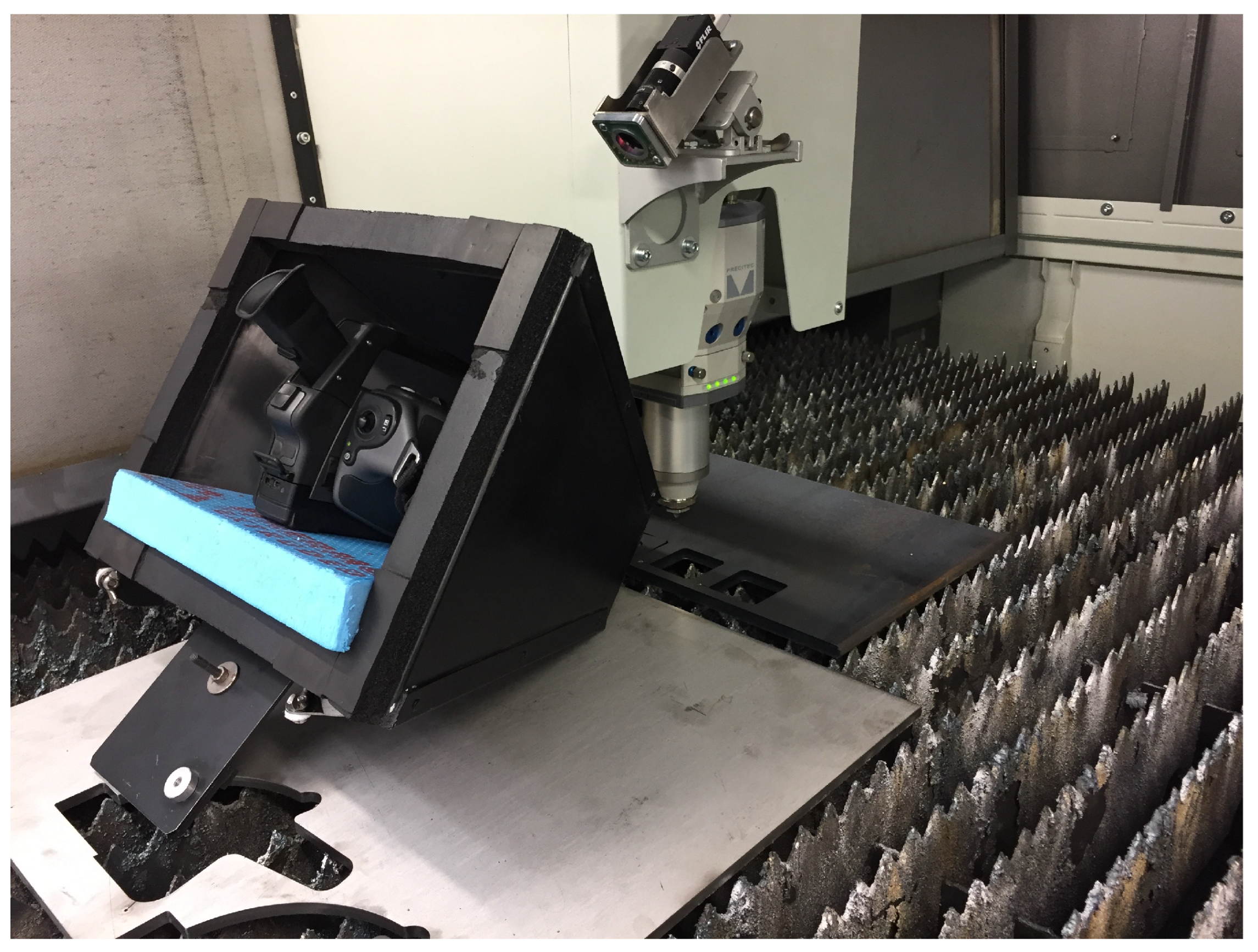
A thermal camera (FLIR SC660, spectral response 7.5 μ m–13 μ m, NETD <30 mK, 640 × 480 pixels) monitors the surface of the steel plate during the cutting process. The camera is protected with a shield to avoid the gush of molten material while it looks through a PK7 windows needed to protect the lens (sse Figure 2).
An analytical solution of the temperature field generated on a slab by a point source moving along the x axis at velocity v is given by [7]:
T ( x , y , z , t ) = q 4 π ρ c l α 0 t d t t t 1 + 2 n = 1 e α n 2 π 2 ( t t ) / l 2 cos n π z l exp [ x v ( t t ) ] 2 + y 2 4 α ( t t )
where x , y , z are the spatial coordinates of the domain (the metallic slab), whose origin is in the heat point source (the focal point of the laser beam), t is time, α , ρ , c are thermal diffusivity, density and specific heat of the metallic slab and q is the power of the laser source absorbed by the metal (the absorption coefficient must be taken into account).

3. Results

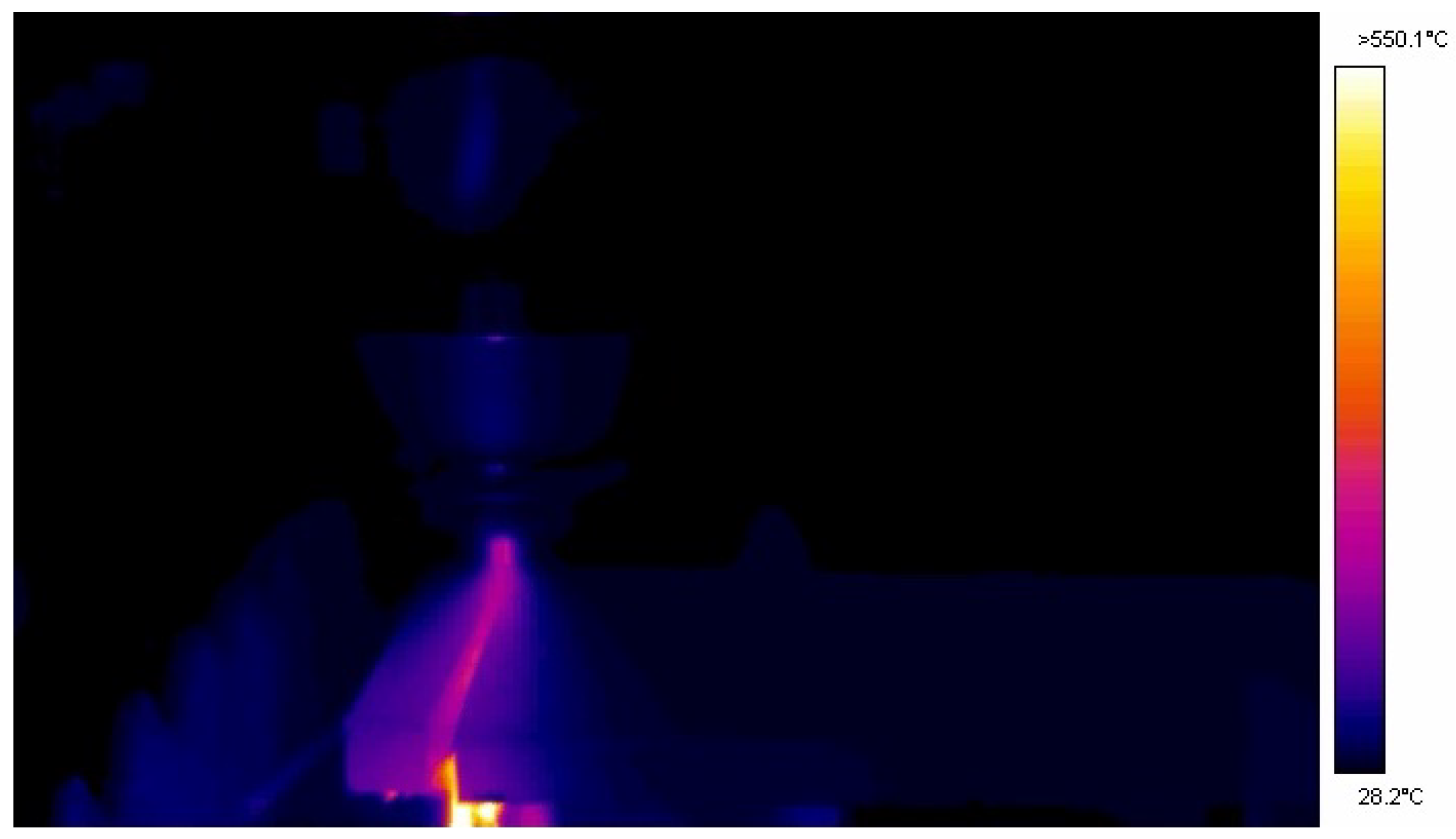
An IR image of the cutting phase with the field of temperature on the surface of the metal is shown in Figure 3.

Acknowledgments

The authors acknowledge the support of prof. Paolo Scardi and prof. Oreste S. Bursi of the University of Trento and the personal involvement in the experimental phase of dott. Alberto Valli of ADIGE-SYS S.P.A.

References

  1. LT14 Fiber. Available online: https://www.blmgroup.com/en/ (accessed on 20 September 2019).
  2. Sheng, P.S.; Joshi, V.S. Analysis of heat-affected zone formation for laser cutting of stainless steel. J. Mater. Process. Technol. 1995, 53, 879–892. [Google Scholar] [CrossRef]
  3. Barenyi, I. Changes in mechanical properties of selected uhss steels after their cutting by laser and plasma. Univ. Rev. 2014, 8, 94–105. [Google Scholar]
  4. Petkovic, D.; Nikolic, V.; Milovancevic, M.; Lazov, L. Estimation of the most influential factors on the laser cutting process heat affected zone (HAZ) by adaptive neuro-fuzzy technique. Infrared Phys. Technol. 2016, 77, 12–15. [Google Scholar] [CrossRef]
  5. Miraoui, I.; Boujelbene, M.; Zaied, M. High-Power Laser Cutting of Steel Plates: Heat Affected Zone Analysis. Adv. Mater. Sci. Eng. 2016, 2016, 1242565. [Google Scholar] [CrossRef]
  6. Canisius, M.; Oberlander, M.; Herzog, D.; Schmidt-Lehr, M.; Ploog, P.; Albert, F.; Emmelmann, C. Correlation between Temperature Field and Heat Affected Zone during Laser Cutting of Carbon Fiber Reinforced Polymers. In Proceedings of the Lasers in Manufacturing Conference 2015, Munich, Germany, 22–25 June 2015. [Google Scholar]
  7. Carslaw, H.S.; Jaeger, J.C. Conduction of Heat in Solids; Oxford University Press: Oxford, UK, 1959. [Google Scholar]
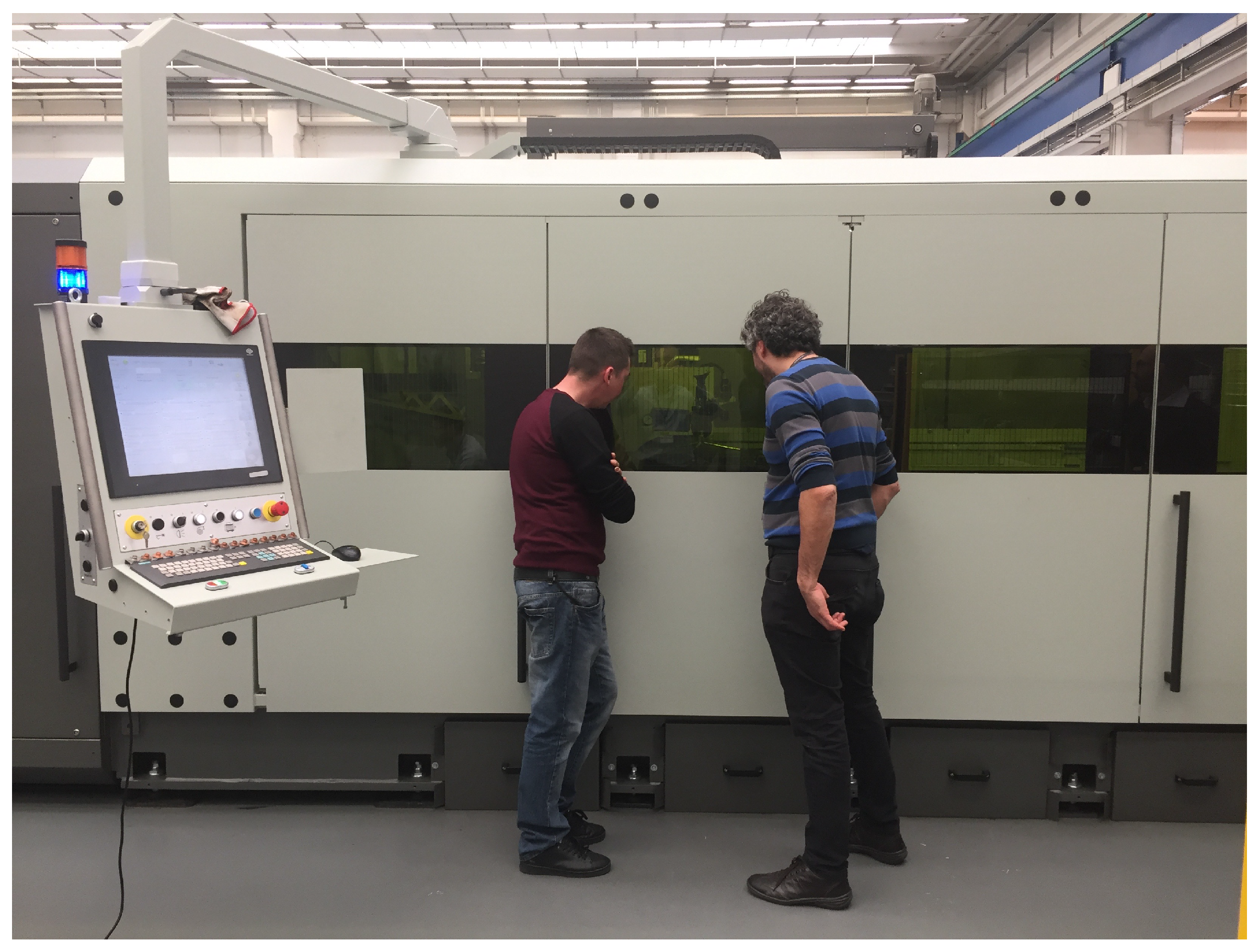
Figure 1. The LT5 Laser cutting system at ADIGE-SYS S.P.A.
Proceedings 27 00028 g001
Figure 2. The IR camera FLIR SC660 looking at the cutting process. It is protected by a metallic shield and it looks at the cutting zone through a PK7 windows to protect from the molten steel gushing from the cutting point especially during periodic pulsed mode.
Proceedings 27 00028 g002
Figure 3. IR image of the cutting phase.
Proceedings 27 00028 g003
Publisher’s Note: MDPI stays neutral with regard to jurisdictional claims in published maps and institutional affiliations.