Abstract
Wide field-of-view optical instruments based on Ritchey-Crétien telescopes have been proposed to replace narrow field-of-view scanning instruments for Earth radiation budget monitoring applications. A disadvantage of such instruments is that they are subject to significant focal plane distortion. A novel numerical focusing scheme is proposed and demonstrated using a Monte Carlo ray-trace-based simulation of the performance of a candidate instrument. Results are presented which indicate that image recovery error can be significantly reduced using the proposed algorithm.
1. Introduction
Understanding the evolution of the planetary climate requires continuous long-term monitoring of Earth-emitted (5.0 to 100 μm) and solar-reflected (0.1 to 5 μm) radiation at the top of the atmosphere. The required measurements are currently assured under the NASA-NOAA Clouds and the Earth’s Radiant Energy System (CERES) program, which uses broadband scanning instruments embarked on large multitask spacecraft placed in polar orbit [1]. DEMonstrating the Emerging Technology for measuring the Earth’s Radiation (DEMETER) is one of several concepts currently under consideration for the CERES follow-on. DEMETER would utilize a suite of Wide Field-Of-View (WFOV) nonscanning instruments embarked on small dedicated Cubesats station-keeping with traditional Earth-observing satellites [2].
One of the concepts under consideration for the DEMETER instrument is illustrated in Figure 1a. It consists of a baffled Ritchey-Crétien telescope having a 35-deg acceptance angle. The figure illustrates the fact that the focal length of the instrument varies with zenith angle. This means that the locus of best focus points lies on an appropriately curved surface, represented by the dashed curve in the figure. Presented in the current contribution is a preliminary investigation of numerical focusing as an alternative to a curved focal-plane array.
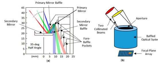
Figure 1.
(a) DEMETER WFOV telescope concept, and (b) a generic optical instrument accepting two collimated beams.
Consider the arbitrary optical instrument, shown in Figure 1b, which consists of an aperture, a baffled optical system, and a Focal-Plane Array (FPA). Not shown is the filter that establishes the instrument passband. Two collimated beams are incident to the aperture from directions and. Some of the energy carried by the beams is absorbed in the baffle and the rest is incident on the FPA, as indicated by the red and yellow spots on the FPA.
In the Monte Carlo Ray-Trace (MCRT) view of optics [3], a beam is considered to consist of a large number of randomly-spaced, parallel, equal-strength rays. We note that some of the rays making up the two collimated beams in Figure 1b are absorbed by a group of neighboring pixels within the FPA, and that the two spots in the FPA overlap; i.e., they share some of the same pixels. In general, a given pixelwill be illuminated by a whole continuum of beams whose directions are similar but differ within limited ranges ofand. Once again considering the MCRT vision of optics, some but not all of the rays from this continuum of beams are absorbed by pixel. Using a ray-trace we can compute the mean direction of all the rays absorbed by pixelas
whereis the total number of rays absorbed by pixel, and the sum is over the rays absorbed by pixel. In performing the ray-trace, spectral surface properties used are averaged over the wavelength interval of interest. The analysis described here is generally applicable to the visible, long-wave, and total bands, and so the wavelength symbol λ is suppressed. The power sensed by pixelis, whereis the power carried by each ray. The physical interpretation ofandis that the rays actually absorbed by pixel during the ray-trace can be replaced with rays all incident to the aperture from the same direction; while rays incident to the aperture from direction are by definition incident to the centroid of the corresponding optical point-spread function at the FPA, which does not necessarily lie on pixel.
Calibration of the instrument can be accomplished in one of two ways: (1) by having the real instrument regard a blackbody having a known temperature and recording the powerabsorbed by each pixel, or (2) by a corresponding MCRT simulation of the physical calibration. In both cases the radianceincident to the instrument aperture is independent of direction; i.e., it is a known constant. We then define a transfer function.
In a given wavelength interval the transfer function defined by Equation (2) is postulated to be an instrument constant, in which case the radiance corresponding to a measured pixel powerin that wavelength interval is
2. Monte Carlo Ray-Trace Simulation
During a Monte Carlo simulation, one hundred million rays are traced into the aperture of the DEMETER concept instrument of Figure 1a. Figure 2a shows the distribution of the rays on a 25-by-25-pixel FPA when the directional distribution of the rays arriving at the aperture corresponds to a blackbody calibration source, and Figure 2b shows the ray distribution on the FPA when one-half of the entrance aperture is occluded. If the transfer function defined by Equation (2) is truly an instrument constant, then the ray distributions in Figure 2a,b on the half of the FPA illuminated in both simulations should be identical. The degree to which this is not true is governed by (a) the inherent accuracy of the ray-trace and (b) scene dependence of the transfer function.
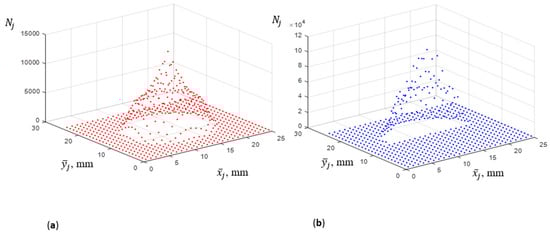
Figure 2.
(a) Ray distribution on the FPA when the instrument is regarding a blackbody and (b) ray distribution with one-half of the aperture occluded while regarding the same blackbody.
The inherent accuracy of the ray-trace method may be assessed by performing the simulated calibration using two different random number sequences and then observing the difference between the two resulting ray distributions on the FPA. This is illustrated in Figure 3a. The large differences near the edges are expected because the signal is very weak there. Differences on the interior, which are on the order of one to ten percent, are more representative. A few interior pixels exhibit unexpectedly larger differences. It is clear that a significantly larger number of rays will need to be traced in order to establish the accuracy of the proposed numerical focusing scheme.
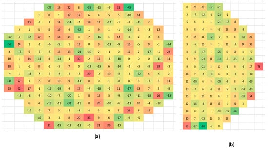
Figure 3.
(a) Percentage difference in the number of rays absorbed by each pixel when the instrument is regarding the same blackbody calibration source based on two different random number sequences, and (b) percentage difference in the number of rays absorbed by each pixel between the calibration case of Figure 2a and the test case of Figure 2b.
Figure 3b shows the percentage differences between the calibration case, corresponding to Figure 2a, and the test case, corresponding to Figure 2b. While pixel-to-pixel differences may be observed between Figure 3b and the right half of Figure 3a, the overall trends in the two figures are roughly the same. We interpret this to mean that much of the difference observed in Figure 3b can reasonably be attributed to the inherent limited accuracy of the MCRT simulation. The slightly higher differences in the left-most column of Figure 3b compared to those in the remaining interior columns may be attributed to an “edge effect” provoked by the lack of rays arriving from the occluded side of the entrance aperture. While real and of some concern, this edge effect is an artifact of the particularly stringent nature of the test in which the scene is abruptly occulted. It is noted that typical Earth scenes vary relatively slowly with direction, and so are not expected to suffer this edge effect.
3. Conclusions and Recommendations
We are encouraged to continue our pursuit of the simple but potentially effective scheme reported here for numerical unblurring of a focal-plane array image as an alternative to pursuing the design of a curved array. We conclude that further studies are needed in which a larger number of rays are traced and more realistic, slowly varying scenes are observed.
Funding
This effort was funded under an IRAD grant awarded on the basis of a NASA Langley FY2019 Joint Call for Early-Stage Innovative Ideas to address the Center’s Strategic Technology Investment Plan (STIP) Challenge No. 7, Earth and Space Science Measurements.
Conflicts of Interest
The authors declare no conflict of interest.
References
- Wielicki, B.A.; Barkstrom, B.R.; Harrison, E.F.; Lee III, R.B.; Smith, G.L.; Cooper, J.E. Clouds and the Earth’s Radiant Energy System (CERES): An Earth Observing System Experiment. B Am. Meteorol. Soc. 1996, 77, 853–868. [Google Scholar] [CrossRef]
- Priestley, K.J.; Ashraf, A.; Shankar, M.; Mahan, J.R. DEMonstrating the Emerging Technology for measuring the Earth’s Radiation. In Proceedings of the Paper 11151-23, Sensors, Systems, and Next-Generation Satellites XXIII, SPIE Remote Sensing, Strasbourg, France, 9–12 September 2019. [Google Scholar]
- Mahan, J.R. The Monte Carlo Ray-Trace Method in Radiation Heat Transfer and Applied Optics; Wiley-ASME Press: Hoboken, NJ, USA, 2019. [Google Scholar] [CrossRef]
Disclaimer/Publisher’s Note: The statements, opinions and data contained in all publications are solely those of the individual author(s) and contributor(s) and not of MDPI and/or the editor(s). MDPI and/or the editor(s) disclaim responsibility for any injury to people or property resulting from any ideas, methods, instructions or products referred to in the content. |
© 2019 by the authors. Licensee MDPI, Basel, Switzerland. This article is an open access article distributed under the terms and conditions of the Creative Commons Attribution (CC BY) license (https://creativecommons.org/licenses/by/4.0/).