1. Introduction
The building sector in Canada is one of the largest users of energy, consuming 32% [
1] of the total energy generated, and is consequently responsible for 30% [
1] of the total greenhouse gas (GHG) emissions. The impetus to reduce these emissions has led to the development of various clean technologies and processes. Wastewater heat recovery (WWHR) is one such clean technology, and due to the high density and flow rates of wastewater, it has the potential to satisfy a significant portion of building space heating and cooling demands, resulting in meaningful environmental and economic benefits.
The most ubiquitous type of WWHR systems are in-house drain heat recovery units used to preheat incoming domestic water. These units are typically small and are limited by low flow rates. However, the system proposed in this paper involves tapping directly into the sewer and thus has access to a constant supply of wastewater. There are currently 500 documented WWHR systems, of varying types, in operation around the world, most of them being located in Europe and Asia. These systems are able to provide between 10 kW and 20 MW of thermal power [
2].
According to [
3], the average temperature of domestic water going down the drain in a typical European household is 27 °C. Once this wastewater enters the sewer, it mixes with other wastewater streams and makes its way to a treatment facility. Typical wastewater temperatures range between 10 °C and 25 °C [
2]. On an average day, the city of Toronto consumes 949,000 m
3 [
4] of water. Cooling this volume of water by 2 °C would recover 8 million MJ of thermal energy that would otherwise be rejected to the environment. This waste heat is a potential source of thermal energy that is severely underdeveloped, especially in North America. The limit to the amount of energy that can be extracted from wastewater is imposed by the temperature sensitive biological treatment process [
5]. While the energy present in wastewater alone can provide meaningful reductions in building energy usage and greenhouse gas emissions, research indicates that using it as an energy source for heat pumps could be extremely promising.
The following example is a good indicator of the potential of wastewater as a source of thermal energy for heat pumps; According to [
6], wastewater temperatures in northern China range between 13.5 °C and 16.5 °C in the winter and 22 °C and 25 °C in the summer. This means that on average the wastewater temperature is approximately 20 °C higher than the ambient air temperature during the winter, and 10 °C lower than the ambient air temperature during the summer [
6]. Therefore, a wastewater sourced heat pump would operate with higher coefficient of performance (COP) than air source heat pumps and even ground source heat pumps. According to [
7], the heating COP of wastewater source heat pumps increases by 0.3 for every 2 °C increase in wastewater temperature. Alternatively, the wastewater can also be used as an energy sink to provide cooling.
Hospitals are excellent candidates for WWHR since they have large year-round heating and cooling loads, are large consumers of water [
5], and produce high temperature wastewater from cleaning, steam disinfection, cooking, and other demands. Due to this, hospitals have the highest energy intensity levels in Canada amongst all building types at 2.45 GJ/m
2 [
8], and with over 200 hospitals in Ontario [
9] this represents a significant energy demand that could be offset by WWHR.
Temperature data was obtained from Toronto Water for a major sewer near the hospital. The readings showed that the temperature varies between 17 °C and 19 °C with very little fluctuation. Flow data was also obtained for a major sewer line of comparable size to that of the one that runs near the hospital. The average hourly flow profiles were generated on a monthly basis and can be seen in
Figure 1.
2. System Configuration
The WWHR system consists of three major constituents; a wastewater collector, a heat exchanger, and a heat pump. One of the biggest impediments to WWHR is the issue of fouling. Passing unfiltered wastewater through heat exchangers results in a thin biofilm developing over the heat transfer area, thereby greatly diminishing the efficiency of the system over time. The function of the wastewater collector is twofold. In order to minimize fouling and prevent the system from being blocked, the collector contains a filter to remove large solids, such as plastic bags, that would otherwise completely clog the system, and fine particles that would diminish the effectiveness of the heat exchanger. Reference [
10] suggests using filters with a minimum diameter of 4 mm to prevent blockage inside the 20 mm diameter tubes which are typically used in wastewater heat exchangers. Once the wastewater has been screened, it is pumped up through a wet well to a heat exchanger where thermal energy is transferred between the wastewater and working fluid of the heat pump.
The heat exchanger acts as an intermediary between the raw sewage and the tube side fluid going to the heat pump. Although the sewage is screened before being pumped up to the heat exchanger, it still contains small impurities which would cause fouling over time, thereby greatly diminishing the performance of the system. In order to combat this, the heat exchanger used in this system has a dedicated cleaning system which periodically removes the biofilm from the surface of the tubes.
While the WWHR system can cover the entirety of a buildings thermal demand given sufficient flow, it is typically hybridized with conventional equipment—boilers and chillers—in order to limit capital investment. In many ways this overall system configuration is similar to geothermal systems, in that it has a high capital cost to install compared to conventional system and must be set up as a hybrid HVAC system in most cases in order to optimize between the initial capital and ongoing operational savings.
3. Methodology
A model was developed to evaluate the performance of the WWHR system compared to conventional HVAC equipment.
3.1. Existing System
Aggregated hourly heating and cooling loads were obtained for a large hospital in the greater Toronto area. The daily building loads for the hospital are shown in
Figure 2 and
Figure 3. The annual and peak thermal demands are shown in
Table 1.
For the existing plant, a boiler efficiency of 75%, a chiller COP of 4.0, and a cooling tower power draw of 0.0746 kW/ton were assumed for seasonal efficiencies for the analysis, which was based on typical performance.
3.2. Proposed System Parameters
The main energy drawing and transferring components of the proposed WWHR system are the heat exchanger, heat pump, and the auxiliary equipment.
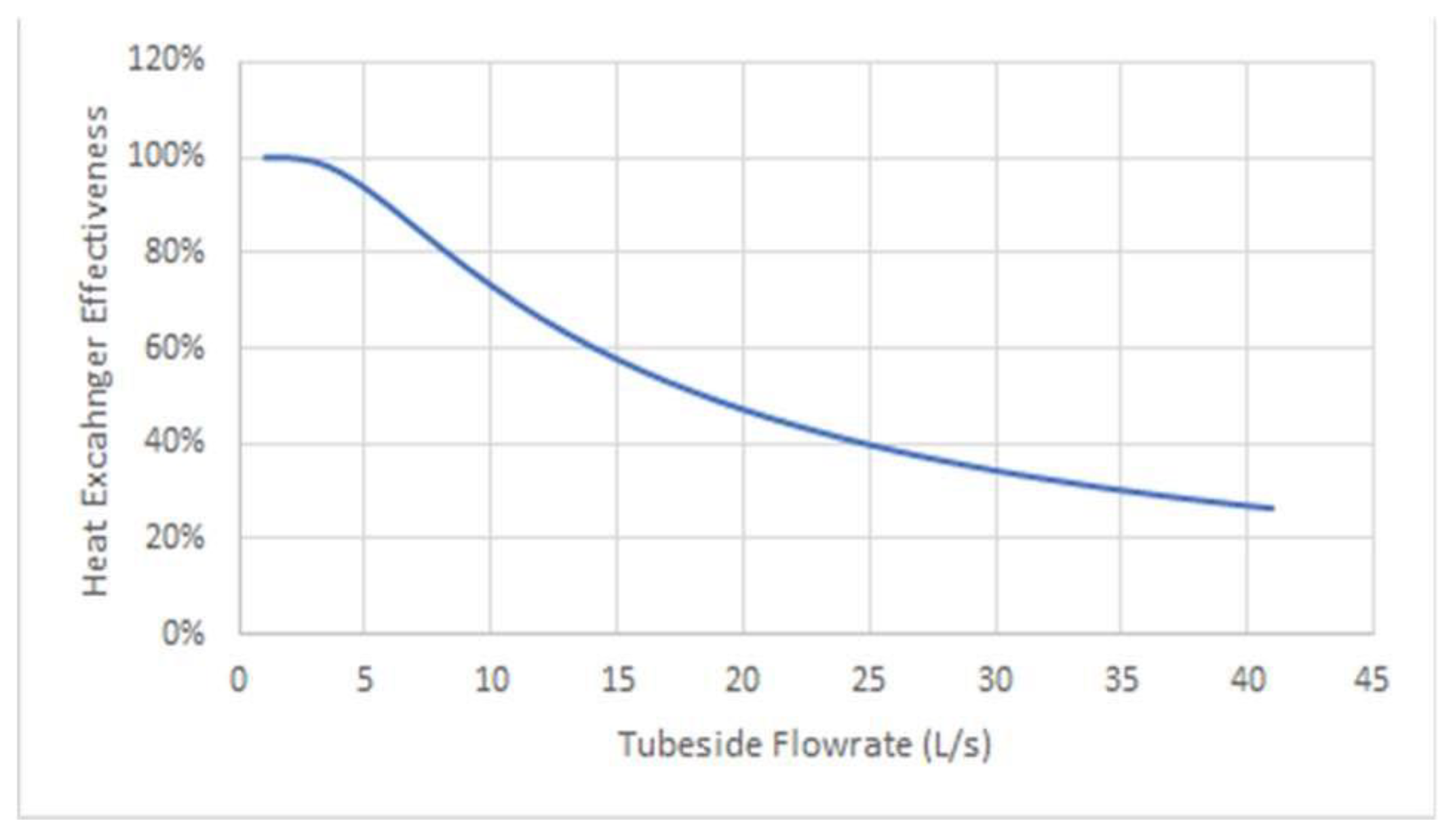
3.3. Heat Exchanger Parameters
The heat exchanger used in this system is a shell and tube type heat exchanger. As stated previously, the heat exchanger contains a dedicated cleaning system to ensure that the overall system is operating at peak performance at all times. For each heat exchanger, the flow rate of the wastewater going into the shell side is maintained at 32 L/s, whereas the flowrate of the tube side is allowed to vary depending on the building demand and temperature required by the heat pump to run at optimal COPs. The effectiveness curve of the heat exchanger as a function of varying tube side flow rates is shown in
Figure 4.
3.4. Heat Pump Parameters
For the analysis, heating and cooling supply temperatures of 60 °C and 5 °C were used. COP curves were obtained from a reputable manufacturer for both heating and cooling supply temperatures as functions of evaporator/condenser inlet temperatures. The heat pump COP curves can be seen in
Figure 5. Similar to the existing chiller, the heat pump parameters do not take into account part load capacities. The evaporator exit temperature during heating is held constant at 8.7 °C with a temperature difference across the condenser of 5.56 °C.
3.5. Auxiliary Electrical Consumption
The additional auxiliary equipment required for the operation of a WWHR system considered in the analysis are the controls, a wastewater (WW) supply pump, the cleaning system, and a mixer. A reputable heat pump manufacturer stated that the additional controls could be connected to the heat pump control panel with minimum additional electrical draw. Therefore, the controls are assumed to draw 140 W of energy per heat exchanger. The WW supply pump provides 32 L/s of flow to the heat exchanger as per manufacturer specification. To account for the depth of the sewer, the height of the heat exchanger inlet, and minor losses, a static head of 10 m with a pump efficiency of 80% was used. The power draw of the cleaning system was over-estimated to a nominal value of 1 kWh per day. A mixer will be used to create turbulence on the shell side of the heat exchanger, drawing an additional 1.26 kW.
3.6. Heat Transfer
The heat transferred across the heat exchanger is determined as
where
is the heat transferred across the heat exchanger in kW,
is the tube-side mass flow rate in kg/s,
is the specific heat of water in kJ/kg-K,
is the sewer temperature,
is the evaporator exit temperature, and
is the effectiveness of the heat exchanger. The temperature supplied to the heat pump is calculated as
where
is the temperature leaving the heat pump going to the heat exchanger.
3.7. Model Function
For the analysis, the WWHR was used to provide the base thermal demand, while conventional equipment served to provide the remainder. These calculations are carried out on an hourly basis, and energy consumption and associated costs are determined. The analysis is carried out for the hybridized WWHR system, as well as for conventional equipment.
4. Techno-Economic Analysis
The capital costs used in the financial analysis are shown in
Table 2, where the values were obtained from reputable companies.
The ideal/optimal design was iteratively determined to consist of 10 heat exchangers, as it provided the highest internal rate of return (IRR). This configuration can cover 33% of the total annual heating demand, and 33% of the total annual cooling demand, as is shown in
Figure 2 and
Figure 3. The WWHR system has peak heating and cooling capacities of 5140 kW and 3610 kW, respectively, and it is capable of covering 29% and 20% of their respective peak demands. The annual operating cost savings are
$404,853, with additional global adjustment savings of
$171,659. The capital cost of the WWHR system is
$6,499,000 and it would save
$576,512 annually, providing a simple payback of 11.27 years. For this 20 years project the IRR is 11.05%.
5. Conclusions
The viability of a WWHR system is dependent on the local energy prices, and an abundance of wastewater. A significant portion of the operational savings were derived from cooling because the WWHR system has a more favorable sink temperature than conventional chillers that rely on the outdoor ambient conditions, specifically during the summer. The proposed system is estimated to be typically 0.316 kW/ton lower than the conventional equipment operating in the hospital. The improved cooling efficiency would also lead to a decrease in electrical consumption which resulted in global adjustment savings of $171,659 based on Class A Ontario electricity rates. The cost of providing heating with this system is difficult using time-of-use rates or Class B rates since electricity is approximately 4 to 6 times more expensive than natural gas in Ontario. However, the hospital uses a Class A pricing structure, which is favorable for heating because the global adjustment only accounts for the peaks, which typically occur during the summer, rather than per volumetric consumption as is the case with time-of-use and Class B.
Based on these returns, the hospital would recoup its capital investment in just over 11 years, and would save
$576,512 annually. The WWHR system would be able to offset 5355 tones of CO
2 annually, with the vast majority coming from the displaced natural gas. The Ontario emissions factors used were 36 g of CO
2/kWh [
11], compared to 1.89 kg/m
3 of natural gas [
12].


