1. Introduction
In the study of the mechanical properties of materials, dynamic mechanical properties are becoming more and more important. Under dynamic conditions, it is difficult to measure pressure on solid surfaces directly. Thus, it is necessary to design a sensor that can be directly attached to the material surface. Polyvinylidene Fluoride (PVDF), as a new type of organic polymer material, has a strong piezoelectric effect after being polarized and can be fabricated into stress gauges, which have a high piezoelectric coefficient, wide frequency response, thin lateral dimension, no need of an external power supply, etc. Therefore, PVDF gauges are expected to play a special role in the direct measurement of dynamic loads. It is, therefore, necessary to understand its characteristics in a solid interface.
It is commonly agreed that the split Hopkinson pressure bar (SHPB) experiment is an effective method to test the dynamic mechanical properties of materials, and that the measurement technology is important. To accurately obtain the impact load of a specimen, the traditional method used is measuring the strain signal, which is pasted on the bars. This is an indirect method. However, there is still no effective method for measuring the loads directly on the surface of the specimen. At present, PVDF gauges have been used in dynamic experiments and some of them have been commercialized. Graham and Bauer [
1] studied the maximum pressure of the PVDF gauge in an air gun, and it was found that the test accuracy achieved 20 GPa and the maximum was 35 GPa. Bauer [
2] applied a PVDF gauge to the split Hopkinson pressure bar (SHPB) experiment, and found the measured value was larger than the theoretical value because of radial expansion after compression. Obara [
3] applied a self-made PVDF gauge to calibrate an impact experiment, and the highest pressure was 1 GPa. Xi [
4] calibrated a PVDF piezoelectric film (the stress range was 0~80 MPa) and obtained the relationship between the charge and the stress by SHPB experiments.Wu [
5] found that stress concentration appears if the area of the PVDF gauge’s sensitive part is less than the bar’s base on a SHPB device with bars of 37 mm in diameter. Furthermore, with a decrease of the sensitive part area, the stress concentration was more obvious. They obtained a dynamic piezoelectric coefficient,
k, that was equal to 29.05 pC/N, and pointed out that the value of
k changes with the production process and work conditions. Pang [
6] tested the sandwich type PVDF gauges on a SHPB device, and found that the sensitive area was a very important factor. With an increase of the sensitive area, measurement error decreased gradually, and the influence of the stress concentration also decreased. They calibrated the dynamic piezoelectric coefficient of PVDF gauges with a sensitivity area of 144 mm
2, and the
k was equal to 24.46 pC/N. Therefore, PVDF gauges have been proved to be used to directly measure the load in SHPB experiments. However, due to the need for the transformation of the stress and charge, the dynamic piezoelectric coefficients,
k, should be calibrated in advance and the work condition of
k must be the same as the condition of the calibration process.
In most references, the PVDF gauges and strain gauges were combined to measure the loads. Then, can PVDF gauges measure loads directly for some special conditions, especially if the strain gauges and other measurement methods are not able to calibrate the PVDF gauges? In this paper, the stress concentration problem with PVDF gauges were verified by SHPB experiments, and two methods to solve the problem were proved to be possible.
2. Experimental Methods
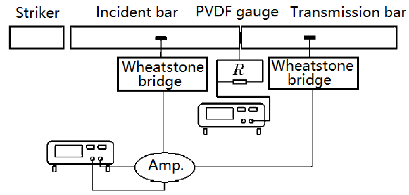
Figure 1 is a sketch of the SHPB experiment with PVDF gauges. The strain signal can be obtained by the strain gauges, which were pasted on the incident and transmission bars. The PVDF gauge is placed between the incident bar and the transmission bar. Under the impact pressure, the PVDF gauge will generate electric charges on both sides of the electrode. The voltage of the resistance that connects parallel to the PVDF gauge can be measured and the current flowing of the resistance can be obtained. Then, the charge amount can be obtained by integrating the current flowing. Finally, the load is calculated by the relationship between the charge and the load.
According to the one-dimensional stress wave theory, the elastic wave in a one-dimensional stress state is not distorted when propagating in the bars. Therefore, it can be considered that the SHPB system is one-dimensional. In the SHPB experiment, the strain gauges were pasted on the bars, and the strain signal was measured. Then, the contact load in the interface of the two bars was obtained. This is a mature method, and many experiments have proved the correctness and accuracy of this method. Therefore, it can be considered that the strain gauge method can obtain the "truth value" of the loads in the bars. Therefore, both strain gauges and the PVDF gauge were applied in the same experiments. If the two results are the same, it can be determined that the PVDF gauge is accurate and reliable. If not, it indicates some problems exist when PVDF gauges are used for measuring load in the solid interface. Then, it is expected to be corrected by some means.
3. Experiments with PVDF Gauges
The experiments were carried out on the SHPB device with aluminum bars with a diameter of 25 mm. Both bars were 1400 mm long and the striker was 500 mm long. Additionally, we also used electrical tape, which has a strong anti-pressure ability that is not easy to deform and has an extremely uniform thickness. Three kinds of tapes were used and the thickness was 0.02 mm, 0.056 mm, and 0.081 mm, respectively. Combining different thicknesses of tape can obtain more different thicknesses.
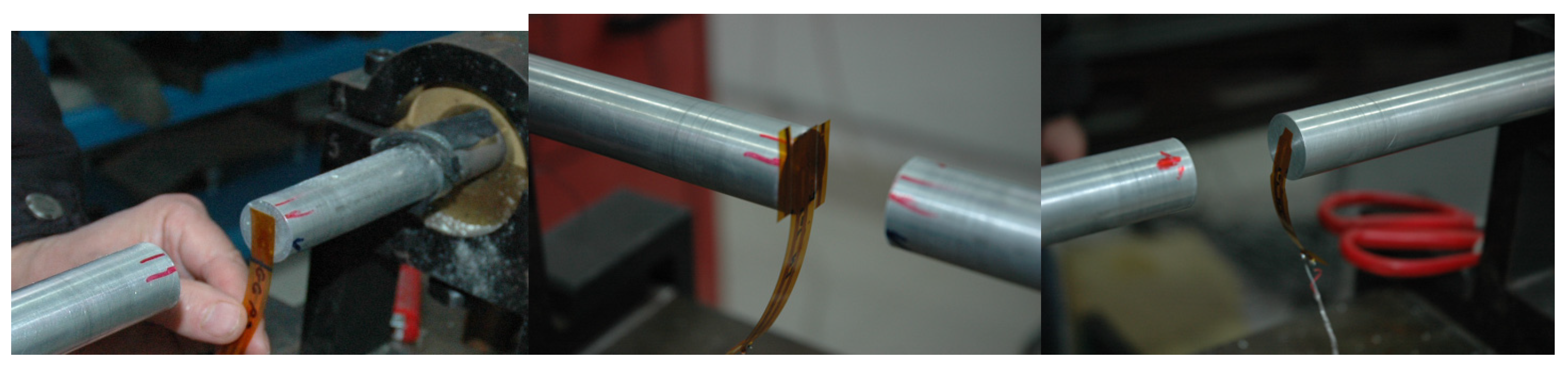
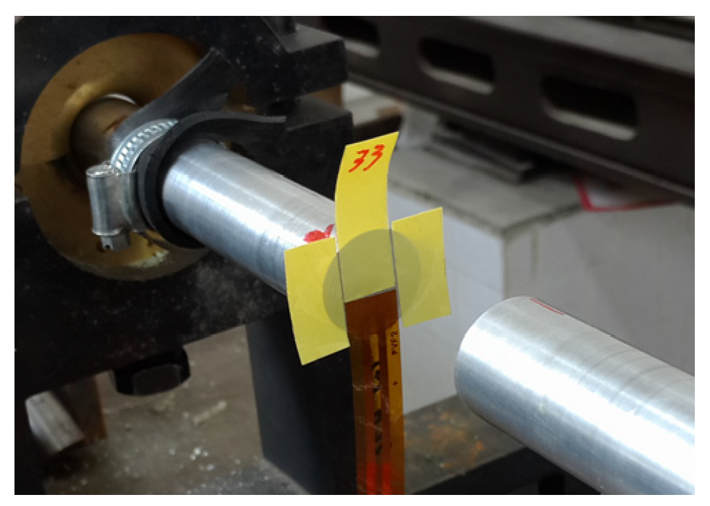
In experiment 1, the PVDF gauge was directly sandwiched between two bars. In experiment 2, the area around the PVDF gauge was filled with PVDF gauges. In experiment 3, the base around the sensitive area was removed, as shown in
Figure 2.
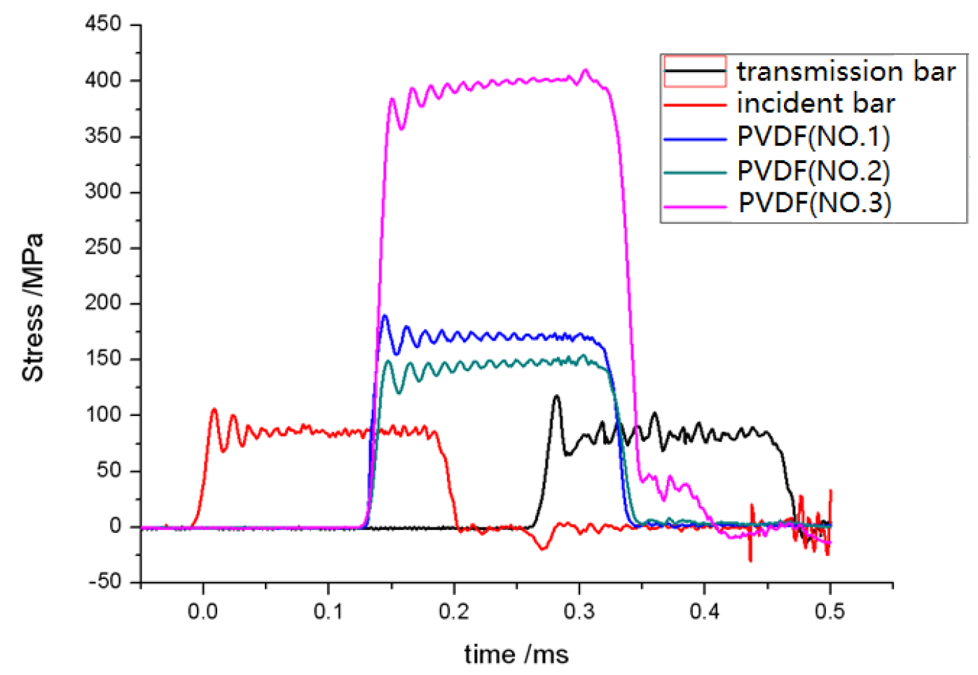
Figure 3 shows the experiment results. It can be found that the stress pulses in the incident bar and transmission bar obtained through the strain gauges are the same, and the average stress is about 84 MPa. This also indicates that the PVDF gauge does not change the stress waves in bars. In three experiments, the stress pulse width that was measured by the PVDF gauges were the same as that of the strain gauges, but the amplitude was different. The measured values of the three experiments were 172 MPa, 147 MPa, and 400 MPa, respectively. Compared with the stress in the bar, it is 2.0 times, 1.8 times, and 4.8 times, respectively.
Thus, the PVDF gauge sandwiched in the two solid interfaces generates higher pressures than the actual situation. The smaller the area of the sensitive area, the higher the pressures. This is precisely because the PVDF has a certain thickness, forming a physical bulge between the flat solid interface, which inevitably leads to the stress concentration.
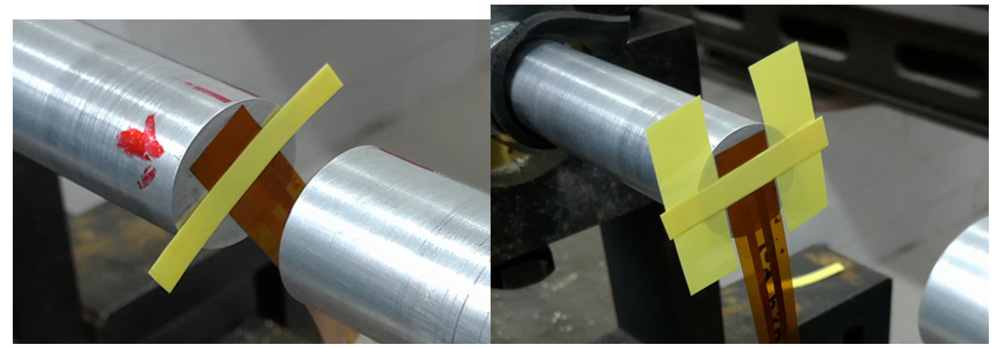
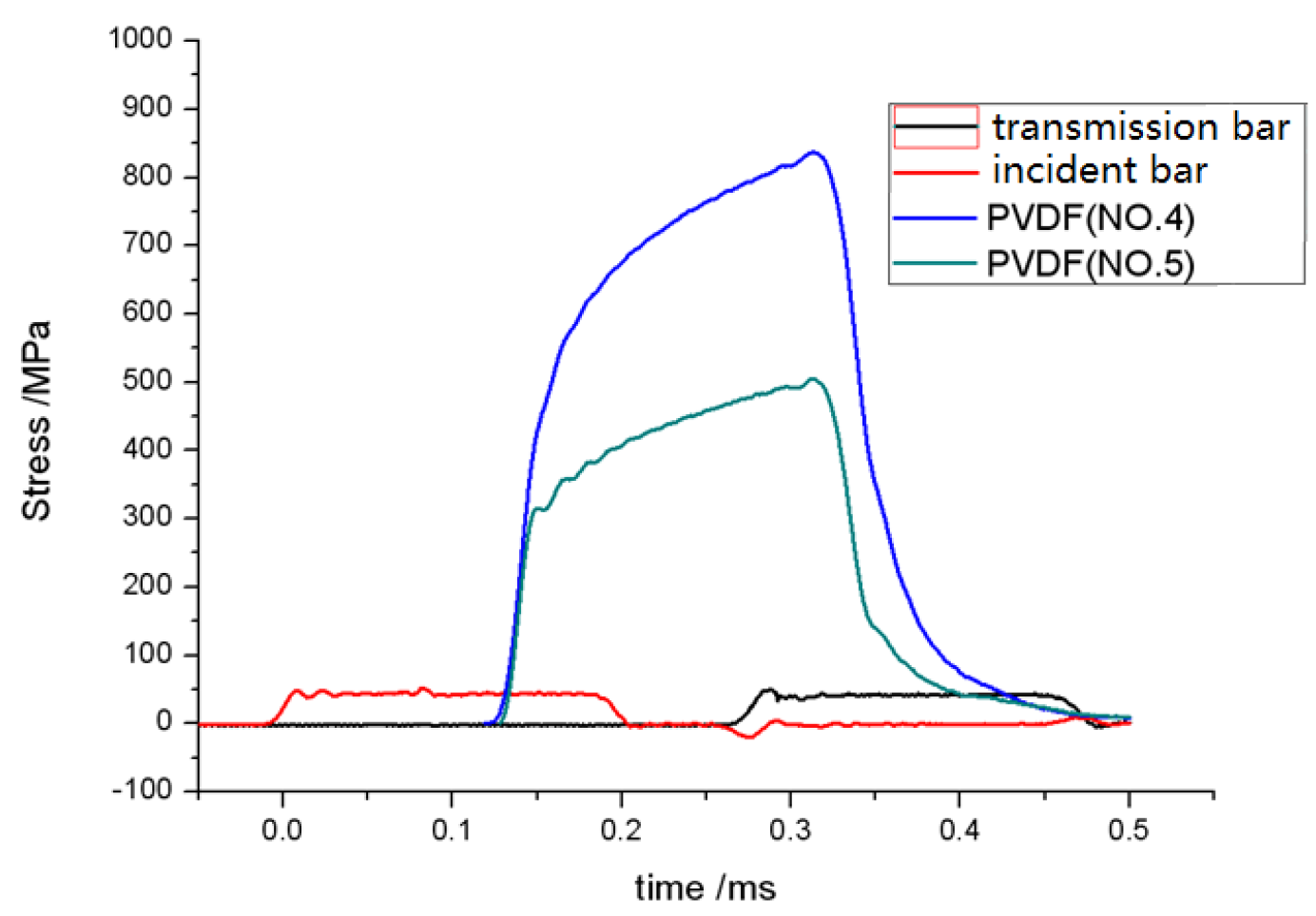
In experiment 4, the PVDF gauge was pasted with rectangular electrical tape with a thickness of 0.324 mm and a width of 6.0 mm. Experiment 5 was based on experiment 4, but both sides of the gauge were filled with electrical tape of a thickness of 0.081 mm, as shown in
Figure 4.
Figure 5 shows the experiment results. The stress signal in the incident bar and transmission bar was nearly the same at approximately 42 MPa. However, the shape of the signal measured by the PVDF gauges was different from that of strain gauges. The stresses measured by the PVDF gauges in both cases was 836 MPa and 501 MPa, about 20 times and 12 times of the stress in the bars, respectively.
The experiment results show that the stress concentration can be generated by placing PVDF gauges directly between the two solid interfaces. With the change in the hardness of the material, the PVDF test results were not identical and there was no obvious quantitative regularity. It shows that there are strict requirements when the PVDF gauges are used directly in the solid interface to measure the loads.
4. Methods to Eliminate Stress Concentration
The cause of the stress concentration is the physical bulge formed by the PVDF gauge, therefore, the primary way to eliminate this is to use something that fills the area around the PVDF gauge. The first method is adding a cushion and the second method is adding 502 glue (cyanoacrylate adhesive).
4.1. Adding Cushion
Electrical tape was used as a cushion, and placed around the PVDF gauge and then sandwiched them between the two bars, as shown in
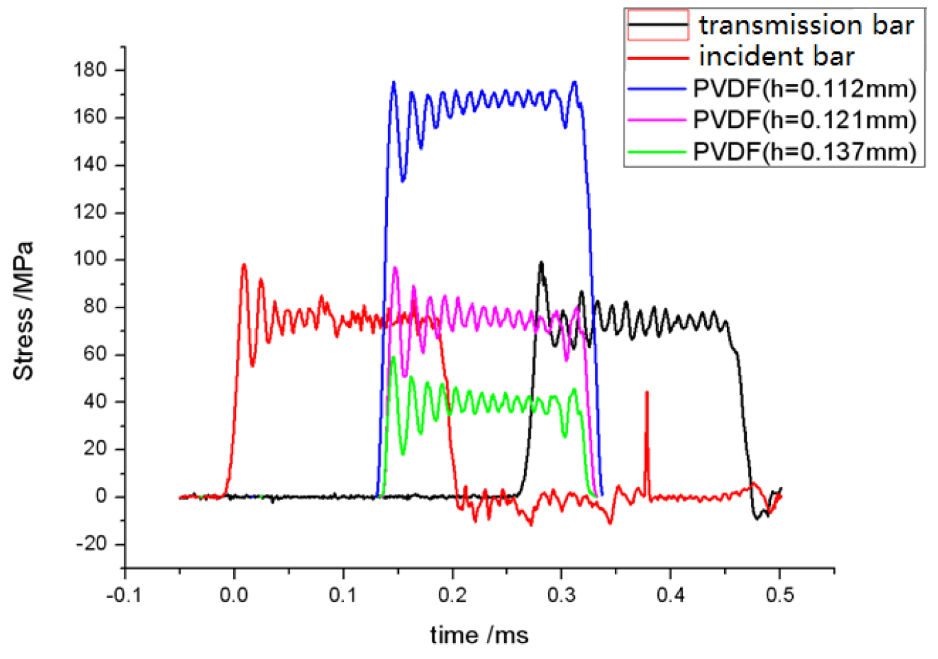
Figure 6. Depending on the pressure, different thicknesses of the cushion could be used.
Figure 7 shows the effects of different thicknesses of the cushion. It can be seen that the stress in the bars were 78 MPa. The stress pulse widths, measured by the PVDF gauge, were the same as that of the strain gauge, but the stress amplitudes were about 170 MPa, 78 MPa, and 40 MPa, respectively, when the thickness of cushion was 0.112 mm, 0.121 mm, and 0.137 mm. Evidently, the cushion thickness has an obvious influence on the measurement value of PVDF gauges. The thicker the cushion, the lower the measurement value. When the thickness of the cushion was 0.121 mm, the measurement value of the PVDF gauge was consistent with that of the strain gauge. In addition, it can be assumed that an increase in the thickness of the cushion results in a corresponding decrease in the measurement values, even as low as zero.
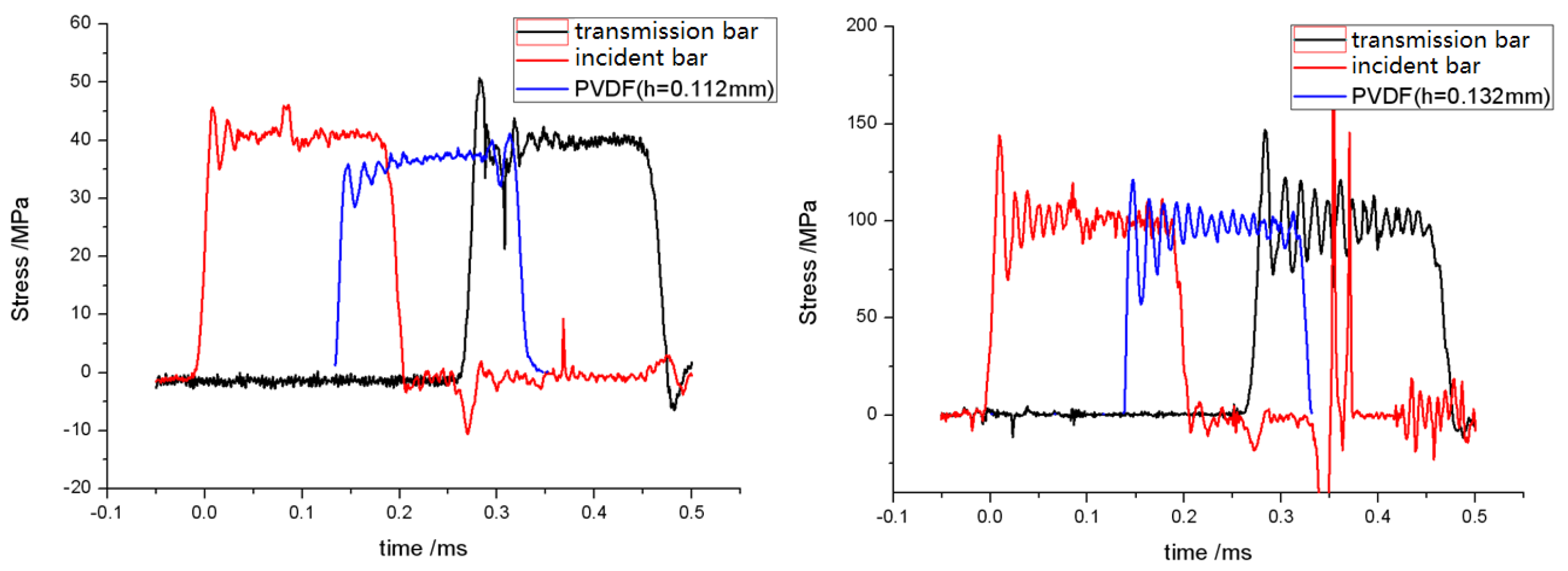
When the stress in the bar was 40 MPa, the PVDF gauge measurement value was 38 MPa, with the thickness of cushion at 0.112 mm. When the stress in the bar was 100 MPa, the PVDF measurement value was the same as the strain gauge when the thickness of the cushion was 0.132 mm, as shown in
Figure 8.
It can be seen that the method of adding a cushion can completely eliminate the stress concentration. However, the problem is that the cushion thickness cannot be selected in the case of unknown loads. This will make it difficult to use PVDF gauges directly. Therefore, if the load can be estimated in advance, the method can still be used to obtain the approximate load.
4.2. Using 502 Glue
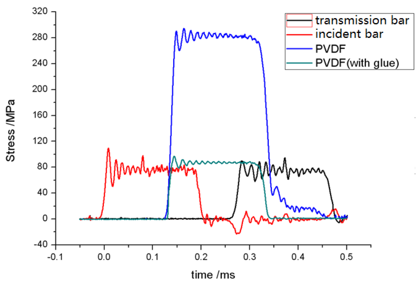
When placing PVDF gauges directly between the two bars, the stress on the bar was 79 MPa and the PVDF gauge measurement value was 285 MPa. In another situation, the PVDF gauge was placed in the center of the bar end and the 502 glue was evenly coated on the gauge and the whole bar end surface. Before subsequent measurement, the bars were fixed and glued. Now, the measurement value of the PVDF gauge is 85 MPa, which is similar to the stress in the bar, as shown in
Figure 9.
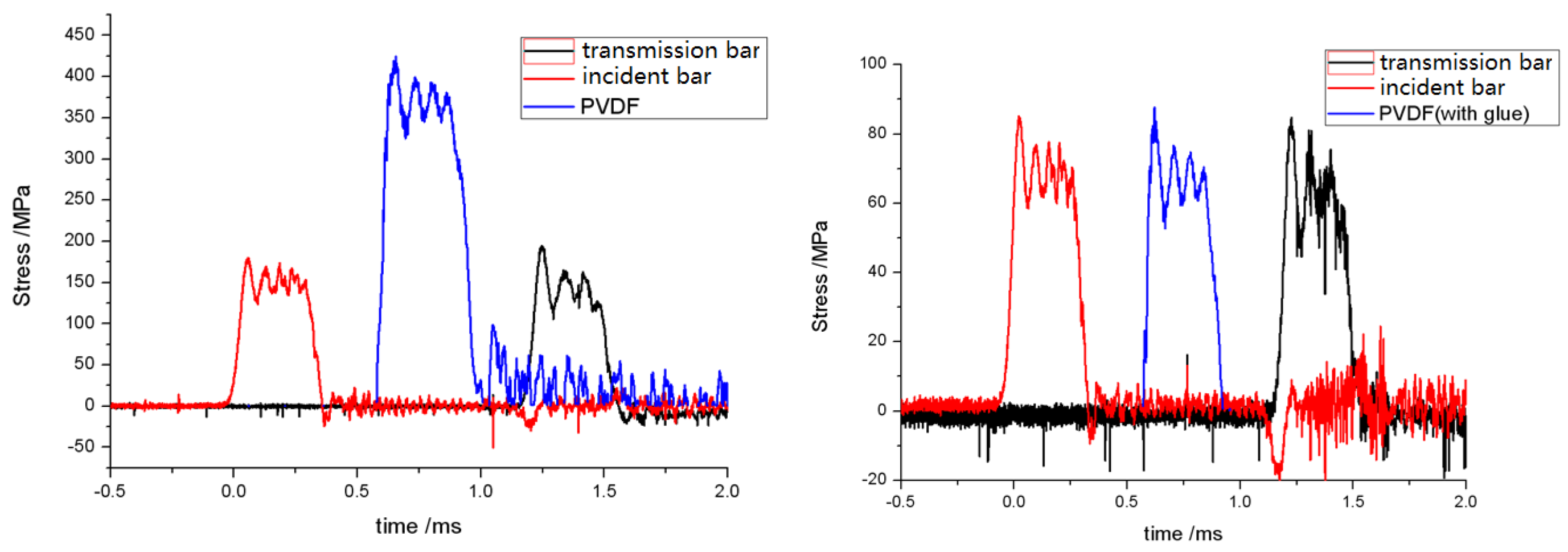
The same experiments were performed on the SHPB device with a diameter of 120 mm. When 502 glue was not used, the average stress on the bar was 145 MPa and the value test by the PVDF gauge was 375 MPa. Using 502 glue, the stress on the bar was 65 MPa, and the measured stress of the PVDF gauge was about 65 MPa, which was the same. The test results are shown in
Figure 10.
Thus, the stress concentration can be eliminated when the 502 glue is evenly coated on the gauge and the whole bar end surface. The reason is that 502 glue is equivalent to a cushion, and the load acts on the PVDF gauge and the cushion evenly. So the 502 glue effectively eliminates the interface physical bulge by the PVDF gauge, and the stress concentration is eliminated.
5. Conclusions and Discussions
In this paper, the SHPB experiments were carried out with the PVDF gauges sandwiched between two bars. The loads were measured by strain gauges and PVDF gauges. The experiment results were compared and analyzed. According to the analysis:
- (1)
There is a stress concentration when the PVDF gauge is sandwiched between the solid interfaces directly. The measured value is higher than in the actual situation. When the interface characteristics changed, the experiment results of the PVDF gauge are also changed. Therefore, if the PVDF gauges are used individually, the stress concentration must be eliminated;
- (2)
the method of adding cushioning can eliminate the stress concentration well, but it is difficult to determine the thickness of the cushion before the experiment. Therefore, if it is unavoidable to use a cushion, it is better to estimate the magnitude of the load in advance to determine the thickness of the cushion. In this case, the approximate value can be obtained by the PVDF gauge; and
- (3)
when using the PVDF gauge to directly measure the load in the solid interface, it is an optimal method to use 502 glue to eliminate the stress concentration.
In addition, the PVDF gauges must be kept even during the whole impact process. Any deformation of the PVDF gauges may generate abnormal experiment results.

