Abstract
We present the development of a contactless laser ultrasound system for nondestructive inspection of CFRP complex structures. Ultrasound are generated by a thermoelastic effect resulting from a green pulsed laser insulating a point of the inspected part. The resulting displacement of the surface point is probed by a two-wave mixing based interferometer working in the near infrared. The system is flexible and completely fiber-coupled. It is able to provide C-scans on complex shaped CFRP aeronautical structures.
1. Introduction
Laser ultrasonics [,] is an interesting technique for the inspection of composite structures with complex shapes. Ultrasonics is widely used in industry but requires either direct contact with the part inspected or to work at distance in water tank. For these reasons, optical contactless techniques are intensively studied, like active thermography [,], shearography [] or combination of both [,], Compared to classical UT, Laser UT (LUT) offers the advantage that no contact or couplant is needed and difficult to access points can be illuminated by laser beams at distance. LUT usually combines two principles: the first one is the generation of an ultrasound wave at distance by a laser [], the second is the detection of ultrasound at distance by an interferometric system. For the generation, a pulsed laser beam insulates briefly the material on its surface which generates the ultrasound through thermoelastic nondestructive effect. The second principle is the detection of ultrasound at distance by an interferometric system with a large optical etendue allowing working with potentially scattering surfaces [].
Our works aim at developing a robotized system addressing medium sized composite parts provided by aerospace industries. These parts have generally a square meter size and complex shapes []. Industrial companies which are part of this project produce curved or assembled parts fully made of carbon fiber reinforced polymers (CFRP). Economic interest of LUT has been demonstrated for high end military aircraft composite parts and the question obviously arises in the civilian industries. Application cases have to be distinguished into medium or large parts, respectively smaller or larger than the square meter []. Large parts could be scanned at high speed with high repetition rate laser (a few kHz), but this requires huge efforts in laser developments for both the generation and detection systems. On another hand, there is much interest for medium sized parts, with flexible and less expensive systems.
In this paper, we will present the development of our LUT system based on fibered generation and detection. We will compare different wavelengths of generation and present results on a curved CFRP structure.
2. Development of the Set-up
Since we want to combine the generation and detection laser beams, a common way is to use two separate wavelengths and to incorporate a dichroic beamsplitter which transmits one wavelength and reflects the other one. The detection systems available on the market work either in the near infrared (1.06 µm or 1.55 µm) or in the green (532 nm). We have chosen the PDL laser proposed by Tecnar Company with a detection probe based on two-wave mixing (TWM) in a GaAs photorefractive crystal []. This laser works at 1.06 µm and is based on an MOPA configuration. This system is already full fiber-coupled and is delivered with a 10 m robust flexible conduit which guides the different beams from remote sources and detectors on one side to a small lightweight optical probe on the other side. This system provides a high peak power of 500 W over pulse duration of 85 µs.
Concerning the generation, we needed to choose a cost-effective laser that is fiber-coupled and has a different wavelength than the detection. Literature shows that the efficiency of generating longitudinal waves in graphite/epoxy depends on the optical penetration depth, itself function of the wavelength []. Furthermore, short pulses (in the nanosecond or tens of nanosecond range) are required. TEA CO2 lasers (10.6 µm) are generally used in most LUT commercial systems because they industrialized and reliable [,]. However, there is no optical fiber technology for such pulsed CO2 lasers and light is brought to the inspected part via mirrors in an articulated arm, which does not offer the flexibility of optical fibers.
We have decided to work with generation at 532 nm. The advantage of this wavelength is that some companies offer fiber-coupled YAG Q-switched laser with sufficient energy to be used for generation (a few tens of mJ). The laser we considered is the Ultra 50 from Quantel which is initially coupled to a 3 m optical fiber interfaced through an SMA connector to the laser head. The laser works at 30 Hz repetition and allows 30 mJ at the output of the fiber. Because of this repetition rate, the repetition rate of the detection system was also set to 30 Hz.
Figure 1 shows an overview of the whole setup. The pulsed detection laser (PDL) unit incorporates the long pulse laser which is split in two beams by a beamsplitter (BS). One beam is sent into the pump beam fiber (PBF) and constitutes the pump beam for the photorefractive crystal (PRC) of the TWM detection unit. The second beam is directly sent to the optical head.
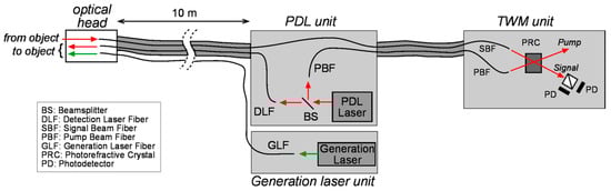
Figure 1.
Overall scheme of the system.
Figure 2 gives a detail sketch of the optical head which incorporates the detection optical probe provided by Tecnar. The latter contains the detection laser fiber (DLF) and the output beam is further collimated and passes through a frontal lens (FL) which focuses the illumination beam at a distance of 20 cm. The light reflected by the object enters the optical probe through FL and is injected into the signal beam fiber (SBF) which transports the signal beam directly to the TWM detection unit (Figure 1). In the TWM unit, the signal beam is mixed in the PRC with the pump beam. A differential photodetector (PD) module is placed in the signal beam after the PRC. The PDL laser allows long pulses of 80 µs duration with a repetition rate of 30 Hz and peak power of 300 W.
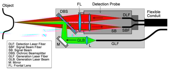
Figure 2.
Sketch of the laser ultrasound optical head.
The generation laser is an Ultra 50 from Quantel which delivers 30 mJ at the output of a 3 m fiber specially developed by Quantel. We used this generation laser fiber (GLF) to develop the optical head which is shown in Figure 2 and which combines the detection and generation beams. Later the 3 m fiber has been replaced by a new 10 m long fiber developed by Ceramoptec, with the same numerical aperture and core diameter as the former. This allows having the same length than the Tecnar flexible conduit and to attach the new GLF fiber to it and place the generation laser unit at the same remote location than the PDL unit. A computer controls the different units of the setup. The analog differential signal of the TWM unit is digitized by a high speed digitizer onboard a computer.
Figure 2 shows a detail of the optical head which combines the green generation laser beam (GLB) and the detection probe. A dichroic beamsplitter (DBS) transmits the illumination and signal beam (SB) to and from the probe to the object. The GLB is made incident to the same object point via a folding mirror M and the DBS which reflects the 532 nm wavelengths. The lens L position allows selecting the generation beam diameter. Although it is shown focused on the object, the GLB can be collimated or have different shapes.
3. Effect of Generation Laser Wavelength
It is well known that the wavelength of the generation laser is of primary importance for the efficiency of the generation process in graphite/epoxy laminates (CFRP). The latter is due to thermoelastic effect and its efficiency is driven by the optical absorption. Some wavelengths are weakly absorbed by the resin and totally absorbed by the carbon fibers. Conversely some other wavelengths are well absorbed by resin which acts as a bulk source. Therefore, the internal geometry of composite structures is of high importance for selecting the generation wavelength. Numerous studies have been performed in the past, comparing different available laser sources [,,,]. Mainly the CO2 laser line at 10.6 µm and fundamental YAG line at 1.06 µm were compared. It was found that the YAG line was more efficient for the generation, while the damage threshold for CFRP is smaller with YAG []. As already explained in the previous section, we have considered working at 532 nm for the generation for an easier separation with the detection beams through the optical head. From literature it is known that 532 nm has similar performances than 1.06 µm []. However, compared to previous literature, there was no comparative study on true CFRP samples of interest.
Compared inspections on a CFRP sample has been performed with our system and another one which uses the same detector (Tecnar TWM) but a TEA CO2 laser from Light Machinery for the generation. The sample is shown in Figure 3a, attached to a 6-axis robot arm for the scanning. The sample has dimensions of 185 × 145 × 4.4 mm3, with 6 flat bottom holes: 3 of them have 12 mm diameter and 1, 2 and 3 mm depths, the 3 others have 6 mm diameter and 1, 2 and 3 mm depths. These holes are arranged as shown in Figure 3b. Figure 3c show the temporal signals (A-scans) obtained on the sample with the two systems. In both cases, the first pulse is seen on the left. It arises from the displacement of the surface measured by the TWM detection after the generation laser pulse has reached the surface. Then echoes are observed and due to the ultrasound longitudinal wave travelling from the surface to the back wall of the plate and returning to the surface. It can be seen that, in the case of the YAG 532 nm generation, multiple echoes are observed while with the CO2 laser, only the first echo is visible. The multiple echoes with YAG come from the different travels of the same ultrasound longitudinal wave between the front surface and the back one. Observing multiple echoes is an advantage if one wishes to better analyze the attenuation of ultrasound signal for detecting tiny variations, e.g., related to porosity.
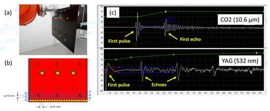
Figure 3.
(a) CFRP sample with 6 flat bottom holes, (b), sketch of the sample with scanning strategy, (c) A-scans obtained with both wavelengths.
The A-scans of Figure 3c are accumulated during scanning of the CFRP sample and provide the so-called C-scans after two distinct post-processing. The first one consists in measuring the change of signal amplitude between the first pulse and the first echo. The second one consists in measuring the time interval between them (Time-of-Flight, TOF). The first one allows detecting density variations, change of materials, porosity, whereas the second one allows measuring variations of defect depths. They are both of interest in nondestructive inspection. Figure 4 shows the amplitude and TOF C-scans obtained on the sample with both generation lasers. In the TOF, a given color is associated with the time interval between the first pulse and the echo. The yellow color corresponds to the back wall echo. The scanning step is 1 mm. It can be seen that contrast in attenuation is better with YAG, while they are roughly equivalent with TOF.
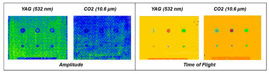
Figure 4.
C-scans obtained in Amplitude and Time-of-Flight with two different generation wavelengths.
It can be seen on these results that the amplitude variations are better contrasted in the case with the YAG laser generation than with the CO2. Concerning the TOF, contrast is equivalent between both systems for the deeper defects (in the middle and on the right). Shallow defects (1 mm depth) are barely visible in both cases but at such depths, it is usually difficult to distinguish between both first pulse and first echo, which is a specificity of pulse-echo methods (“dead zone”).
Other parameters of interest like the geometry of generation beam, and distance and angle with respect to the sample, have been discussed earlier in details in [].
Currently we are working with an optical parametric oscillator (OPO) laser emitting between 3 and 4 µm wavelength. Such wavelength should give better performances than other wavelengths []. In the past, such lasers were difficult to find with fiber coupling, which is no longer the case.
4. Inspection of Complex Shaped CFRP Structure
The fully fiber-coupled LUT system developed with a collimated 532 nm pulsed laser for generation and TWM detection at 1064 nm has been used in various inspections. A good example is shown in Figure 5. A portion of slat is shown at Figure 5a. It is a made with monolithic CFRP skins, arranged in a curved shape, with a stiffener with a T profile in the inner part of the structure. Artificial defect zones have been created between the skin and the stiffener. They are marked on the surface by white lines. Figure 5b shows the LUT system in position in front of the sample. The scan has been performed with a sampling distance of 2 mm in every direction, keeping the angle normal to the surface and the distance fixed from the surface (a few cm).
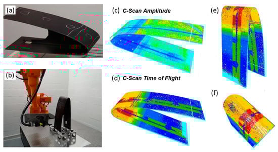
Figure 5.
Inspection of complex shaped composite structure. (a) Specimen, (b) During the scan, (c,d) C-scan, resp. in amplitude and time-of-flight, (e,f) different perspective angles of the time-of-flight C-Scan.
After compilation of A-scans in all points, a post-processing allows forming C-scans, both in amplitude (Figure 5c) and time-of-flight (Figure 5d). The TOF displays in false color the time interval between the first pulse and the first echo, coming back from the back wall of the skins (dark blue), the back wall of the upper part of the T profile of the stiffener (medium green). One can see a change of color in the skin signal, turning from dark blue to yellow. This is due to the higher thickness in the most curved part of the sample. Also the signal from the interface with the T profile turns from green to red. The different circular defects (debonding between the skin and the stiffener) are easily seen as different color patches in the stiffener signal. Rotation of the 3D C-scans allows best viewing the different defects (Figure 5e–f).
5. Discussion—Conclusions
We have shown the development of a laser ultrasonic system for nondestructive inspection of complex shaped CFRP structures. The system combines two segments. The first one is an interferometer for the detection of ultrasound at distance with a fiber-coupled system based on the two-wave mixing in photorefractive crystals at 1064 nm, in combination with a long pulse (85 µs) YAG laser. The second one is a YAG Q-switch nanosecond pulsed laser working in the green and which has been coupled to a robust optical fiber. We have developed an optical head which allows coupling both beams. This system is attached to a robot arm which allows scanning curved shaped structures.
Author Contributions
J.-F.V. developed the system, with help of C.T., F.L. and M.G. M.G. wrote the paper.
Acknowledgments
These results have been obtained with financial support of Wallonia under the project TECCOMA (contract No 7281) in the frame of SKYWIN competitiveness pole. The authors would like to thank Julien Walter, Louis-Daniel Théroux and Tomy Brouillette from CTA, St Hubert, QC, Canada, for providing access to their LUT system with CO2 generation laser. The authors would like also thank industrial partners of TECCOMA project for providing access to samples.
Conflicts of Interest
The author declares no conflict of interest.
References
- Scruby, C.B.; Drain, L.E. Laser Ultrasonics. Techniques and Applications; Adam Hilger: Bristol, UK; New York, NY, USA; Philadelphia, PA, USA, 1990. [Google Scholar]
- Monchalin, J.-P. Laser-ultrasonics: From the laboratory to industry. AIP Conf. Proc. 2004, 700, 3–31. [Google Scholar]
- Maldague, X. Theory and Practice of Infrared Technology for Nondestructive Testing; John Wiley & Sons: New York, NY, USA, 2001. [Google Scholar]
- Jorge, I.; Venegas, P.; Vega, L.; Lopez, I.; Vollheim, B.; Krausz, L.; Georges, M. Review of thermal imaging systems in composite defect detection. Infrared Phys. Technol. 2013, 61, 167–175. [Google Scholar] [CrossRef]
- Kalms, M.; Osten, W. Mobile shearography system for the inspection of aircraft and automotive components. Opt. Eng. 2003, 42, 1188–1196. [Google Scholar]
- Georges, M.P. Comparison between thermographic and holographic techniques for nondestructive testing of composites: Similarities, differences and potential cross-fertilization. In Proceedings SPIE 9660 of SPECKLE 2015: VI International Conference on Speckle Metrology, Guanajuato, Mexico, August 2015; SPIE: Bellingham, WA, USA, 2015; Volume 9660. [Google Scholar]
- Georges, M.P. Speckle interferometry in the long-wave infrared for combining holography and thermography in a single sensor. Applications to nondestructive testing: The FANTOM Project. In Proceedings SPIE 9525 of Conference Optical Measurement Systems for Industrial Inspection IX, Munich, Germany, June 2015; SPIE: Bellingham, WA, USA, 2015; Volume 952557. [Google Scholar]
- Kalms, M.; Focke, O.; von Kopylow, C. Applications of Laser Ultrasound NDT method on Composite structures in Aerospace Industry. In Proceedings SPIE 7155 of Ninth International Symposium on Laser Metrology, Singapore, October 2008; SPIE: Bellingham, USA, WA, USA, 2008; Volume 71880E. [Google Scholar]
- Voillaume, H.; Simonet, D.; Brousset, C.; Barbeau, P.; Arnaud, J.-L.; Dubois, M.; Drake, T.; Osterkamp, M. Analysis of Commercial Aeronautics Applications of Laser Ultrasonics for Composite Manufacturing. Proceeding of 9th European Conference on Non Destructive Testing (ECNDT2006), We.1.1.1 (2006). Available online: http://www.ndt.net/article/ecndt2006/doc/We.1.1.1.pdf (accessed on 28 June 2018).
- Blouin, A.; Monchalin, J.-P. Detection of ultrasonic motion of a scattering surface by two-wave mixing in a photorefractive GaAs crystal. Appl. Phys. Lett. 1994, 65, 932–934. [Google Scholar] [CrossRef]
- Stratoudaki, T.; Edwards, C.; Dixon, S.; Palmer, S. The role of epoxy resin in the mechanism of laser generated ultrasound in carbon fiber reinforced composites. In Proceedings SPIE 5046 on Conference Nondestructive Evaluation and Health Monitoring of Aerospace Materials and Composites II, San Diego, USA, August 2003; SPIE: Bellingham, WA, USA, 2003; pp. 89–98. [Google Scholar]
- Lorraine, P.; Dubois, M.; Bauco, A.S.; Filkins, R. A new laser source for ultrasound generation in composites. AIP Conf. Proc. 2000, 509, 295–301. [Google Scholar]
- Dubois, M.; Lorraine, P.; Venchiarutti, B.; Bauco, A.S.; Filkins, R.; Drake, T.; Yawn, K. Optimization of temporal profile and optical penetration depth for laser-generation of ultrasound in polymer-matrix composites. AIP Conf. Proc. 2000, 509, 287–294. [Google Scholar]
- Dubois, M.; Chuang, S.-Y.; Lorraine, P.; Drake, T.; Yawn, K.; Filkins, R. Progress on the development of an advanced laser ultrasound generation source for inspection polymer-matrix composites. AIP Conf. Proc. 2002, 615, 300–307. [Google Scholar]
- Vandenrijt, J.F.; Languy, F.; Thizy, C.; Georges, M.P. Nondestructive inspection of aerospace composites by a fiber-coupled laser ultrasonics system. In Proceedings SPIE 1044 of Fifth International Conference on Optical and Photonics Engineering, Singapore, June 2017; SPIE: Bellingham, WA, USA, 2017; Volume 104491K. [Google Scholar]
Publisher’s Note: MDPI stays neutral with regard to jurisdictional claims in published maps and institutional affiliations. |
© 2018 by the authors. Licensee MDPI, Basel, Switzerland. This article is an open access article distributed under the terms and conditions of the Creative Commons Attribution (CC BY) license (https://creativecommons.org/licenses/by/4.0/).