1. Introduction
Typical accidents in thermal power plants occur primarily due to creep damage. Thus, predicting the creep life is very important to maintain safe operation of thermal power plants for a long-term period. A destructive testing technique can predict accurately the creep life compared to other techniques. However, the associated technique has some problems: the specimen must be extracted from an actual plant, etc.
We conducted a high-temperature indentation test to estimate a creep constitutive equation, known as Norton’s law [
1,
2]. The high-temperature indentation test can be placed as intermediate one between destructive and nondestructive tests. The Norton’s law relates between the creep strain rate
and stress σ as follows.
where
k and
n denote the creep coefficient and creep exponent, respectively. The creep coefficient and creep exponent can be accurately identified from the relationship between the time and the impression size.
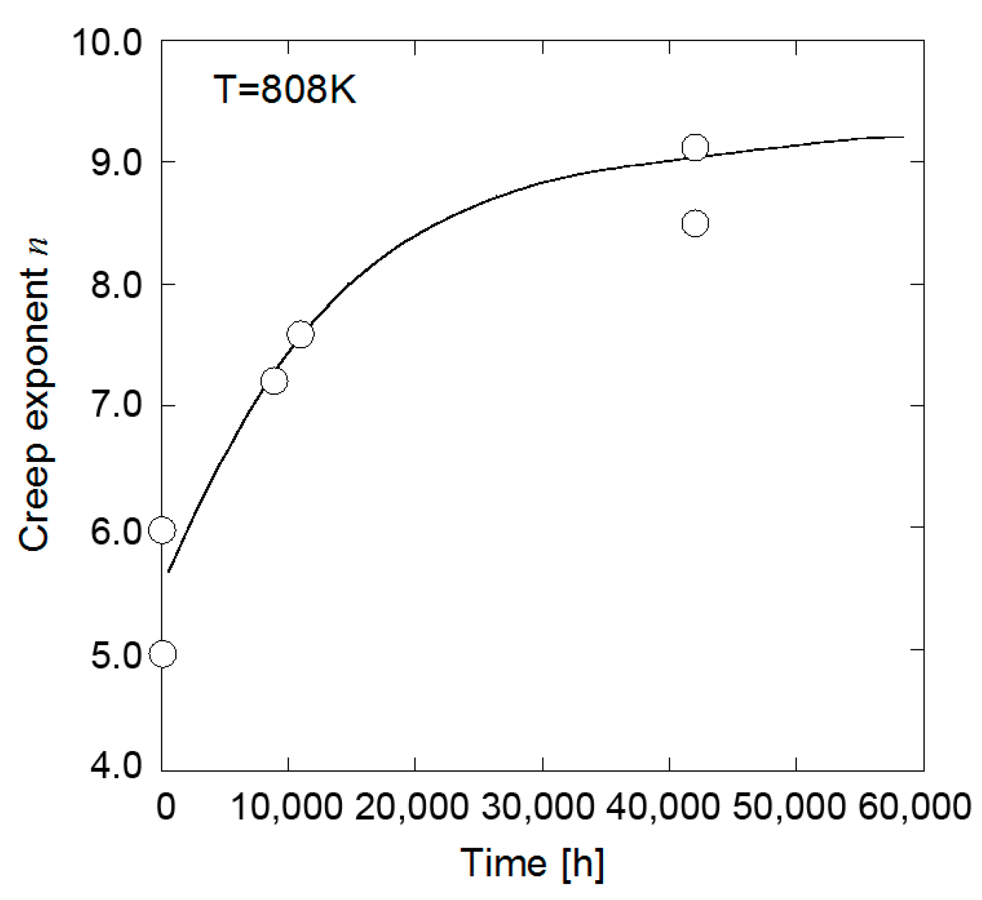
Walser et al. conducted uniaxial creep tests for unused and wasted boiler tubes and investigated the relationship between the creep exponent and operating time [
3]. As shown in
Figure 1, the result showed that the creep exponent increases monotonically with the increase in the operating time. Consequently, they stated that the creep exponent has capability to predict the creep life. It is, however, difficult to apply their method to an actual component because several large specimens must be cut off from the component. In contrast, the creep exponent and creep coefficient can be determined via the high-temperature indentation creep test only once. Therefore, the high-temperature indentation creep test is expected to be a practical technique for the creep life prediction.
In this study, a uniaxial creep test was conducted to prepare specimens with different creep damage ratios. Subsequently, the high-temperature indentation creep test was conducted to determine the creep exponent and creep coefficient for each specimen. From those results, we proposed a creep life prediction method based on the relationship between the creep exponent and creep coefficient.
2. Estimation of Creep Constitutive Equation by High-Temperature Indentation Creep Test
2.1. High-Temperature Indentation Creep Test
In the high-temperature indentation creep test, the relationship between the impression size and the testing time is obtained by indenting a specimen with a spherical ball under a high-temperature environment. The creep exponent and creep coefficient in the Norton’s law can be estimated from the relationship. The estimation method is as follows.
When semi-infinite creep media were indented with a spherical ball, the relationship between the spreading ratio of the impression radius and indentation load can be given as follows.
where
represents the non-dimensional impression radius ratio,
and
R and
P denote the radius of indentation ball and indentation load, respectively. Then,
η is the correction coefficient given as follows.
where
r is the radius of the specimen. The procedure to evaluate the creep constitutive equation is shown in
Figure 2. In performing the high-temperature indentation creep test, the impression radius
a needs to be measured at several intervals of time
t under a constant loading condition
P, wherein a logarithm of the non-dimensional impression ratio
is plotted as a function of the logarithm of the mean contact pressure
. The creep exponent and coefficient can be identified from the gradient and vertical axis intercept on the graph.
2.2. Specimen Preparation and Test Procedure
In order to prepare the specimens with different creep damage ratio for the high-temperature indentation creep test, a uniaxial creep test was conducted. ASME Grade 122 steel, which is candidate material of advanced-ultra super critical thermal power plants, was employed for the uniaxial creep test. The shape of the specimen is a parallel part size of φ 4 × 5 mm which is nonstandard shape. An original uniaxial-creep testing system based on the lever rule with a leverage ratio of 1:10 was used for the small specimen. The uniaxial creep test was performed under two testing conditions; one is 923 K and 120.4 MPa, the other is 973 K and 70.8 MPa. The displacement of the specimen was measured using a dial gauge set at the lever. Under these testing conditions, a creep rupture test was conducted to identify the rupture time. Subsequently, three specimens with different creep damage ratios Φ = 0.25, 0.50, and 0.75 were prepared based on this rupture time.
Figure 3 shows the experimental procedure to conduct the high-temperature indentation test for the interrupted specimen. The cylindrical specimen was cut off at the parallel part of the specimen as shown in
Figure 3. The cut surface was polished using a buff with a diamond suspension. The high-temperature indentation test was conducted for the polished surface using an original high-temperature indentation testing machine with a leverage ratio of 1:3, as shown in
Figure 3. An alumina ball with a diameter of 4 mm was employed as the indenter. The testing temperatures corresponded to those in the uniaxial creep test. The indentation load was fixed at 331.4 N. The indentation test was interrupted every 100 h to record variation of the impression radius with time. The impression radius
a was measured using a digital microscope (TMR-1, YASHIMA OPTICAL CO., LTD., Tokyo). The indentation test was performed for approximately 500 h.
2.3. Creep Exponent and Creep Coefficient
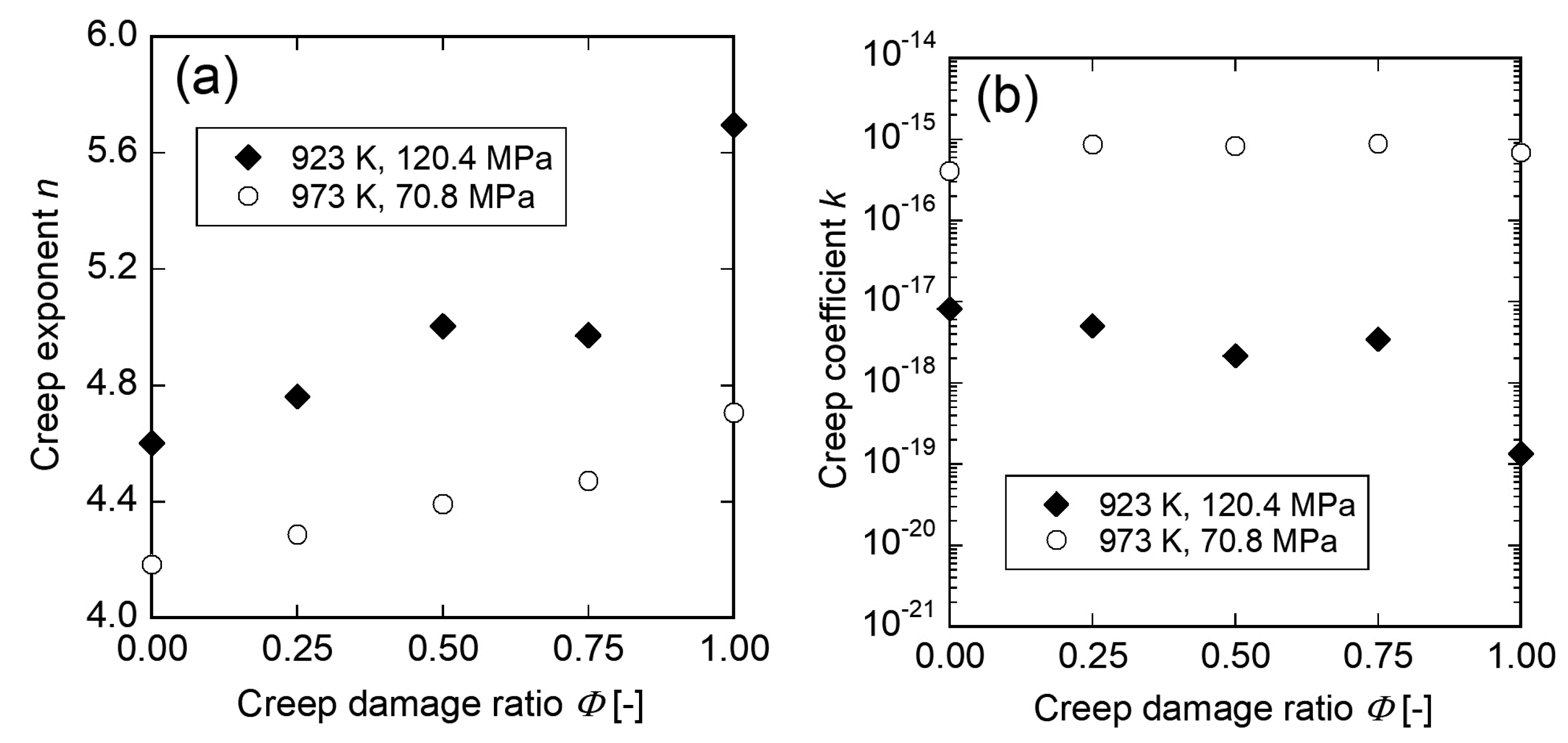
Figure 4 shows the creep exponent and creep coefficient evaluated by the high-temperature creep indentation test as a function of creep damage ratio. In
Figure 4a, the creep exponent linearly increases as the creep damage ratio increases in each specimen. Further, the specimen damaged under the condition of 923 K and 120.4 MPa has larger creep exponent than the specimen damaged under the condition of 973 K and 70.8 MPa. In contrast, the creep coefficient slightly decreases as the creep damage ratio increases. In addition, the specimen damaged under the condition of 923 K and 120.4 MPa has smaller creep coefficient than the specimen damaged under the condition of 973 K and 70.8 MPa. These results imply that the creep life can be predicted by using the creep exponent and creep coefficient.
3. Proposal of New Creep Life Prediction Method Based on Creep Exponent and Creep Coefficient
3.1. Conventional Method Based on Vickers Hardness
As an instance of conventional creep life prediction methods, Vickers hardness method was applied to the specimens prepared in
Section 2.2. The relationship between the hardness difference and creep damage ratio is shown in
Figure 5. The Vickers hardness difference represents the difference between the Vickers hardnesses of the grip part (HV
0) and testing area (HV) in the interrupted specimen. The Vickers hardness difference monotonically increases as the creep damage ratio increases. However, the Vickers hardness difference varies strongly depending on the temperature and stress levels which the specimens have experienced, even though the specimens have same creep damage ratio each other. Therefore, in order to apply the Vickers hardness method to actual components, we have to preliminarily obtain the relationship between the hardness difference and creep damage ratio in various temperature and stress conditions.
3.2. Proposal of New Parameter for Creep Life Prediction
As shown in
Figure 4a, the creep exponent and creep coefficient also varied depending on the temperature and stress levels which the specimen has experienced. In order to develop a more practical creep life prediction method based on the creep exponent and creep coefficient, we proposed a new parameter which is uniquely determined by the creep damage ratio regardless of the temperature and stress conditions.
F.K.G. Odqvist and J. Hult have reported that a logarithm of the creep coefficient can be linearly plotted as a function of the creep exponent in typical heat resistant steels [
4]. The relationship between the creep exponent and a logarithm of the creep coefficient in other materials including non-ferrous metals and ceramics has been investigated by T. Mita et al. [
5]. As the result, the linear relationship was also observed in the materials, in addition, the gradient and vertical axis intercept on the graph depended on the material. According to these researches, the relationship between the creep exponent and creep coefficient can be expressed as,
where
A and
B are constants depending on material. We focused on the relationship expressed as Equation (6) to develop a new parameter for creep life prediction.
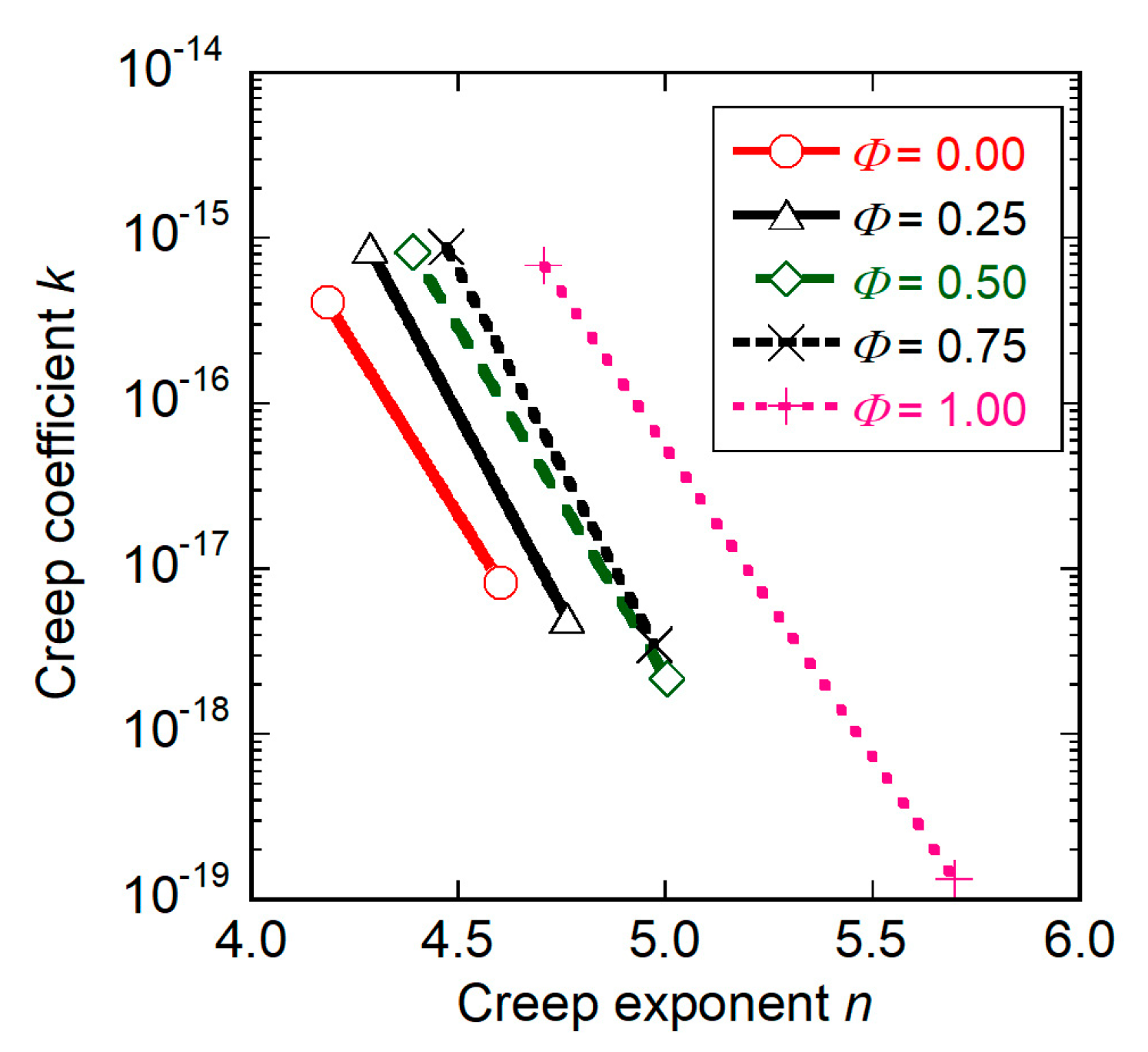
The relationship between the creep exponent and a logarithm of creep coefficient obtained through the high-temperature indentation creep test is plotted in
Figure 6. In the graph, the approximate lines are drawn for each creep damage ratio. It is confirmed that the gradient
A of approximate lines is almost constant with creep damage ratio, in contrast, the intercepts
B of approximate lines are changed with creep damage ratio. Equation (6) is rewritten as,
If the
A is constant, the logarithm of
B can be determined by the creep exponent and creep coefficient obtained through the high-temperature indentation creep test. The gradient of approximate line for the unused specimen (
Φ = 0.0) shown in
Figure 6 was employed as the constant
A.
The logarithm of
B normalized by the logarithm of
B0, which is denoted by
, is plotted as a function of the creep damage ratio in
Figure 7. The logarithm of
B0 is obtained from the unused specimen using Equation (7). In
Figure 7, the
linearly increases as the creep damage ratio increases. Furthermore, the
is not affected by the temperature and stress conditions. The approximate line is expressed as,
where
and
for our material. The correlation coefficient
ρ was evaluated to be 0.959. Equation (8) indicates that the
is uniquely determined by the creep damage ratio. Consequently, the creep life of material can be predicted with a high accuracy using the
parameter.
4. Conclusions
In this study, the creep exponent n and creep coefficient k on specimens with different creep damage ratios were evaluated via the high temperature indentation creep test. As the result, a creep life prediction method was proposed based on the new parameter , which is uniquely determined by the creep damage ratio regardless of the temperature and stress conditions.

