Abstract
The subsurface nature of Crack Tip Opening Displacement (CTOD) makes its direct measurement very difficult, if not impossible. During fracture toughness testing, CTOD is commonly calculated by applying a plastic hinge model using externally applied clip gauges. However, clip gauge CTOD calculations merely provide information relating to the center of the defect (which is typically the most critical point, but not always). For the case of a finite-length surface defect, CTOD will be variable over the defect front. Exact knowledge of CTOD over the entire front is useful for detailed calculations, such as crack profile evolution due to ductile tearing or calculations involving interacting defects. To experimentally measure the CTOD at locations other than the center of the crack, the authors propose a technique based on full field three-dimensional profile measurement of the notched surface by means of stereoscopic Digital Image Correlation (3D-DIC). The method is based on the plastic hinge model assuming that the crack flanks rotate in a rigid manner around a plastic hinge point in the un-cracked ligament. Having measured full-field out-of-plane displacement at the surface of the specimen around the crack using the 3D-DIC method, CTOD can be inferred over the entire crack front. Results show that, due to the acceptable agreement between the DIC based calculation and CTOD measured from cast replicas, the proposed technique has a sufficient accuracy to measure CTOD on the entire crack front in plastically deforming specimens.
1. Introduction
Determining criteria for the failure due to pre-existing structural defects is a fundamental driver for structural integrity analysis. Accurate experimental measurement of fracture toughness is required for the application of fracture mechanics methods. Crack Tip Opening Displacement (CTOD), known as one of the most important crack driving force parameters used in fracture mechanics, is defined as the opening of a defect upon loading a test specimen or structure. CTOD toughness is the magnitude of the opening of an initial crack tip in a standard fracture toughness test specimen at the point of stable or unstable crack extension. The CTOD measure first was proposed by Wells [1] in 1963 at the British Welding Institute.
The subsurface nature of CTOD makes its direct measurement very difficult, if not impossible. During fracture toughness testing, CTOD is commonly calculated by applying a plastic hinge model using single or double clip gauge measurement techniques. There are also other definitions for CTOD, the most acknowledged one being the 90-degree intercept (also known as 45° definition) [2,3], which slightly differs from the original definition of Wells [1]. Based on the 90-degree definition, CTOD is obtained from the displacement of the points at the intercept with lines originating from the crack tip and making an angle of 90° (Figure 1b). In practice, it is often hard to exactly locate the crack tip (e.g., when the crack grows), and the 90° intercept lines are often inferred from the original crack tip (Figure 1c). In finite element (FE) analysis and cast replica measurements the displacement at the original crack tip is also commonly used [3] (Figure 1a); this definition is in line with the original definition introduced by Wells. Above mentioned definitions are equivalent if the crack tip blunts in a semicircle.
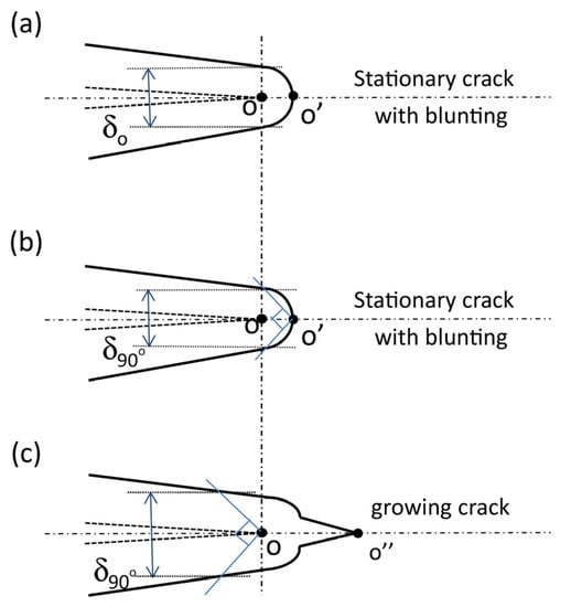
Figure 1.
Three typical CTOD definitions: (a) CTOD defined at the original crack tip, (b) CTOD defined by the 90° intercept approach at the actual, blunted crack tip and (c) CTOD defined by the 90° intercept approach at the original crack tip of a growing crack [4].
For the case of a finite-length surface defect, CTOD will be variable along the crack front. Exact knowledge of CTOD over the entire front is useful for detailed calculations, such as crack profile evolution due to ductile tearing or integrity assessments involving multiple interacting defects. However, clip gauge CTOD calculations merely provide information relating to the center of the defect which is typically the most critical point, but not always.
To experimentally measure the CTOD at locations other than the center of the crack, the authors propose a technique based on full field three-dimensional profile measurement of the notched surface by means of stereoscopic Digital Image Correlation (3D-DIC). The method is based on a plastic hinge model assuming that the crack flanks rotate in a rigid manner around a fixed point (the “plastic hinge”) in the un-cracked ligament. Having measured full-field out-of-plane displacement at the surface of the specimen around the crack using the 3D-DIC method, CTOD can be inferred over the entire crack front. Also, employing DIC is the main motivation for the work carried out in this paper since it reduces the instrumentation effort, allows contactless measurements and is therefore believed to increase the robustness of the measurement. DIC can provide full-field displacement and strain fields at the surface of the specimen, and additional information is obtained compared to traditional measurement techniques such as clip gauges.
2. Experimental Procedure
The experimental investigation of the present work contains measurements of CTOD at various locations within a semi-elliptical surface notch, making use of two techniques: based on DIC and based on replica casting for a specimen. The notch depth was 5 mm and its length at the surface was 28 mm. The specimen was machined from a flat plate of API-5L X70 pipe steel. The initial notch was introduced by fine saw-cutting in two stages. Blade thickness during the first stage was 0.4 mm (notch radius = 0.2 mm) and following the second blade produced a fine initial notch tip radius equal to 0.1.
To measure the full field deformation at the surface of the specimen, the 3D DIC technique has been employed in the present work. Pictures were captured using a stereoscopic system provided by Limess Messtechnic & Software GmbH (Krefeld, Germany) consisting of two synchronized monochromatic 14-bit cameras having a resolution of 2452 by 2054 pixels (5 Megapixels), as shown in Figure 2. Deformation has been derived from the post-processed images using VIC3D software (version 7.2.4). In addition to the stereoscopic camera, an additional third camera was employed to have a wider 2D view allowing to measure strains at sufficiently remote regions from the notch. Figure 1 shows the 3D stereoscopic cameras, 2D camera and the test setup with a mounted specimen. To synchronize the capturing of images, the entire camera system was triggered by the test rig control system with 1 Hz sample frequency.
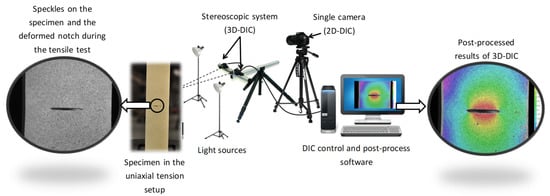
Figure 2.
DIC and test set up.
Having extracted the plate deformations in all three directions, assuming a plastic hinge model and by using basic trigonometry, the CTOD (90° intercept definition δ90, Figure 1c) can be calculated using Equation (1):
where CMOD is the Crack Mouth Opening Displacement, measured as the opening of the notch at the specimen surface (Figure 3). θ is the rotation angle measured at the surface plane by DIC, appearing due to rotation of the crack around the plastic hinge. Finally, a0 is the initial notch depth. Rotation angle (θ) is acquired with a regression analysis of two parameters: pixel distance from the crack line as the independent variable, and the out-of-plane displacement of each pixel as the dependent variable. This analysis is carried out for a set of points located on an imaginary line perpendicular to the semi-ellipse plane at the two sides of the notch. To calculate the crack opening displacement along the crack front, this analysis is reiterated for multiple parallel lines at different distances from the crack center.
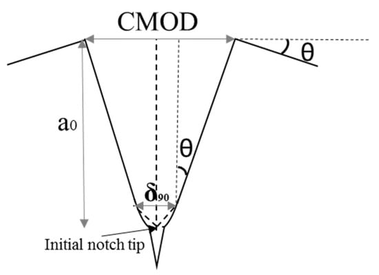
Figure 3.
Schematic view of the notch geometry.
In the present work, to verify the DIC based method, notch replicas were made at different load levels during the test. While the specimen was loaded by the test rig, a silicone rubber mixed with a catalyst was injected into the notch. After hardening the replica, the specimens were loaded further, which allowed to remove the cured replica, and the replica casting procedure was then repeated at a next load level.
3. Results and Discussion
Figure 4 shows measurements of out-of-plane displacement (ΔZ) along lines originating from the notch mouth. It can be observed that very close to the notch tip at the surface (X = 13) there is a marginal out-of-plane displacement and the surface deformation becomes non-linear at closer distances to the notch. In contrast to the tip, in the center of the notch (X = 0 mm), the surface profile close to the notch is almost linear and, as can be expected, the out-of-plane displacement is more prominent in the center. Given that the non-linearity of surface profile adversely affects the regression model accuracy, the regression models are constructed using the data points in a specified zone for which the out-of-plane displacements are close to linear. This zone starts from the notch mouth and ends at a0/2 of the notch, indeed this zone is larger at the notch center where a0 reaches to its maximum, and it is smaller close to the tips where notch depth is very small.
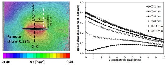
Figure 4.
Out-of-plane measurement along the crack front.
Replica casting was carried out to verify the CTOD measurement by 3D-DIC and Equation (1). Figure 5 illustrates two sample replicas at two stages of the test, before and after the onset of ductile tearing. The replicas were cut at different distances from the notch center, and then the cross sections were investigated to measure CTOD and CMOD (Figure 6). These measurements aim to verify the accuracy of DIC based CTOD measurement along the crack front at multiple points. However, due to the inherent limitation of replica these measurements cannot be applied very close to the tip at the surface (i.e., X > 10 mm) where the silicon has not filled the notch sufficiently. Moreover, replica measurements can only be performed in a limited number of sections, unlike DIC which can be performed for every image set taken, and at every pixel. CTOD has been measured based on 90-degree intercept definition at the initial notch tip in both DIC based and replica based techniques. The initial notch tip can be traced on replicas given that 0.5 mm above it the thickness of the saw cut blades has been changed.
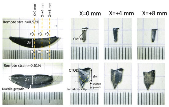
Figure 5.
Replica casting cross sections at various distances from crack center.
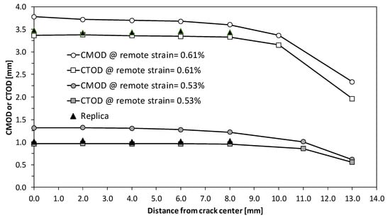
Figure 6.
CMOD and CTOD (δ90) measured by DIC along the crack front at two levels of remote strain compared with CTOD measured using the replica technique.
Note that in the bottom images which show the replica cross sections at the end of the test (remote strain = 0.61%), considerable ductile tearing can be noted all along the crack front. The grown crack has a shape close to a semi-ellipse, quite similar to the original notch, though the crack growth is greater at the deepest point. This conflicts with earlier observations that the semi-elliptical crack growth tends to form a canoe-shape [5].
This comparison proves that DIC based CTOD measurement according to Equation (1) reveals accurate measurement of CTOD not only at the center of the crack like other conventional techniques (i.e., double clip gauge method) but also, uniquely, has the advantage of measuring the CTOD along most of the crack front. This is a prominent advantage when it comes to evaluating the crack driving force in configurations where a non-symmetric opening of the crack is expected, for instance in case of multiple adjacent cracks where interaction affects the opening of the cracks [6,7]. Due to the inherent limitation of DIC in measuring the deformation in the elastic region, the present technique can only be applied with acceptable accuracy when the elastic contribution of CTOD can be neglected (notably, this excludes scenarios of brittle fracture).
4. Conclusions
In the present paper a novel method to measure Crack Tip Opening Displacement (CTOD) using stereoscopic Digital Image Correlation (DIC) is proposed. The proposed technique has been applied to a devoted test involving a surface breaking semi-elliptical notch. To verify the technique, silicon replicas were cast inside the notch in periodic intervals during the test to produce a negative of the crack profile, and were measured afterwards. Results showed that, due to the acceptable agreement between the DIC based measurement and the CTOD measured using the cast replica, the proposed technique has a sufficient accuracy to measure CTOD in plastically deforming specimens. However, due to the limited accuracy of DIC to measure small linear-elastic deformations, the DIC based measurement of CTOD may have a lower accuracy at lower levels of load. The result of this study puts forward a novel, contactless approach to measure CTOD along the entire crack front using full-field deformation when the conventional clip gauge techniques are not capable of providing the required data or are practically undesired.
Author Contributions
K.S. is the main author of this paper. S.H. and W.D.W. supervise this research project.
Acknowledgments
The authors would like to acknowledge the financial support from Ghent University through grant number BOF13/24J/122.
Conflicts of Interest
The authors declare no conflict of interest. The founding sponsors had no role in the design of the study; in the collection, analyses, or interpretation of data; in the writing of the manuscript, and in the decision to publish the results.
References
- Wells, A. Application of fracture mechanics at and beyond general yielding. Br. Weld. J. 1963, 10, 563–570. [Google Scholar]
- Shih, F. Relationships between the J-integral and the crack opening displacement for stationary and extending cracks. J. Mech. Phys. Solids 1981, 29, 305–326. [Google Scholar] [CrossRef]
- Rice, J.R. A path independent integral and the approximate analysis of strain concentration by notches and cracks. J. Appl. Mech. 1968, 35, 379–386. [Google Scholar] [CrossRef]
- Zhu, X.-K.; Zelenak, P.; McGaughy, T. Comparative study of CTOD-resistance curve test methods for SENT specimens. Eng. Fract. Mech. 2017, 172, 17–38. [Google Scholar] [CrossRef]
- Brocks, W.; Künecke, G.; Noack, H.D.; Veith, H. On the transferability of fracture mechanics parameters from specimens to structures using FEM. Nucl. Eng. Des. 1989, 112, 1–14. [Google Scholar] [CrossRef]
- Samadian, K.; Hertelé, S.; De Waele, W. Elastic-plastic defect interaction in (a)symmetrical double edge notched tension specimens. AIMS Mater. Sci. 2017, 4. [Google Scholar] [CrossRef][Green Version]
- Samadian, K.; Hertelé, S.; De Waele, W. A novel flaw alignment approach based on the analysis of bands of maximum strain using full-field deformation measurements. Procedia Struct. Integr. 2017, 5, 1245–1252. [Google Scholar] [CrossRef]
Publisher’s Note: MDPI stays neutral with regard to jurisdictional claims in published maps and institutional affiliations. |
© 2018 by the authors. Licensee MDPI, Basel, Switzerland. This article is an open access article distributed under the terms and conditions of the Creative Commons Attribution (CC BY) license (https://creativecommons.org/licenses/by/4.0/).