2. Methodology and Materials
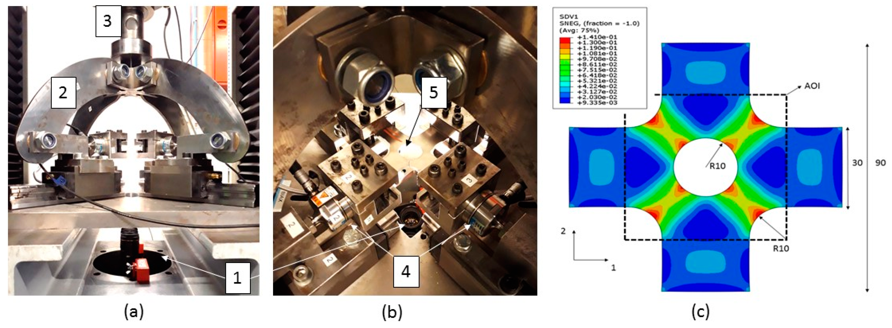
The idea residing in the FEMU-approach relies on a heterogeneously deforming specimen. To this end, a perforated cruciform specimen is used in this paper. The specimen is shown in
Figure 1c. An FE model assuming a von Mises material was used to investigate the stress states generated in the Area Of Interest (AOI), i.e., the region in which the strains are measured. Coppieters et al. [
4] found that this perforated specimen generates stress states covering a large portion of the first quadrant of stress space and concluded that the specimen is a good candidate for inverse yield locus identification through FEMU. The experimental set up is shown in
Figure 1a,b. The biaxial tension apparatus with link mechanism proposed by Nagayasu et al. [
3] is used to subject the perforated specimen to biaxial tension in such a way that an equal velocity of all grips is obtained in the x- and y-directions. The mechanism is mounted in a standard uniaxial tensile machine with a load capacity of 250 kN. Stereo DIC is used to measure the displacement fields at the surface of the deforming specimen. The tensile forces in the arms of the cruciform are measured with load cells with a capacity of 20 kN and synchronized with the DIC system. Abaqus/Standard was used to build the FE model using shell elements (S4R). A low carbon steel with a nominal thickness of 1.2 mm was used in this study. The perforated cruciform specimen was produced by laser cutting. The material was characterized in the first quadrant of stress space using biaxial tensile tests and tube expansion tests (7 linear stress paths). The parameters of the Yld2000-2d yield function were calibrated using
,
,
,
,
,
,
and
, where
and
are the
-value and tensile flow stress measured at an angle of # from the RD, respectively, and
and
are the plastic strain rate ratio
and the flow stress at equibiaxial tension
1:1, respectively. The exponent
M of the Yld2000-2d yield function was calibrated by minimizing the root mean square error between the selected contour of plastic work and the calculated yield locus. Differential work hardening was captured by changing the parameters and the exponent of the Yld2000-2d yield criterion as a function of the reference plastic strain
.
Figure 2 shows the evolution of the Yld2000-2d yield function as a function of different values of plastic reference strain
. The Rolling Direction (RD) and the Transverse Direction (TD) of the material are defined as the as the
x- and
y-axis, respectively. The strain hardening behavior in the RD was identified using a quasi-static standard tensile test.
The basic principle of FEMU is to minimise the discrepancy between the experimentally measured and numerically computed response by adapting the unknown parameters of the anisotropic yield criterion in the FE model. In this work, the Levenberg-Marquardt minimisation algorithm is used to minimize the following cost function:
With
p the vector of unknown parameters of the anisotropic yield function,
m the number of load steps (
m = 1 in this paper) and
ni the number of data points in the DIC measurement at load step
i. The subscripts
exp and
num indicate experimental response and numerical response, receptively.
Figure 3a shows the experimentally obtained strain field at
in the transverse direction (TD). The maximum equivalent plastic strain at this load step was about 0.2 and the average strain rate was kept below
3. Results and Discussion
The experimental data at
in TD), is used to identify the plane stress Hill48 yield criterion using FEMU. The most straightforward approach is to use the measured forces in the arms of the cruciform as boundary conditions in the FE model of the perforated cruciform specimen. Coppieters et al. [
5] found that this approach is liable to modelling errors in the load distribution. The latter study showed that applying displacement boundary conditions leads to more reliable results. As opposed to a force distribution, displacement components can be measured locally using DIC and directly implemented as boundary conditions in the FE model.
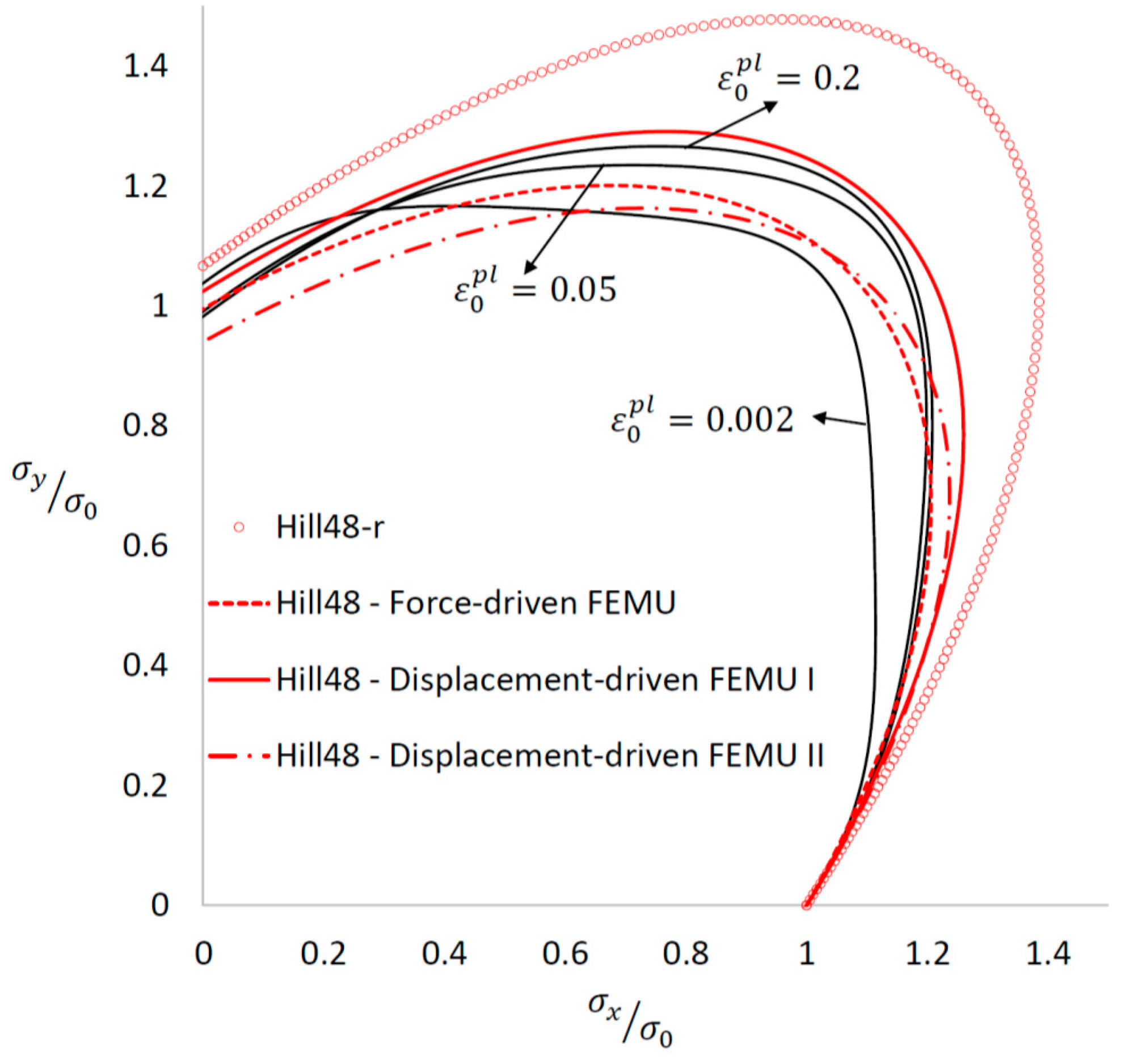
Figure 2 shows the effect of boundary conditions on the identification of the Hill48 yield criterion. The yield locus labeled
Hill48–Force-driven FEMU was identified by assuming a distributed shell edge load in the FE model. The yield locus
Hill48–Displacement-driven FEMU I was identified by adopting locally measured displacement components as boundary conditions. Both yield loci were identified by solely minimizing the discrepancy between experimental and numerical strain values. It can be inferred from
Figure 3 that FEMU is highly sensitive to an erroneous modelling of the boundary conditions.
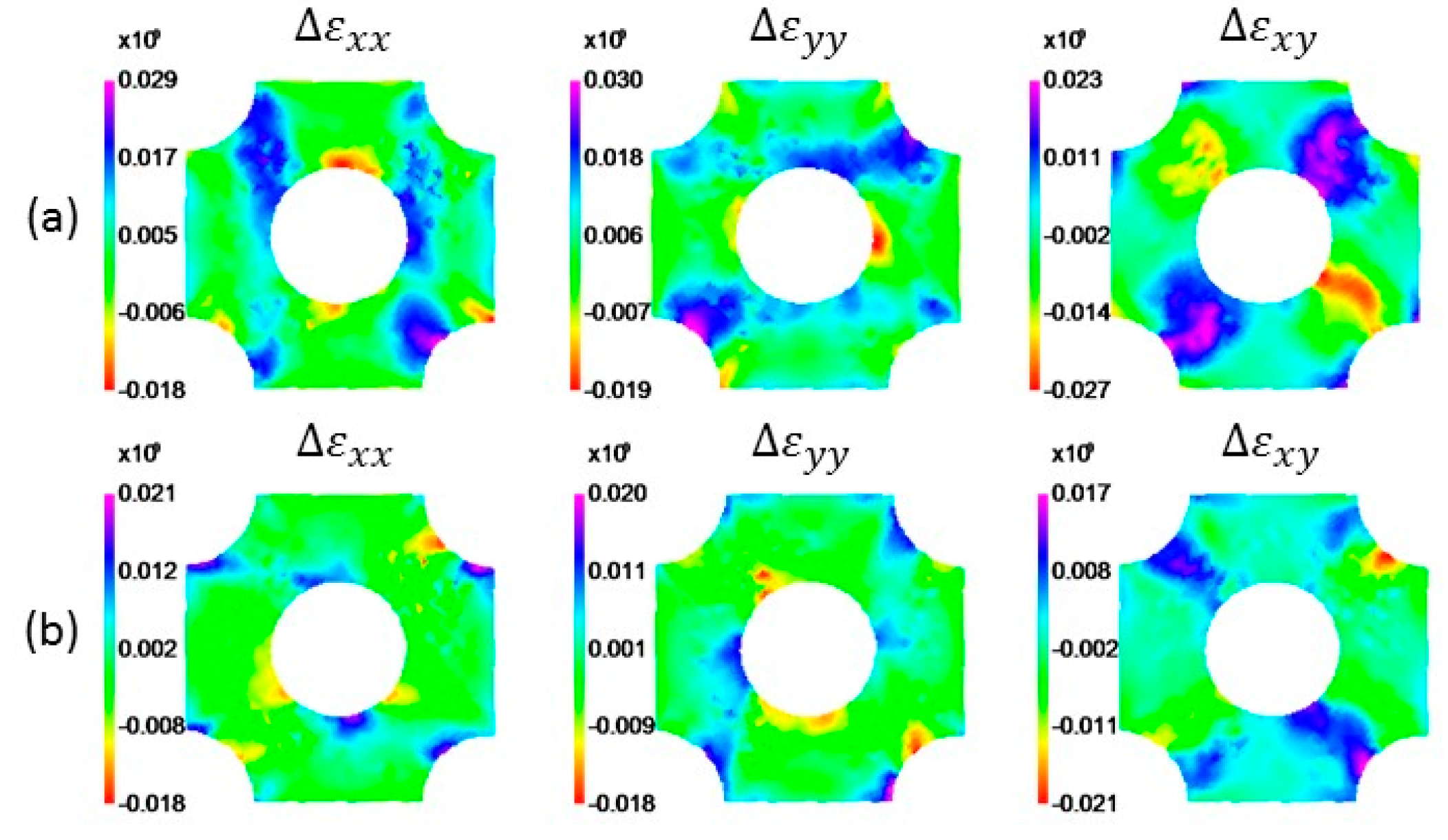
Figure 3b,c show the absolute error in the strain fields obtained with both identified yield loci.
Figure 2.
Normalized yield loci: Reference yield loci (Yld2000-2d) and inversely identified yield loci (Hill48).
Figure 2.
Normalized yield loci: Reference yield loci (Yld2000-2d) and inversely identified yield loci (Hill48).
The strain error map obtained with yield locus
Hill48–Force-driven FEMU (
Figure 3b) clearly shows that the strain error in the transition region towards the arms is larger than the results obtained with the yield locus
Hill48–Displacement-driven FEMU I. Nevertheless, the difference in predicted strain values by both identified yield loci is deemed small. The relative error with respect to the predicted tensile force in the TD by
Hill48–Displacement-driven FEMU I, however, is about 14%, see
Table 1. The yield locus
Hill48–Displacement-driven FEMU II shown in
Figure 2 is identified by including the force (TD) in the cost function. It can be inferred that including the force significantly affects the yield locus identification. The relative error in the force prediction is in this case below 1% (see
Table 1) while the strain error map (
Figure 3d) is similar to the one obtained using the yield locus
Hill48–Displacement-driven FEMU I (
Figure 3c). As a consequence, it can be concluded that
Hill48–Displacement-driven FEMU II yields the most accurate identification. In the remainder of this work, we refer to this yield locus as the inversely identified Hill48 yield function.
Comparison with the bench mark characterization through homogeneous biaxial tensile testing (see solid black loci in
Figure 2), however, reveals a significant difference. The main reason for this is that the identified Hill48 yield criterion cannot describe the actual material behavior. Indeed, the material exhibits differential work hardening which cannot be captured by the adopted Hill48 yield function. In essence, the FEMU fits the Hill48 yield function to the available experimental data, and, consequently, merely yields an average of the actual yield behavior. Given the fact that the material exhibits differential work hardening also affects the influence of the number of load steps used in the FEMU. Here, only the final state was taken into account which means that the deformation history is ignored. Finally, it must be noted that the heterogeneous experiment generates stress states which are not present in the homogeneous biaxial tensile tests. Indeed, the experiment on a perforated specimen generates shear stresses which are absent during conventional biaxial tensile testing in the first quadrant of stress space. The predictive accuracy of the inversely identified Hill48 yield function can be compared with the accuracy of conventionally calibrated anisotropic yield functions.
Figure 2 shows the Hill48 yield function (labeled
Hill48-r) calibrated using the
r-values (
. The black yield loci represent the actual material behavior modelled by the Yld2000-2d (DH) yield function dependable of the reference plastic strain to reproduce the experimentally observed differential work hardening of the test material during biaxial tensile testing using cruciform specimens. Both the Hill48-r and the Yld2000-2d yield functions are used to reproduce the experiment using a displacement-driven finite element simulation. The strain error maps are shown in
Figure 4 and it can be inferred that the Yld2000-2d yield function predicts the strain field more accurately than the Hill48-r yield function. In addition, the force prediction using Yld2000-2d (DH) is much more accurate (relative error 6.8% versus 25.7%, see
Table 1) than by using Hill48-r. The inversely identified Hill48 yield function, however, predicts a similar strain error map (
Figure 3d) as the one obtained with the Yld2000-2d (DH) yield function (
Figure 4b). Additionally, the force prediction of the inversely identified Hill48 yield function is in better agreement with the experiment (see
Table 1). This is, however, not surprising since the Hill48 yield function was inversely identified using the same experiment. Given that the Yld2000-2d (DH) yield function was calibrated by other experiments, assessment using the perforated cruciform is valid and it can be concluded that the material modelling approach using Yld2000-2d (DH) yields accurate results. In order to assess the accuracy of both the yield functions, a tensile test in the 45-degree direction (45D) to RD can be used as this experiment was not used for calibration purposes.
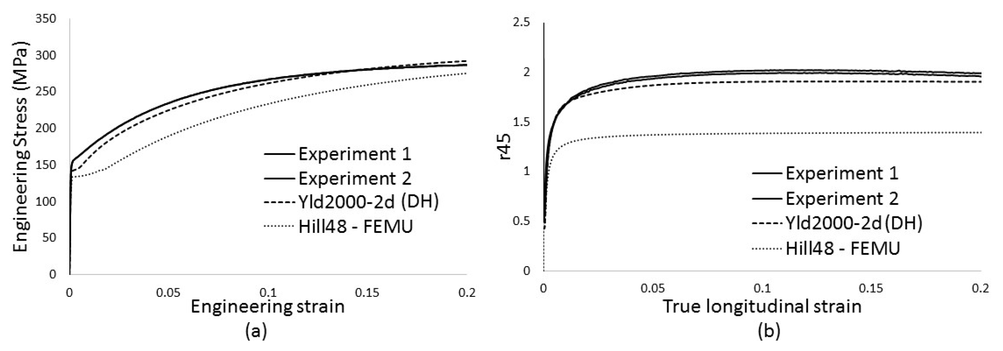
Figure 5 shows the experimental data along with the FE simulations of a standard tensile test in the 45D.
Figure 5a shows the measurement and the prediction of the engineering stress-strain curve using both yield functions. It can be inferred that the Yld2000-2d (DH) yield function enables to reproduce the stress-strain curve much more accurately than the inversely identified Hill48 yield criterion.
Figure 5b shows the evolution of
as a function of the true strain in the tensile direction (45D). The experimental data was obtained through DIC measurements. Unlike the inversely identified Hill48 yield function, the Yld2000-2d (DH) yield function accurately reproduces the
-evolution. From this it can be concluded that the validity of the inversely identified Hill48 yield function is strictly confined to experiment used in the FEMU approach, i.e., the perforated cruciform specimen under biaxial tension.
Figure 3.
(a) Experimental strain field at approximately 8kN (TD); Discrepancy between experimental and numerical strain components obtained with the identified Hill48 yield criterion; (b) Force-driven FEMU (strain-based cost function); (c) Displacement-driven FEMU (strain-based cost function); (d) Displacement-driven FEMU (strain –and force-based cost function).
Figure 4.
Discrepancy between experimental and numerical strain components at load step 8 kN (TD): (a) Hill48-r yield criterion; (b) Yld2000-2d (DH) yield criterion that reproduces the differential hardening of the test material.
Figure 4.
Discrepancy between experimental and numerical strain components at load step 8 kN (TD): (a) Hill48-r yield criterion; (b) Yld2000-2d (DH) yield criterion that reproduces the differential hardening of the test material.
Figure 5.
Assessment of the identified yield functions through a tensile test in the 45D (a) Engineering stress–engineering strain curve; (b) evolution as a function of the true longitudinal strain.
Figure 5.
Assessment of the identified yield functions through a tensile test in the 45D (a) Engineering stress–engineering strain curve; (b) evolution as a function of the true longitudinal strain.

 ,
, 

